CN211523894U - A solar decorative panel applied to the facade of a building - Google Patents
A solar decorative panel applied to the facade of a building Download PDFInfo
- Publication number
- CN211523894U CN211523894U CN201922223183.4U CN201922223183U CN211523894U CN 211523894 U CN211523894 U CN 211523894U CN 201922223183 U CN201922223183 U CN 201922223183U CN 211523894 U CN211523894 U CN 211523894U
- Authority
- CN
- China
- Prior art keywords
- photovoltaic cell
- layer
- decorative panel
- solar
- facade
- Prior art date
- Legal status (The legal status is an assumption and is not a legal conclusion. Google has not performed a legal analysis and makes no representation as to the accuracy of the status listed.)
- Expired - Fee Related
Links
Images


Classifications
-
- Y—GENERAL TAGGING OF NEW TECHNOLOGICAL DEVELOPMENTS; GENERAL TAGGING OF CROSS-SECTIONAL TECHNOLOGIES SPANNING OVER SEVERAL SECTIONS OF THE IPC; TECHNICAL SUBJECTS COVERED BY FORMER USPC CROSS-REFERENCE ART COLLECTIONS [XRACs] AND DIGESTS
- Y02—TECHNOLOGIES OR APPLICATIONS FOR MITIGATION OR ADAPTATION AGAINST CLIMATE CHANGE
- Y02B—CLIMATE CHANGE MITIGATION TECHNOLOGIES RELATED TO BUILDINGS, e.g. HOUSING, HOUSE APPLIANCES OR RELATED END-USER APPLICATIONS
- Y02B10/00—Integration of renewable energy sources in buildings
- Y02B10/10—Photovoltaic [PV]
-
- Y—GENERAL TAGGING OF NEW TECHNOLOGICAL DEVELOPMENTS; GENERAL TAGGING OF CROSS-SECTIONAL TECHNOLOGIES SPANNING OVER SEVERAL SECTIONS OF THE IPC; TECHNICAL SUBJECTS COVERED BY FORMER USPC CROSS-REFERENCE ART COLLECTIONS [XRACs] AND DIGESTS
- Y02—TECHNOLOGIES OR APPLICATIONS FOR MITIGATION OR ADAPTATION AGAINST CLIMATE CHANGE
- Y02E—REDUCTION OF GREENHOUSE GAS [GHG] EMISSIONS, RELATED TO ENERGY GENERATION, TRANSMISSION OR DISTRIBUTION
- Y02E10/00—Energy generation through renewable energy sources
- Y02E10/50—Photovoltaic [PV] energy
Landscapes
- Photovoltaic Devices (AREA)
- Finishing Walls (AREA)
Abstract
本实用新型属于太阳能光伏电池领域,并公开了一种应用于建筑外立面的太阳能装饰板。该装饰板包括外立面和内侧面,其中,对于装饰板的外立面,其自下而上包括基板、纹理层、光伏电池层和封装薄膜,光伏电池层用于吸收太阳光并利用吸收的太阳光发电,纹理层图案根据建筑外立面所需进行设定,封装薄设置在光伏电用于保护光伏电池层;对于装饰板的内侧面表面设置有母扣,该母扣与相邻的装饰板内侧面上的子扣配合形成卡扣结构,该卡扣结构一方面实现相邻的装饰板结构上的连接,另一方面保证相邻的装饰板中光伏电池层的串联。通过本实用新型,实现将光伏电池应用与建筑外立面,解决太阳能板安装中电路和装饰板的安装问题。
The utility model belongs to the field of solar photovoltaic cells, and discloses a solar decorative panel applied to the exterior facade of a building. The decorative panel includes an outer facade and an inner side, wherein, for the outer facade of the decorative panel, it includes a substrate, a texture layer, a photovoltaic cell layer and an encapsulation film from bottom to top, and the photovoltaic cell layer is used for absorbing sunlight and utilizing absorption For solar power generation, the texture layer pattern is set according to the needs of the building facade, and the encapsulation film is arranged on the photovoltaic power layer to protect the photovoltaic cell layer; the inner side surface of the decorative board is provided with a female button, which is adjacent to the The sub-buckles on the inner side of the decorative board are matched to form a buckle structure, which on the one hand realizes the structural connection of the adjacent decorative boards, and on the other hand ensures the series connection of the photovoltaic cell layers in the adjacent decorative boards. The utility model realizes the application of photovoltaic cells to the building facade, and solves the installation problem of circuits and decorative panels in the installation of solar panels.
Description
技术领域technical field
本实用新型属于太阳能光伏电池领域,更具体地,涉及一种应用于建筑外立面的太阳能装饰板。The utility model belongs to the field of solar photovoltaic cells, and more particularly relates to a solar decorative panel applied to the facade of a building.
背景技术Background technique
随着能源需求的增大,太阳能光伏系统仅应用于建筑屋顶已远不能满足需求,除建筑屋顶,建筑立面面积一般较屋顶更大,因而具有不小的太阳能利用潜力;现有光伏电池材料主要包括单晶硅,多晶硅,CIS、CdTe、CIGS等材料,其中CIGS材料相较于其他光伏材料,其具有光电转化效率高,稳定性好、厚度低,光透性较好,并可以制做成可弯曲的薄膜光伏电池。With the increase of energy demand, the solar photovoltaic system can not meet the demand only if it is only applied to the building roof. Except for the building roof, the building façade area is generally larger than that of the roof, so it has a lot of potential for solar energy utilization; existing photovoltaic cell materials It mainly includes monocrystalline silicon, polycrystalline silicon, CIS, CdTe, CIGS and other materials. Compared with other photovoltaic materials, CIGS materials have high photoelectric conversion efficiency, good stability, low thickness and good light transmittance, and can be made into into flexible thin-film photovoltaic cells.
光伏电池在建筑上多应用与建筑屋面,通过在屋面安装支架固定光伏电池组件,或将光伏材料与屋面瓦结合形成一体式产品来进行安装;光伏电池应用于建筑立面的方式包括:结合立面遮阳设置、立面安装支架设置、与墙体结合一体化设置等,其中,结合立面遮阳或通过支架安装太阳能安装光伏电池的方式,其安装面积较小,对立面造型影响大。而与建筑墙体一体化设置需要将建筑墙体与光伏电池和附属设备预制在一起,其生产、安装相对复杂,且难以更换与维修;同时,应用于建筑立面的光伏电池由于其色彩单一,难以满足建筑立面的多样化需求。Photovoltaic cells are widely used in buildings and building roofs. They are installed by fixing photovoltaic cell components on roof mounting brackets, or combining photovoltaic materials with roof tiles to form an integrated product; photovoltaic cells are applied to building facades. The installation of surface shading, the installation of vertical installation brackets, and the integration with the wall, etc., among which, the combination of the facade shading or the solar installation of photovoltaic cells through brackets has a small installation area and has a great impact on the facade shape. The integration with the building wall requires the building wall, photovoltaic cells and auxiliary equipment to be prefabricated together, which is relatively complicated in production and installation, and difficult to replace and maintain. , it is difficult to meet the diverse needs of building facades.
实用新型内容Utility model content
针对现有技术的以上缺陷或改进需求,本实用新型提供了一种应用于建筑外立面的太阳能装饰板,其通过对太阳能装饰板的整体布局和关键部件的结构设计,对其外立面采用光伏电池层,使得外立面能充分利用太阳能发电,同时保留外立面的装饰作用,另外,还对相邻装饰板的背面的连接结构进行设计,使得相邻的装饰板不仅实现结构上的连接,也实现发电光伏电池层的串联,保证电路上的串联。In view of the above defects or improvement needs of the prior art, the present utility model provides a solar decorative panel applied to the facade of a building. The photovoltaic cell layer is adopted, so that the façade can make full use of solar power generation, while retaining the decorative effect of the façade. In addition, the connection structure of the backside of the adjacent decorative panels is also designed, so that the adjacent decorative panels not only realize structural The connection also realizes the series connection of the power generation photovoltaic cell layers to ensure the series connection on the circuit.
为实现上述目的,按照本实用新型,提供了一种应用于建筑外立面的太阳能装饰板,其特征在于,该装饰板包括外立面和内侧面,其中,In order to achieve the above purpose, according to the present utility model, a solar decorative panel applied to the facade of a building is provided, wherein the decorative panel includes an outer facade and an inner side, wherein,
对于所述装饰板的外立面,其自下而上包括基板、纹理层、光伏电池层和封装薄膜,所述基板是所述纹理层、光伏电池层和封装薄膜的载体,所述光伏电池层成透明状,用于吸收太阳光并利用吸收的太阳光发电,所述纹理层设置在所述光伏电池层的下方,该纹理层表面设置有根据建筑外立面所需进行设定的图案,当太阳光穿过所述光伏电池层照射在所述纹理层上时,所述光伏电池层的本色与所述纹理层的颜色混合,实现所述装饰板颜色的调色,所述封装薄设置在所述光伏电池层的上方,用于保护所述光伏电池层;For the facade of the decorative board, it includes a substrate, a texture layer, a photovoltaic cell layer and an encapsulation film from bottom to top, and the substrate is a carrier of the texture layer, the photovoltaic cell layer and the encapsulation film, and the photovoltaic cell The layer is transparent to absorb sunlight and use the absorbed sunlight to generate electricity, the texture layer is arranged under the photovoltaic cell layer, and the surface of the texture layer is provided with a pattern set according to the needs of the building facade , when sunlight passes through the photovoltaic cell layer and irradiates on the texture layer, the natural color of the photovoltaic cell layer is mixed with the color of the texture layer to realize the color tone of the decorative board, and the encapsulation thin disposed above the photovoltaic cell layer, for protecting the photovoltaic cell layer;
对于所述装饰板的内侧面,其表面设置有母扣,该母扣与相邻的装饰板内侧面上的子扣配合形成卡扣结构,该卡扣结构一方面实现相邻的所述装饰板结构上的连接,另一方面保证相邻的所述装饰板中光伏电池层的串联。The inner side of the decorative board is provided with a female buckle, and the female buckle cooperates with the sub-buckles on the inner side of the adjacent decorative board to form a buckle structure. On the one hand, the buckle structure realizes the adjacent decoration. The connection on the board structure, on the other hand, ensures the series connection of the photovoltaic cell layers in the adjacent decorative boards.
进一步优选地,所述光伏电池层包括背电极、电池层和正电极,其中,所述电池层用于发电,所述正电极和背电极分别为所述电池层的正极和负极。Further preferably, the photovoltaic cell layer includes a back electrode, a cell layer and a positive electrode, wherein the cell layer is used to generate electricity, and the positive electrode and the back electrode are the positive electrode and the negative electrode of the cell layer, respectively.
进一步优选地,所述母扣设置在所述基板的背面,呈凸台状,该凸台上设置有凹槽,所述子扣的表面设置有凸起,该凸起与所述凹槽配合实现所述母扣与子扣的配合;Further preferably, the female buckle is arranged on the back of the base plate, in the shape of a boss, the boss is provided with a groove, the surface of the sub buckle is provided with a protrusion, and the protrusion is matched with the groove. realize the cooperation of the female buckle and the child buckle;
另外,所述凸起和凹槽中均金属片,所述凸起上的金属片一端与该凸起所在装饰板外立面中的背电极/正电极相连,所述凹槽中的金属片一端与该凹槽所在装饰板外立面中的正电极/背电极相连,当所述母扣和子扣配合安装时,相邻的装饰板中光伏电池层串联。In addition, the protrusions and the grooves are both metal sheets, and one end of the metal sheet on the protrusion is connected to the back electrode/positive electrode on the outer façade of the decorative board where the protrusion is located, and the metal sheet in the groove is One end is connected to the positive electrode/back electrode in the outer façade of the decorative board where the groove is located. When the female button and the sub-button are installed together, the photovoltaic cell layers in the adjacent decorative boards are connected in series.
进一步优选地,所述凸起中背后还设置有弹簧,当发生震动时,所述弹簧用于缓冲,以此保证所述凹槽中的金属片与所述凸起上的金属片接触良好。Further preferably, a spring is also arranged in the back of the protrusion, and when a vibration occurs, the spring is used for buffering, so as to ensure that the metal sheet in the groove and the metal sheet on the protrusion are in good contact.
进一步优选地,所述光伏电池层采用CIGS光伏电池。Further preferably, the photovoltaic cell layer adopts a CIGS photovoltaic cell.
进一步优选地,所述封装薄膜的材料EVA胶膜,厚度为0.3~0.8mm。Further preferably, the material of the encapsulation film is an EVA film with a thickness of 0.3-0.8 mm.
进一步优选地,所述纹理层的材料为PET薄膜,厚度为0.025~0.05mm。Further preferably, the texture layer is made of PET film with a thickness of 0.025-0.05 mm.
总体而言,通过本实用新型所构思的以上技术方案与现有技术相比,能够取得下列有益效果:In general, compared with the prior art, the following beneficial effects can be achieved through the above technical solutions conceived by the present utility model:
1、本实用新型通过将光伏电池层设置在建筑的外立面,与传统的设置在建筑物顶面的太阳能电池相比,其一方面增大了太阳能的吸收面,更加充分利用太阳能,同时,该透明光伏电池层后设置的纹理层也保证了建筑外立面的外观需求;1. By arranging the photovoltaic cell layer on the outer facade of the building, compared with the traditional solar cell arranged on the top surface of the building, the utility model increases the absorption surface of the solar energy on the one hand, makes more full use of the solar energy, and at the same time. , the texture layer arranged behind the transparent photovoltaic cell layer also ensures the appearance requirements of the building facade;
2、本实用新型中在相邻的太阳能装饰板的背面设置有卡扣,在安装太阳能装饰板时,同时实现了装饰板结构上的连接和电路的连接,与传统的装饰板相比,避免将机械结构连接和电路连接分开安装,降低由不同的安装工人分别对不同部分安装带来的人工成本;2. In the utility model, a buckle is arranged on the back of the adjacent solar decorative panels. When installing the solar decorative panels, the connection on the structure of the decorative panels and the connection of the circuit are realized at the same time. Compared with the traditional decorative panels, it avoids the The mechanical structure connection and the circuit connection are installed separately to reduce the labor cost caused by the installation of different parts by different installers;
3、本实用新型中通过采用CIGS光伏电池,一方面该光伏电池的透光性好,能完全呈现纹理层的图案,另一方面该光伏电池采光好,太阳能利用率高,且其相比于传统的仅能应用于建筑物顶面的单晶硅、多晶硅太阳能板的太阳能板而言,重量轻,不需额外的支撑结构,适用于建筑物外立面。3. By adopting the CIGS photovoltaic cell in the utility model, on the one hand, the photovoltaic cell has good light transmittance and can fully present the pattern of the textured layer; Traditional solar panels, which can only be applied to monocrystalline silicon and polycrystalline silicon solar panels on the top of buildings, are light in weight and do not require additional support structures, making them suitable for building facades.
附图说明Description of drawings
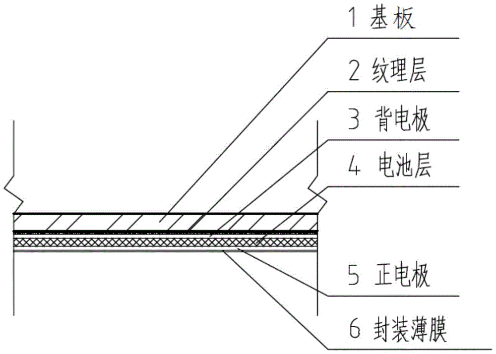
图1是按照本实用新型的优选实施例所构建的太阳能装饰板外立面的截面示意图;1 is a schematic cross-sectional view of the exterior facade of a solar decorative panel constructed according to a preferred embodiment of the present invention;
图2是按照本实用新型的优选实施例所构建的太阳能装饰板内侧面的截面示意图;FIG. 2 is a schematic cross-sectional view of the inner side of the solar decorative panel constructed according to the preferred embodiment of the present invention;
图3是按照本实用新型的优选实施例所构建的太阳能装饰板卡扣的放大图;3 is an enlarged view of a solar decorative panel buckle constructed according to a preferred embodiment of the present invention;
图4是按照本实用新型的优选实施例所构建的太阳能装饰板安装在建筑外立面后形成的太阳能光伏系统的示意图。4 is a schematic diagram of a solar photovoltaic system formed after the solar decorative panel constructed according to the preferred embodiment of the present invention is installed on the exterior facade of the building.
在所有附图中,相同的附图标记用来表示相同的元件或结构,其中:Throughout the drawings, the same reference numbers are used to refer to the same elements or structures, wherein:
1-基板,2-纹理层,3-背电极,4-电池层,5-正电极,6-封装薄膜,7-胶膜,8-金属片,9-弹簧,10-龙骨,11-导电滑块,12-母扣,13-子扣,14-凸起,15-凹槽,16-逆变器。1-substrate, 2-texture layer, 3-back electrode, 4-battery layer, 5-positive electrode, 6-encapsulation film, 7-adhesive film, 8-metal sheet, 9-spring, 10-keel, 11-conductive Slider, 12-female buckle, 13-child buckle, 14-protrusion, 15-groove, 16-inverter.
具体实施方式Detailed ways
为了使本实用新型的目的、技术方案及优点更加清楚明白,以下结合附图及实施例,对本实用新型进行进一步详细说明。应当理解,此处所描述的具体实施例仅仅用以解释本实用新型,并不用于限定本实用新型。此外,下面所描述的本实用新型各个实施方式中所涉及到的技术特征只要彼此之间未构成冲突就可以相互组合。In order to make the purpose, technical solutions and advantages of the present utility model more clearly understood, the present utility model will be further described in detail below with reference to the accompanying drawings and embodiments. It should be understood that the specific embodiments described herein are only used to explain the present invention, and are not intended to limit the present invention. In addition, the technical features involved in the various embodiments of the present invention described below can be combined with each other as long as there is no conflict with each other.
一种应用于建筑外立面的太阳能装饰板,该装饰板包括外立面和内侧面,其中,A solar decorative panel applied to the facade of a building, the decorative panel includes an outer facade and an inner side, wherein,
如图1所示,对于所述装饰板的外立面,其自下而上包括基板1、纹理层2、光伏电池层和封装薄膜6,所述基板1是所述纹理层2、光伏电池层和封装薄膜6的载体,所述光伏电池层成透明状,用于吸收太阳光并利用吸收的太阳光发电,所述纹理层2设置在所述光伏电池层的下方,该纹理层2表面设置有根据建筑外立面所需进行设定的图案,当太阳光穿过所述光伏电池层照射在所述纹理层上时,所述光伏电池层的本色与所述纹理层的颜色混合,实现所述装饰板颜色的调色,所述封装薄6设置在所述光伏电池层的上方,用于保护所述光伏电池层;As shown in FIG. 1 , the outer facade of the decorative board includes a substrate 1, a texture layer 2, a photovoltaic cell layer and an
如图2和3所示,对于所述装饰板的内侧面,其表面设置有母扣12,该母扣与相邻的装饰板内侧面上的子扣13配合形成卡扣结构,该卡扣结构一方面实现相邻的所述装饰板结构上的连接,另一方面保证相邻的所述装饰板中光伏电池层的串联。As shown in Figures 2 and 3, the inner side of the decorative panel is provided with a
优选地,所述光伏电池层包括背电极3、电池层4和正电极5,其中,所述电池层4用于发电,所述正电极5和背电极3分别为所述电池层的正极和负极。Preferably, the photovoltaic cell layer includes a
优选地,所述母扣12设置在所述基板的背面,呈凸台状,该凸台结构上设置有凹槽15,所述子扣13的表面设置有凸起14,该凸起14与所述凹槽15配合实现所述母扣与子扣的配合;Preferably, the
另外,所述凸起14和凹槽15中均金属片8,所述凸起14上的金属片一端与该凸起所在装饰板外立面中的背电极/正电极相连,所述凹槽15中的金属片一端与该凹槽所在装饰板外立面中的正电极/背电极相连,当所述母扣和子扣配合安装时,相邻的装饰板中光伏电池层串联。In addition, the
优选地,所述凸起14中背后还设置有弹簧9,当发生震动时,所述弹簧用于缓冲,以此保证所述凹槽中的金属片与所述凸起上的金属片接触良好。Preferably, a spring 9 is also arranged on the back of the
优选地,所述光伏电池层采用CIGS光伏电池。Preferably, the photovoltaic cell layer adopts a CIGS photovoltaic cell.
优选地,所述封装薄膜6的材料为EVA胶膜,该材料为光伏领域常见的组件表面封装材料,其在粘着、耐久、光学特性等方面具有较好的性能。目前在光伏电池组件上常用的EVA胶膜厚度为0.3~0.8mm。Preferably, the material of the
优选地,所述材料纹理层的材料为PET薄膜,该材料为光伏电池常用的背板封装材料,同时该材料具有良好的染色性能,适于制作多种纹理,目前在光伏电池组件上常用的PET薄膜厚度为0.025~0.05mm。Preferably, the material of the material texture layer is a PET film, which is a commonly used backsheet packaging material for photovoltaic cells, and has good dyeing properties, suitable for making a variety of textures, and is currently commonly used in photovoltaic cell components. The thickness of the PET film is 0.025-0.05mm.
在本实用新型的实施例中,可将传统建筑立面装饰材料中的金属、陶瓷、玻璃作为太阳能装饰板的基板,本实用新型提供的太阳能装饰板可以直接用作建筑外立面的装饰板材,在基板光伏电池层之间加入纹理层,利用CIGS光伏电池材料的高透光性将内层材质纹理进行展现,并利用电池层的本色与纹理层的颜色混合来进行调色,从而通过更换材质层来形成多种不同颜色纹理的光伏装饰板材,以解决见建筑对立面色彩纹理多样化需要的问题。In the embodiment of the present invention, metal, ceramics and glass in traditional building facade decorative materials can be used as the substrate of the solar decorative panel, and the solar decorative panel provided by the present invention can be directly used as the decorative plate for the building facade , adding a texture layer between the photovoltaic cell layers of the substrate, using the high light transmittance of the CIGS photovoltaic cell material to display the texture of the inner layer material, and using the natural color of the battery layer and the color of the texture layer to mix to color, so that by replacing The material layer is used to form photovoltaic decorative panels of various colors and textures, so as to solve the problem of the diversification of color and texture on the opposite side of the building.
对于相邻的太阳能装饰板的连接问题,采用在装饰板的背面设置具备导电功能的卡扣的结构。For the connection of adjacent solar decorative panels, a structure in which a buckle with a conductive function is provided on the back of the decorative panel is adopted.
如图4所示,本实用新型的太阳能装饰板在建筑立面的安装时,仅需采用常规装饰板材的安装方式,即利用龙骨10干挂,本实用新型的太阳能安装在建筑物外立面时,可与逆变器16连接形成太阳能光伏系统,太阳能装饰板与龙骨上的导电滑11块连接,龙骨采用导电龙骨,由于逆变器16无法安装在建筑外墙上,采用导电龙骨将太阳能装饰板与逆变器连接,以此实现太阳能光伏系统电路的闭合。As shown in FIG. 4 , when the solar decorative panel of the present invention is installed on the building facade, it only needs to adopt the installation method of conventional decorative plates, that is, dry hanging by using the
本领域的技术人员容易理解,以上所述仅为本实用新型的较佳实施例而已,并不用以限制本实用新型,凡在本实用新型的精神和原则之内所作的任何修改、等同替换和改进等,均应包含在本实用新型的保护范围之内。Those skilled in the art can easily understand that the above are only preferred embodiments of the present invention, and are not intended to limit the present invention. Any modifications, equivalent replacements and replacements made within the spirit and principles of the present invention Improvements, etc., should be included within the protection scope of the present invention.
Claims (7)
Priority Applications (1)
| Application Number | Priority Date | Filing Date | Title |
|---|---|---|---|
| CN201922223183.4U CN211523894U (en) | 2019-12-12 | 2019-12-12 | A solar decorative panel applied to the facade of a building |
Applications Claiming Priority (1)
| Application Number | Priority Date | Filing Date | Title |
|---|---|---|---|
| CN201922223183.4U CN211523894U (en) | 2019-12-12 | 2019-12-12 | A solar decorative panel applied to the facade of a building |
Publications (1)
| Publication Number | Publication Date |
|---|---|
| CN211523894U true CN211523894U (en) | 2020-09-18 |
Family
ID=72445483
Family Applications (1)
| Application Number | Title | Priority Date | Filing Date |
|---|---|---|---|
| CN201922223183.4U Expired - Fee Related CN211523894U (en) | 2019-12-12 | 2019-12-12 | A solar decorative panel applied to the facade of a building |
Country Status (1)
| Country | Link |
|---|---|
| CN (1) | CN211523894U (en) |
Cited By (1)
| Publication number | Priority date | Publication date | Assignee | Title |
|---|---|---|---|---|
| CN110939244A (en) * | 2019-12-12 | 2020-03-31 | 华中科技大学 | Solar decorative plate applied to building facade |
-
2019
- 2019-12-12 CN CN201922223183.4U patent/CN211523894U/en not_active Expired - Fee Related
Cited By (1)
| Publication number | Priority date | Publication date | Assignee | Title |
|---|---|---|---|---|
| CN110939244A (en) * | 2019-12-12 | 2020-03-31 | 华中科技大学 | Solar decorative plate applied to building facade |
Similar Documents
| Publication | Publication Date | Title |
|---|---|---|
| CN104409536B (en) | Integrative color photovoltaic assembly for building interior decoration and preparation method thereof | |
| AU2018101583A4 (en) | Solar cell module | |
| CN208111462U (en) | A kind of solar panel | |
| CN202227625U (en) | Integrated thin-film solar building board | |
| CN202205777U (en) | Building-material-type double-faced glass photovoltaic component | |
| WO2023077346A1 (en) | Solar module and method for producing the same | |
| CN201570502U (en) | Colorful solar photovoltaic component | |
| CN205070925U (en) | Photovoltaic module and photovoltaic curtain wall with heat preservation function | |
| CN201546388U (en) | A kind of architectural glass that can use solar energy to generate electricity | |
| CN101262020A (en) | A solar cell module based on building tiles | |
| CN206022391U (en) | A kind of printing opacity cadmium telluride photovoltaic building element | |
| CN219329264U (en) | BIPV double-sided color photovoltaic module | |
| CN106685323B (en) | The double glass structure generating electricity on two sides photovoltaic tiles of lightweight | |
| CN102561569B (en) | Solar photovoltaic power generation light-permeable glass curtain wall component | |
| CN202120950U (en) | Frameless BIVP solar energy battery pack | |
| CN105870231B (en) | The double glass photovoltaic curtain wall light-transmitting components of novel crystal silicon | |
| CN110939244A (en) | Solar decorative plate applied to building facade | |
| CN107963843A (en) | A kind of solar energy porcelain tendre ornament materials and preparation method thereof | |
| CN203277462U (en) | A solar cell module | |
| CN211017097U (en) | A new type of BIPV photovoltaic module | |
| CN204216056U (en) | For the integrative color photovoltaic assembly of building interior decoration | |
| CN201738511U (en) | Solar ceramic tile capable of generating power | |
| WO2020224068A1 (en) | Bipv assembly | |
| CN213242568U (en) | Novel solder strip pad pasting anti-dazzle BIPV subassembly | |
| CN205723567U (en) | The double glass photovoltaic curtain wall light-transmitting component of novel crystal silicon |
Legal Events
| Date | Code | Title | Description |
|---|---|---|---|
| GR01 | Patent grant | ||
| GR01 | Patent grant | ||
| CF01 | Termination of patent right due to non-payment of annual fee | ||
| CF01 | Termination of patent right due to non-payment of annual fee |
Granted publication date: 20200918 |