CN211496000U - Novel sucking disc subassembly - Google Patents
Novel sucking disc subassembly Download PDFInfo
- Publication number
- CN211496000U CN211496000U CN201922460408.8U CN201922460408U CN211496000U CN 211496000 U CN211496000 U CN 211496000U CN 201922460408 U CN201922460408 U CN 201922460408U CN 211496000 U CN211496000 U CN 211496000U
- Authority
- CN
- China
- Prior art keywords
- suction cup
- casing
- upper cover
- groove
- vacuum
- Prior art date
- Legal status (The legal status is an assumption and is not a legal conclusion. Google has not performed a legal analysis and makes no representation as to the accuracy of the status listed.)
- Active
Links
- 238000007789 sealing Methods 0.000 claims description 11
- 238000004891 communication Methods 0.000 claims description 3
- 238000009434 installation Methods 0.000 abstract description 13
- 238000004519 manufacturing process Methods 0.000 abstract description 7
- 230000000694 effects Effects 0.000 description 4
- 238000012423 maintenance Methods 0.000 description 4
- 238000001179 sorption measurement Methods 0.000 description 4
- 238000004140 cleaning Methods 0.000 description 3
- 230000005484 gravity Effects 0.000 description 3
- 238000000034 method Methods 0.000 description 3
- 230000000712 assembly Effects 0.000 description 2
- 238000000429 assembly Methods 0.000 description 2
- 238000010586 diagram Methods 0.000 description 2
- 239000000463 material Substances 0.000 description 2
- 239000003463 adsorbent Substances 0.000 description 1
- 238000003491 array Methods 0.000 description 1
- 230000009286 beneficial effect Effects 0.000 description 1
- 230000007812 deficiency Effects 0.000 description 1
- 238000005516 engineering process Methods 0.000 description 1
- 238000005086 pumping Methods 0.000 description 1
Images


Landscapes
- Hooks, Suction Cups, And Attachment By Adhesive Means (AREA)
Abstract
Description
技术领域technical field
本实用新型涉及吸盘配件的技术领域,具体涉及一种新型吸盘组件。The utility model relates to the technical field of suction cup accessories, in particular to a novel suction cup assembly.
背景技术Background technique
随着科技的发展,越来越多的生产方式从人工操作慢慢转变成自动化生产,而自动化生产都会涉及到物件搬运的工序,物件搬运通常采用夹具或者吸盘组件进行夹取,而夹具结构较为复杂,稳定性较低,吸盘组件的取料稳定性,所以其使用范围较为广泛。With the development of science and technology, more and more production methods are gradually transformed from manual operation to automatic production, and automatic production will involve the process of object handling. Object handling is usually clamped by clamps or suction cup components, and the structure of the clamp is relatively It is complex, has low stability, and has a wide range of applications due to the reclaiming stability of the suction cup assembly.
现有的吸盘组件多为通过不断抽孔通道内的气体实现真空效果,从而吸取物件,且通常需要数个吸盘组合一起工作,数个吸盘由同一个气路控制。当其中一个吸盘吸空或物品表面凹凸不平导致吸盘没有完全真空吸附物品时,会导致其它吸盘无法正常工作,影响吸盘组件的正常工作,且现有的吸盘组件所使用的真空发生器的为一体式结构或者通过螺钉锁固,当需要对真空发生器内部进行清理或部件维护更换时,拆卸安装繁琐,影响维护效率。现有的吸盘组件进行吸盘安装时通过采用螺纹连接,且需要进行孔位位置寻找,才能将吸盘安装上去,安装时间长,安装连接方式繁琐,影响安装或更换效率,影响后续的生产效率。Most of the existing suction cup assemblies achieve a vacuum effect by continuously pumping the gas in the hole channel to suck objects, and usually require several suction cups to work together, and several suction cups are controlled by the same gas circuit. When one of the suction cups is emptied or the surface of the item is uneven, so that the suction cup does not fully vacuum absorb the item, it will cause the other suction cups to fail to work normally, affecting the normal operation of the suction cup assembly, and the vacuum generator used in the existing suction cup assembly is integrated. It can be fixed by screw type structure or by screw. When it is necessary to clean the inside of the vacuum generator or maintain and replace the parts, it is cumbersome to disassemble and install, which affects the maintenance efficiency. The existing suction cup assembly uses threaded connection when installing the suction cup, and needs to find the hole position to install the suction cup. The installation time is long, and the installation connection method is complicated, which affects the installation or replacement efficiency and affects the subsequent production efficiency.
发明内容SUMMARY OF THE INVENTION
本项实用新型是针对现在的技术不足,提供一种新型吸盘组件。The utility model provides a novel suction cup assembly in view of the current technical deficiencies.
本实用新型为实现上述目的所采用的技术方案是:The technical scheme that the utility model adopts for realizing the above-mentioned purpose is:
一种新型吸盘组件,所述新型吸盘组件包括真空发生器及多个吸盘主体,所述真空发生器包括壳体、上盖及底板,所述上盖设置在所述壳体上方,所述底板设置在所述壳体下方,所述壳体内设有真空发生器组件,所述壳体与上盖之间设有卡扣连接结构,所述底板设有多个连接通孔,所述多个连接通孔与所述壳体内连通,多个所述连接通孔均设有连接头,所述吸盘主体设置在所述连接头下方,所述连接头与所述吸盘主体之间快速连接结构,多个所述吸盘主体均设有真空安全阀,所述吸盘主体、真空安全阀及壳体内相连通。A novel suction cup assembly, the new suction cup assembly includes a vacuum generator and a plurality of suction cup bodies, the vacuum generator includes a casing, an upper cover and a bottom plate, the upper cover is arranged above the casing, and the bottom plate It is arranged under the casing, a vacuum generator assembly is arranged in the casing, a snap connection structure is arranged between the casing and the upper cover, the bottom plate is provided with a plurality of connecting through holes, and the plurality of The connecting through hole is communicated with the inside of the casing, a plurality of the connecting through holes are provided with connecting heads, the suction cup main body is arranged under the connecting head, and the connecting head and the suction cup main body have a quick connection structure, Each of the plurality of suction cup bodies is provided with a vacuum safety valve, and the suction cup bodies, the vacuum safety valve and the casing communicate with each other.
作进一步改进,所述卡扣连接结构包括多个扣勾及多个扣孔,多个所述扣孔设置在所述壳体上表面边缘,多个所述扣勾设置在所述上盖下方的四个侧面上,所述扣孔与扣孔之间间距一段距离,并沿着壳体上表面边缘路径阵列分布,所述扣勾与扣勾之间间距一段距离,并沿着上盖底面边缘路径阵列分布在上盖的侧面,所述上盖通过卡扣连接结构连接在所述壳体上方,所述底板设有螺钉,所述螺钉将底板固定连接在壳体下方。As a further improvement, the snap connection structure includes a plurality of buckle hooks and a plurality of button holes, a plurality of the button holes are arranged on the edge of the upper surface of the casing, and a plurality of the buckle hooks are arranged under the upper cover On the four sides of the casing, there is a distance between the button holes and the button holes, and are distributed in an array along the edge path of the upper surface of the casing, and the buckle hooks are separated by a distance and along the bottom surface of the upper cover. The edge path arrays are distributed on the side surface of the upper cover, the upper cover is connected above the casing by a snap connection structure, and the bottom plate is provided with screws, and the screws are fixedly connected to the bottom plate under the casing.
作进一步改进,所述壳体设有两环形凹槽,两所述环形凹槽分别设置在所述壳体的上表面及下底面,所述环形凹槽内均设有密封圈,所述上盖底面及底板上表面均设有环形凸块,所述环形凸块分别与所述环形凹槽配合连接。As a further improvement, the casing is provided with two annular grooves, the two annular grooves are respectively arranged on the upper surface and the lower bottom surface of the casing, and sealing rings are arranged in the annular grooves. The bottom surface of the cover and the top surface of the bottom plate are provided with annular projections, and the annular projections are respectively matched and connected with the annular grooves.
作进一步改进,多个所述连接头均设有连接凹槽及连接通道一,所述连接凹槽内设有倒圆台结构凸块,所述连接通道一贯穿倒圆台结构凸块,所述倒圆台结构凸块底部设有放置凹槽,所述吸盘主体设有连接部,所述连接部连接时插入到所述连接凹槽内,所述连接部设有与倒圆台结构凸块配合连接的圆台凹槽,所述圆台凹槽底面设有放置凹槽一,所述圆台凹槽的斜面设有密封圈。As a further improvement, a plurality of the connecting heads are provided with a connecting groove and a connecting channel, the connecting groove is provided with a rounded platform structure bump, and the connecting channel one runs through the rounded platform structure bump, and the inverted There is a placement groove at the bottom of the convex block of the round table structure, the suction cup body is provided with a connecting part, the connecting part is inserted into the connecting groove when connected, and the connecting part is provided with a matching connection with the convex block of the round table structure. A circular truncated groove, the bottom surface of the circular truncated groove is provided with a placing groove 1, and the inclined surface of the circular truncated groove is provided with a sealing ring.
作进一步改进,所述快速连接结构包括磁吸体一、磁吸体二、多个扣勾一及多个扣孔一,所述磁吸体一设置在所述倒圆台结构凸块的放置凹槽内,所述磁吸体二设置在所述圆台凹槽底面的放置凹槽一内,多个所述扣勾一设置在所述连接部外侧,多个所述扣孔一设在所述连接凹槽内侧,所述连接部通过多个扣勾一分别与所述连接凹槽的多个扣孔一配合连接。As a further improvement, the quick connection structure includes a magnetic body 1, a magnetic body 2, a plurality of hooks 1 and a plurality of button holes 1, and the magnetic body 1 is arranged in the placement concave of the convex block of the rounded platform structure. In the groove, the second magnetic body is arranged in the placement groove 1 of the bottom surface of the circular truncated groove, the plurality of buckle hooks are arranged on the outside of the connecting portion, and the plurality of button holes are arranged in the On the inner side of the connecting groove, the connecting portion is connected with a plurality of button holes of the connecting groove through a plurality of buckle hooks, respectively.
作进一步改进,所述连接部设置在吸盘主体上方,所述连接部内设有进出气通道,所述进出气通道与所述连接通道一连通,所述进出气通道设有运动空间,所述运动空间设有活动阀芯,所述活动阀芯为球体结构,所述吸盘主体包括吸盘腔及连接部一,所述真空安全阀设置在所述吸盘腔及连接部一之间,所述真空安全阀设有中空状通道及内部阀门,所述吸盘腔及连接部一均设有连通通道一。As a further improvement, the connecting portion is arranged above the suction cup body, and an air inlet and outlet channel is arranged in the connecting portion. The movement space is provided with a movable valve core, the movable valve core is a spherical structure, the suction cup body includes a suction cup cavity and a connecting part 1, the vacuum safety valve is arranged between the suction cup cavity and the connecting part 1, the vacuum The safety valve is provided with a hollow channel and an internal valve, and the suction cup cavity and the connecting part are provided with a communication channel.
作进一步改进,所述上盖设有真空进气口及连接螺纹孔,所述壳体后侧面设有进气口,所述壳体右侧面设有消声管连接孔。As a further improvement, the upper cover is provided with a vacuum air inlet and a connection threaded hole, the rear side of the casing is provided with an air inlet, and the right side of the casing is provided with a muffler pipe connection hole.
本实用新型的有益效果:本实用新型通过设置卡扣连接结构便于壳体与上盖的快速安装及拆卸,从而便于对壳体内部及真空发生器组件进行清理及维护更换。通过设置快速连接结构用于吸盘主体与连接头的快速连接及拆卸,并且通过磁吸体一及磁吸体二便于便于快速对定位,减少安装步骤,从而提高安装或更换效率,保证后续的生产效率。通过设置真空安全阀及活动阀芯实现双重自动关闭或打开气路功能,当抽气到一定程度时自动关闭连接部的进出气通道,即使新型吸盘组件的一个吸盘主体吸空,或物品表面凹凸不平导致吸盘主体没有完全真空吸附物品,其它吸盘主体也能正常工作,当不吸附时,活动阀芯在重力作用掉下时不会关闭所述气路流通口,保证新型吸盘组件吸附料的吸附稳定性。Beneficial effects of the utility model: The utility model facilitates the rapid installation and disassembly of the casing and the upper cover by setting the snap connection structure, thereby facilitating the cleaning, maintenance and replacement of the interior of the casing and the vacuum generator assembly. The quick connection structure is provided for the quick connection and disassembly of the suction cup body and the connecting head, and the magnetic attraction body 1 and the magnetic attraction body 2 facilitate quick positioning and reduce installation steps, thereby improving installation or replacement efficiency and ensuring subsequent production. efficiency. By setting the vacuum safety valve and the movable spool to achieve double automatic closing or opening of the air circuit function, when the air is pumped to a certain level, the air inlet and outlet channels of the connecting part are automatically closed, even if a suction cup body of the new suction cup assembly sucks air, or the surface of the item is uneven The unevenness causes the suction cup body to not completely vacuum the objects, and other suction cup bodies can also work normally. When it is not suctioned, the movable valve core will not close the air passage flow port when it falls under the action of gravity, so as to ensure the adsorption of the new suction cup assembly. stability.
下面结合附图与具体实施方式,对本实用新型进一步说明。The present utility model will be further described below with reference to the accompanying drawings and specific embodiments.
附图说明Description of drawings
图1为本实施例的新型吸盘组件整体结构示意图;FIG. 1 is a schematic diagram of the overall structure of the novel suction cup assembly of the present embodiment;
图2为本实施例的真空发生器剖视示意图;2 is a schematic cross-sectional view of the vacuum generator of the present embodiment;
图3为本实施例的A放大示意图;Fig. 3 is the enlarged schematic diagram of A of this embodiment;
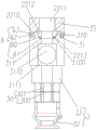
图4为本实施例的吸盘主体与连接头的剖视示意图。FIG. 4 is a schematic cross-sectional view of the suction cup body and the connecting head according to the present embodiment.
图中:1.新型吸盘组件,2.真空发生器,3.吸盘主体,20.壳体,21.上盖,22.底板,5.卡扣连接结构,220.连接通孔,221.连接头,6.快速连接结构,30.真空安全阀,50.扣勾,51.扣孔,202.上表面,200.空腔,4.真空发生器组件,201.环形凹槽,203.下底面,7.密封圈,8.环形凸块,2210.连接凹槽,2211.连接通道一,2212.倒圆台结构凸块,2213.放置凹槽,31.连接部,310.圆台凹槽,60.磁吸体一,61.磁吸体二,62.扣勾一,63.扣孔一,311.进出气通道,3110.运动空间,3111.活动阀芯,33.连接部一,32.吸附腔,300.中空状通道,301.内部阀门,210.真空进气口,211.连接螺纹孔,204.进气口,205.消声器连接孔。In the picture: 1. New suction cup assembly, 2. Vacuum generator, 3. Suction cup body, 20. Housing, 21. Upper cover, 22. Bottom plate, 5. Buckle connection structure, 220. Connection through hole, 221. Connection Head, 6. Quick connect structure, 30. Vacuum safety valve, 50. Buckle hook, 51. Buckle hole, 202. Upper surface, 200. Cavity, 4. Vacuum generator assembly, 201. Ring groove, 203. Lower Bottom surface, 7. Seal ring, 8. Ring bump, 2210. Connecting groove, 2211. Connecting
具体实施方式Detailed ways
以下所述仅为本实用新型的较佳实施例,并不因此而限定本发明的保护范围。The following descriptions are only preferred embodiments of the present invention, and therefore do not limit the protection scope of the present invention.
实施例,参见附图1~图4,一种新型吸盘组件1包括真空发生器2及多个吸盘主体3,所述真空发生器2包括壳体20、上盖21及底板22,所述上盖21设置在所述壳体22上方,所述底板22设置在所述壳体20下方,所述壳体20内设有真空发生器组件4,所述壳体20与上盖21之间设有卡扣连接结构5,所述底板22设有多个连接通孔220,所述多个连接通孔220与所述壳体20内连通,多个所述连接通孔220均设有连接头221,所述吸盘主体3设置在所述连接头221下方,所述连接头221与所述吸盘主体3之间快速连接结构6,多个所述吸盘主体3均设有真空安全阀30,所述吸盘主体3、真空安全阀30及壳体20内相连通,用于气体的流动。In an embodiment, referring to FIGS. 1 to 4 , a novel suction cup assembly 1 includes a vacuum generator 2 and a plurality of
所述卡扣连接结构5包括多个扣勾50及多个扣孔51,多个所述扣孔51设置在所述壳体20上表面202边缘,多个所述扣勾50设置在所述上盖21下方的四个侧面上,所述扣孔51与扣孔51之间间距一段距离,并沿着壳体20上表面边缘路径阵列分布,所述扣勾50与扣勾50之间间距一段距离,并沿着上盖21底面边缘路径阵列分布在上盖21的侧面,所述上盖21通过卡扣连接结构6连接在所述壳体20上方,所述底板22设有螺钉,所述螺钉将底板22固定连接在壳体20下方,所述壳体20设有空腔200,所述真空发生器组件4设置在空腔200内,所述卡扣连接结构6便于壳体20与上盖21的快速安装及拆卸,从而便于对壳体20内部及真空发生器组件4进行清理及维护更换。The
所述壳体20设有两环形凹槽201,两所述环形凹槽201分别设置在所述壳体20的上表面202及下底面203,所述环形凹槽201内均设有密封圈7,所述上盖21底面及底板22上表面均设有环形凸块8,所述环形凸块8分别与所述环形凹槽201配合连接,从而提高密封性,从而保证密封效果,防止出现漏气的情况出现。The
多个所述连接头221均设有连接凹槽2210及连接通道一2211,所述连接凹槽2210内设有倒圆台结构凸块2212,所述连接通道一2211贯穿倒圆台结构凸块2212,所述倒圆台结构凸块2212底部设有放置凹槽2213,所述吸盘主体3设有连接部31,所述连接部31连接时插入到所述连接凹槽2210内,所述连接部31设有与倒圆台结构凸块2212配合连接的圆台凹槽310,所述圆台结构310的横截面为倒梯形结构,所述圆台凹槽310底面设有放置凹槽一3100,所述圆台凹槽310的斜面设有密封圈,所述倒圆台结构凸块2212配合与圆台凹槽310连接,该结构用于吸盘主体3与连接头221连接时的密封,并配合密封圈实现双重密封效果,提高密封性。A plurality of the connecting
所述快速连接结构6包括磁吸体一60、磁吸体二61、多个扣勾一62及多个扣孔一63,所述磁吸体一60设置在所述倒圆台结构凸块2212的放置凹槽2213内,所述磁吸体二61设置在所述圆台凹槽310底面的放置凹槽一3100内,多个所述扣勾一62设置在所述连接部31外侧,多个所述扣孔一63设在所述连接凹槽2210内侧,所述连接部31通过多个扣勾一62分别与所述连接凹槽2210的多个扣孔一63配合连接,所述磁吸体一60与磁吸体二61用于吸盘主体3快速定位连接到连接头221下方,所述多个扣勾一62及多个扣孔一63用于吸盘主体3稳定的固定在连接头221下方,所述快速连接结构6用于吸盘主体3与连接头221的快速连接及拆卸,拆卸时,通过扣孔一63将扣勾一62朝中心位置顶,扣勾一62即可脱离扣孔一62,从而将吸盘主体3快速拆卸。The
所述连接部31设置在吸盘主体3上方,所述连接部31内设有进出气通道311,所述进出气通道311与所述连接通道一2211连通,所述进出气通道311设有运动空间3110,所述运动空间3110设有活动阀芯3111,所述活动阀芯3111为球体结构,所述活动阀芯3111可沿着运动空间3110上下移动,当抽气到一定程度时自动关闭连接部31的进出气通道311,即使新型吸盘组件1的一个吸盘主体3吸空,或物品表面凹凸不平导致吸盘主体3没有完全真空吸附物品,其它吸盘主体3也能正常工作,当不吸附时,活动阀芯3111在重力作用掉下时不会关闭所述气路流通口311。The connecting
所述吸盘主体3包括吸盘腔32及连接部一33,所述连接部一33设置在所述连接部31下方,所述真空安全阀30设置在所述吸盘腔32及连接部一33之间,所述真空安全阀30设有中空状通道300及内部阀门301,所述吸盘腔32及连接部一33均设有连通通道一,所述真空安全阀30具有吸盘腔32的下部物件的功能,并根据下部物件的有无来决定内部阀门301是否单向导通。正常情况下,当所述吸盘腔32的下部没有板材作为吸附料时,经过所述吸盘腔32的下部四周进入到所述真空安全阀30的气流较大,其产生的压力与所述真空安全阀30的内部阀门301受到的弹簧作用力大小相同且方向相反,二者处于作用平衡状态;当所述吸盘腔32的下部完全位于所述吸料上部时,经过所述吸盘腔32的下部四周进入到所述真空安全阀30的气流减少,这是所述真空安全阀30的内部阀门301在弹簧的作用下被推开,真空安全阀30将所述吸盘腔32内部抽成真空,吸盘腔32会将所述板材吸附起来。通过设置真空安全阀30及活动阀芯3111实现双重自动关闭或打开气路功能,保证吸附料的吸附稳定性。The
所述上盖21设有真空进气口210及连接螺纹孔211,所述连接螺纹孔211用于安装到移动设备上,所述真空进气口210用于与真空设备连接,所述壳体20后侧面设有进气口204,所述壳体20右侧面设有消声管连接孔,所述消声管连接孔用于真空发生器组件4与消声器连接。The
本实用新型通过设置卡扣连接结构便于壳体与上盖的快速安装及拆卸,从而便于对壳体内部及真空发生器组件进行清理及维护更换。通过设置快速连接结构用于吸盘主体与连接头的快速连接及拆卸,并且通过磁吸体一及磁吸体二便于便于快速对定位,减少安装步骤,从而提高安装或更换效率,保证后续的生产效率。通过设置真空安全阀及活动阀芯实现双重自动关闭或打开气路功能,当抽气到一定程度时自动关闭连接部的进出气通道,即使新型吸盘组件的一个吸盘主体吸空,或物品表面凹凸不平导致吸盘主体没有完全真空吸附物品,其它吸盘主体也能正常工作,当不吸附时,活动阀芯在重力作用掉下时不会关闭所述气路流通口,保证新型吸盘组件吸附料的吸附稳定性。The utility model facilitates the rapid installation and disassembly of the casing and the upper cover by providing the snap connection structure, thereby facilitating the cleaning, maintenance and replacement of the interior of the casing and the vacuum generator assembly. The quick connection structure is provided for the quick connection and disassembly of the suction cup body and the connecting head, and the magnetic attraction body 1 and the magnetic attraction body 2 facilitate quick positioning and reduce installation steps, thereby improving installation or replacement efficiency and ensuring subsequent production. efficiency. By setting the vacuum safety valve and the movable spool to achieve double automatic closing or opening of the air circuit function, when the air is pumped to a certain level, the air inlet and outlet channels of the connecting part are automatically closed, even if a suction cup body of the new suction cup assembly sucks air, or the surface of the item is uneven The unevenness causes the suction cup body to not completely vacuum the objects, and other suction cup bodies can also work normally. When it is not suctioned, the movable valve core will not close the air passage flow port when it falls under the action of gravity, so as to ensure the adsorption of the new suction cup assembly. stability.
本实用新型并不限于上述实施方式,采用与本实用新型上述实施例相同或近似结构或装置,而得到的其他用于新型吸盘组件,均在本实用新型的保护范围之内。The present invention is not limited to the above-mentioned embodiments, and other novel suction cup assemblies obtained by adopting the same or similar structures or devices as the above-mentioned embodiments of the present invention are all within the protection scope of the present invention.
Claims (7)
Priority Applications (1)
| Application Number | Priority Date | Filing Date | Title |
|---|---|---|---|
| CN201922460408.8U CN211496000U (en) | 2019-12-31 | 2019-12-31 | Novel sucking disc subassembly |
Applications Claiming Priority (1)
| Application Number | Priority Date | Filing Date | Title |
|---|---|---|---|
| CN201922460408.8U CN211496000U (en) | 2019-12-31 | 2019-12-31 | Novel sucking disc subassembly |
Publications (1)
| Publication Number | Publication Date |
|---|---|
| CN211496000U true CN211496000U (en) | 2020-09-15 |
Family
ID=72396905
Family Applications (1)
| Application Number | Title | Priority Date | Filing Date |
|---|---|---|---|
| CN201922460408.8U Active CN211496000U (en) | 2019-12-31 | 2019-12-31 | Novel sucking disc subassembly |
Country Status (1)
| Country | Link |
|---|---|
| CN (1) | CN211496000U (en) |
Cited By (4)
| Publication number | Priority date | Publication date | Assignee | Title |
|---|---|---|---|---|
| CN112830248A (en) * | 2021-02-05 | 2021-05-25 | 深圳市赛立鸿塑胶五金有限公司 | A suction cup fixture for LED light box processing |
| CN116081351A (en) * | 2022-11-11 | 2023-05-09 | 安徽美阅文化发展股份有限公司 | Feeding mechanism of automatic printing equipment |
| TWI811059B (en) * | 2022-08-12 | 2023-08-01 | 高加盛科技有限公司 | Adjustment structure of suction cup equipment |
| CN118850737A (en) * | 2024-07-24 | 2024-10-29 | 东台市绿华塑木科技有限公司 | A feeding device for a plastic wood floor production line |
-
2019
- 2019-12-31 CN CN201922460408.8U patent/CN211496000U/en active Active
Cited By (5)
| Publication number | Priority date | Publication date | Assignee | Title |
|---|---|---|---|---|
| CN112830248A (en) * | 2021-02-05 | 2021-05-25 | 深圳市赛立鸿塑胶五金有限公司 | A suction cup fixture for LED light box processing |
| CN112830248B (en) * | 2021-02-05 | 2022-04-01 | 深圳市赛立鸿塑胶五金有限公司 | Be applied to sucking disc anchor clamps of LED lamp house processing |
| TWI811059B (en) * | 2022-08-12 | 2023-08-01 | 高加盛科技有限公司 | Adjustment structure of suction cup equipment |
| CN116081351A (en) * | 2022-11-11 | 2023-05-09 | 安徽美阅文化发展股份有限公司 | Feeding mechanism of automatic printing equipment |
| CN118850737A (en) * | 2024-07-24 | 2024-10-29 | 东台市绿华塑木科技有限公司 | A feeding device for a plastic wood floor production line |
Similar Documents
| Publication | Publication Date | Title |
|---|---|---|
| CN103629415B (en) | Dynamic core assembly and use its solenoid valve | |
| CN103185150B (en) | Electromagnetic valve | |
| CN108098412B (en) | A seal-free modular vacuum fixture | |
| CN216098583U (en) | Novel vacuum chuck | |
| CN109585353B (en) | Suction cup and working method thereof | |
| CN212421027U (en) | Suction clamp | |
| CN204716700U (en) | A quick connector for a special-shaped plug-in machine | |
| TWM543156U (en) | Improved sucker assembly structure of suction device | |
| CN107120258B (en) | An inverted air compressor intake valve | |
| TWM543153U (en) | Suction device with quick release function | |
| CN211506168U (en) | A thimble assembly and thimble support device | |
| TWI552262B (en) | Bearing device | |
| CN222213197U (en) | Self-adaptive partition sucker | |
| CN220051887U (en) | Multi-point vacuum chuck | |
| CN217482071U (en) | Self-closing valve | |
| CN207183243U (en) | A kind of wafer bearing device | |
| WO2020233431A1 (en) | Air nozzle for vacuum bag | |
| CN220516563U (en) | Porous vacuum chuck | |
| CN215148437U (en) | A multi-point plane vacuum suction cup | |
| CN216883512U (en) | Vacuum adsorption device | |
| CN212461641U (en) | A sucking disc for wire jumper installation | |
| TWM643902U (en) | Electrostatic Chuck Quick Exhaust Structure for Semiconductor Process Vacuum Chamber | |
| CN108857981A (en) | Product positioning device and positioning method | |
| CN209136324U (en) | A kind of novel vaccum wall-breaking machine | |
| CN221942672U (en) | A gas flow control structure for a vacuum pump |
Legal Events
| Date | Code | Title | Description |
|---|---|---|---|
| GR01 | Patent grant | ||
| GR01 | Patent grant | ||
| TR01 | Transfer of patent right |
Effective date of registration: 20250407 Address after: No. 41 Yuning North Road, Hengli Town, Dongguan City, Guangdong Province 523000 Patentee after: Baika (Dongguan) Vacuum Technology Co.,Ltd. Country or region after: China Address before: Building B, No.372, Liaodong Road, Xixi village, Liaobu Town, Dongguan City, Guangdong Province 523000 Patentee before: Dongguan Baika pneumatic components Technology Co.,Ltd. Country or region before: China |
|
| TR01 | Transfer of patent right |