CN211494995U - Carrying protective box for communication equipment - Google Patents
Carrying protective box for communication equipment Download PDFInfo
- Publication number
- CN211494995U CN211494995U CN201922411988.1U CN201922411988U CN211494995U CN 211494995 U CN211494995 U CN 211494995U CN 201922411988 U CN201922411988 U CN 201922411988U CN 211494995 U CN211494995 U CN 211494995U
- Authority
- CN
- China
- Prior art keywords
- connecting rod
- communication equipment
- spring
- sliding block
- box body
- Prior art date
- Legal status (The legal status is an assumption and is not a legal conclusion. Google has not performed a legal analysis and makes no representation as to the accuracy of the status listed.)
- Active
Links
Images


Abstract
The utility model discloses a protective box for carrying communication equipment, which belongs to the technical field of communication equipment and comprises a box body, wherein a storage plate is arranged in the box body, a plurality of loop bars are fixed at the bottom of the storage plate, and fourth springs are respectively sleeved on the outer surfaces of the loop bars, the protective box for carrying communication equipment is provided with a chute, a first slider, a slide rail, a slide bar, a second slider, a second spring and a shaft pin, a user closes the box door after putting the communication equipment on the storage plate, the box door drives the second press plate to move through a second telescopic link, so that the communication equipment extrudes the first press plate, the first slider is driven to move upwards through the first connecting rod, the second connecting rod drives the second slider to move rightwards to compress the second spring, meanwhile, the second connecting rod rotates by taking the shaft pin as a fulcrum, so that the clamp plate moves downwards, thereby the clamp plate clamps the top of the communication equipment, and the clamping devices are not required to be manually adjusted by a user, so that the carrying efficiency of the communication equipment is greatly improved.
Description
Technical Field
The utility model relates to a communication equipment technical field specifically is a be used for communication equipment to carry protective housing.
Background
Communication equipment has been developed greatly in the twenty-first century, wireless communication equipment and wired communication equipment exist in an industrial control environment, and both the wired communication equipment and the wireless communication equipment need extra attention in the moving and transporting process, for some large-scale communication equipment, components installed in the whole equipment are expensive, and certain protective boxes are needed to be placed in the later moving and transporting process, so that the communication equipment can be installed in places as intact as possible.
Present be used for communication equipment to carry the protective housing, generally put into the protective housing with communication equipment is direct, then set up various damping device outside the protective housing and be used for the shock attenuation, but unable being applicable to the communication equipment of not unidimensional size, need form a complete set of protective housing of variation in size, lead to the practicality relatively poor, and present be used for communication equipment to carry the protective housing, when the user puts into communication equipment and takes out the protective housing, the position that needs manual regulation clamping device many times comes to fix communication equipment, complex operation, great influence the efficiency that communication equipment carried.
Disclosure of Invention
An object of the utility model is to provide a be used for communication equipment to carry protective case to propose the current communication equipment that is used for communication equipment to carry protective case and can't be applicable to not unidimensional size in solving above-mentioned background art, the practicality is relatively poor, and complex operation when putting into communication equipment and taking out the protective case, influence communication equipment and carry the problem of efficiency.
In order to achieve the above object, the utility model provides a following technical scheme: a carrying protective box for communication equipment comprises a box body, wherein a storage plate is arranged in the box body, a plurality of loop bars are fixed at the bottom of the storage plate, fourth springs are sleeved on the outer surfaces of the loop bars, the bottom end of each fourth spring is connected with the box body, a supporting block is installed below the inner part of the box body, a sliding groove is formed in the upper part of the inner wall of the box body, a first pressing plate is connected to the lower part of the inner wall of the box body through a first telescopic rod, a first connecting rod is connected to the middle of one side of the first pressing plate, a first sliding block is connected to the top end of the first connecting rod, one side of the first sliding block extends into the sliding groove, a second connecting rod is connected to the upper part of the outer surface of the first sliding block, a sliding rail is installed above the inner part of the box body, a sliding rod is fixed in the sliding rail, and a second sliding block and, one end of the second spring is connected with the second sliding block, the other end of the second spring is connected with the sliding rail, the top of the second connecting rod is rotatably connected with the second sliding block through a shaft pin, a clamping plate is installed at one end of the second connecting rod, a box door is installed at one side of the box body, one side of the box door is connected with a second pressing plate through a second telescopic rod, and a third spring is sleeved on the outer surface of the second telescopic rod.
Preferably, the outer surface of the first telescopic rod is sleeved with a first spring, and one end of the first spring is connected with the first pressing plate.
Preferably, the bottom end of the first connecting rod is hinged to the first pressing plate through a hinge, and the top end of the first connecting rod is rotatably connected to the first sliding block through a rotating shaft.
Preferably, one side of the first sliding block is matched with the sliding groove, and the first sliding block is connected with the sliding groove in a sliding mode.
Preferably, one end of the second connecting rod is hinged with the clamping plate through a hinge.
Preferably, the second connecting rod is in a shape of Chinese character 'ren'.
Preferably, the support block is made of a rubber material.
Compared with the prior art, the beneficial effects of the utility model are that: the protective box for carrying communication equipment is provided with a storage plate, a first telescopic rod, a first pressing plate, a first spring, a first connecting rod, a second connecting rod, a clamping plate, a second telescopic rod, a second pressing plate, a third spring, a fourth spring, a supporting block and a loop bar, wherein the first pressing plate can move left and right under the driving of the first telescopic rod and the first spring, and the second pressing plate can move left and right under the driving of a box door and the second telescopic rod, so that the two sides of the communication equipment are fixed, the communication equipment is prevented from shaking left and right when a vehicle accelerates or brakes, the clamping plate can move downwards under the driving of the first connecting rod and the second connecting rod, and the storage plate, the fourth spring and the supporting block are matched to fix the communication equipment up and down, so that the protective box can be suitable for communication equipment with different sizes, and the practicability of the protective box is greatly improved, when a user closes the box door, the box door drives the second pressing plate to move through the second telescopic rod, so that the communication equipment extrudes the first pressing plate, the first sliding block is driven to move upwards through the first connecting rod, the second connecting rod drives the second sliding block to move rightwards to compress the second spring, meanwhile, the second connecting rod rotates by taking the shaft pin as a fulcrum, so that the clamping plate moves downwards to fix the top of the communication equipment, when the user opens the box door to take out the communication equipment, the first pressing plate is reset leftwards under the driving of the first spring, the second spring resets to move the second sliding block leftwards, so that the clamping plate is driven to move upwards to reset, and then next loading and transportation can be carried out, by the structure, when the user puts in or takes out the communication equipment, the clamping devices are not required to be manually adjusted by a user, the operation is simple, and the carrying efficiency of the communication equipment is greatly improved.
Drawings
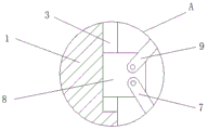
FIG. 1 is a schematic structural view of the present invention;
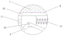
FIG. 2 is a schematic view of a box body of the present invention;
fig. 3 is an enlarged schematic view of a partial structure of the present invention a;
fig. 4 is an enlarged schematic view of a local structure of the present invention B.
In the figure: 1. a box body; 2. a storage plate; 3. a chute; 4. a first telescopic rod; 5. a first platen; 6. a first spring; 7. a first connecting rod; 8. a first slider; 9. a second connecting rod; 10. a slide rail; 11. a slide bar; 12. a second slider; 13. a second spring; 14. a splint; 15. a box door; 16. a second telescopic rod; 17. a second platen; 18. a third spring; 19. a shaft pin; 20. a fourth spring; 21. a support block; 22. a loop bar.
Detailed Description
The technical solutions in the embodiments of the present invention will be described clearly and completely with reference to the accompanying drawings in the embodiments of the present invention, and it is obvious that the described embodiments are only some embodiments of the present invention, not all embodiments. Based on the embodiments in the present invention, all other embodiments obtained by a person skilled in the art without creative work belong to the protection scope of the present invention.
In the present invention, unless otherwise expressly stated or limited, the terms "disposed," "mounted," "connected," "fixed," "sleeved," and the like are to be construed broadly, e.g., as either a fixed connection, a removable connection, or an integral part; can be mechanically or electrically connected; the two elements may be connected directly or indirectly through an intermediate medium, and the two elements may be connected internally or in an interaction relationship, and a person skilled in the art can understand the specific meaning of the above terms in the present invention according to specific situations.
Referring to fig. 1-4, the present invention provides a technical solution: a protective box for carrying communication equipment comprises a box body 1, a storage plate 2, a sliding groove 3, a first telescopic rod 4, a first pressing plate 5, a first spring 6, a first connecting rod 7, a first sliding block 8, a second connecting rod 9, a sliding rail 10, a sliding rod 11, a second sliding block 12, a second spring 13, a clamping plate 14, a box door 15, a second telescopic rod 16, a second pressing plate 17, a third spring 18, a shaft pin 19, a fourth spring 20, a supporting block 21 and a sleeve rod 22, wherein the storage plate 2 is arranged in the box body 1, a plurality of sleeve rods 22 are fixed at the bottom of the storage plate 2, the outer surfaces of the sleeve rods 22 are respectively sleeved with the fourth spring 20, the bottom end of the fourth spring 20 is connected with the box body 1, the supporting block 21 is arranged below the inner part of the box body 1, the sliding groove 3 is arranged above the inner wall of the box body 1, the lower part of the inner wall of the box body 1 is connected with the first pressing plate 5 through the first telescopic rod 4, the first connecting, the top end of the first connecting rod 7 is connected with a first sliding block 8, one side of the first sliding block 8 extends into the sliding chute 3, the upper part of the outer surface of the first sliding block 8 is connected with a second connecting rod 9, the upper part of the inner part of the box body 1 is provided with a sliding rail 10, the inner part of the sliding rail 10 is fixedly provided with a sliding rod 11, the outer surface of the sliding rod 11 is respectively sleeved with a second sliding block 12 and a second spring 13, one end of the second spring 13 is connected with the second sliding block 12, the other end of the second spring 13 is connected with the sliding rail 10, the top part of the second connecting rod 9 is rotatably connected with the second sliding block 12 through a shaft pin 19, one end of the second connecting rod 9 is provided with a clamping plate 14, one side of the box body 1 is provided with a box door 15, one side of the box door 15 is connected with a second pressing plate 17 through a second telescopic rod 16, the outer surface of the second telescopic rod 16 is sleeved with, the protection performance of the protection box is improved.
Referring to fig. 1, 2 and 3, a first spring 6 is sleeved on an outer surface of the first telescopic rod 4, one end of the first spring 6 is connected to the first pressing plate 5, a bottom end of a first connecting rod 7 is hinged to the first pressing plate 5 through a hinge, and a top end of the first connecting rod 7 is rotatably connected to the first sliding block 8 through a rotating shaft, so that the first pressing plate 5 can drive the first sliding block 8 to move up and down through the first connecting rod 7.
Referring to fig. 1 and 4, one side of the first sliding block 8 is adapted to the sliding groove 3, the first sliding block 8 is slidably connected to the sliding groove 3, and one end of the second connecting rod 9 is hinged to the clamping plate 14 through a hinge, so that the clamping plate 14 can clamp the communication device under the driving of the second connecting rod 9.
Referring to fig. 1 and 2, the second connecting rod 9 is shaped like a Chinese character 'ren', the supporting block 21 is made of rubber, and the supporting block 21 is arranged to prevent the storage board 2 from colliding with the box body 1 to cause damage to the communication equipment.
The working principle is as follows: when a user uses the protective box for carrying communication equipment, firstly, the box door 15 is opened, the communication equipment is placed on the object placing plate 2, then the box door 15 is closed, the box door 15 drives the second pressing plate 17 to move through the second telescopic rod 16, the communication equipment extrudes the first pressing plate 5 under the pushing of the second pressing plate 17, so that two sides of the communication equipment are fixed, the communication equipment is prevented from shaking left and right when a vehicle accelerates or brakes, the first pressing plate 5 moves left under the extrusion of the communication equipment, the first pressing plate 5 drives the first sliding block 8 to move upwards along the sliding groove 3 through the first connecting rod 7, the first sliding block 8 drives the second sliding block 12 through the second connecting rod 9, the second sliding block 12 moves right along the sliding rail 10 to compress the second spring 13, meanwhile, the second connecting rod 9 rotates by taking the shaft pin 19 as a fulcrum, so that the clamping plate 14 moves downwards, so that the clamping plate 14 fixes the top of the communication equipment, when a user opens the box door 15 to take out the communication equipment, the first pressing plate 5 is driven by the first spring 6 to reset leftwards, the second spring 13 resets to enable the second sliding block 12 to move leftwards, so that the clamping plate 14 is driven to move upwards to reset, each clamping device does not need to be manually adjusted by the user, and next loading and transportation can be carried out.
Although embodiments of the present invention have been shown and described, it will be appreciated by those skilled in the art that changes, modifications, substitutions and alterations can be made in these embodiments without departing from the principles and spirit of the invention, the scope of which is defined in the appended claims and their equivalents.
Claims (7)
1. A is used for communication equipment to carry protective case, includes box (1), its characterized in that: the article placing plate (2) is arranged in the box body (1), a plurality of loop bars (22) are fixed at the bottom of the article placing plate (2), a fourth spring (20) is sleeved on the outer surface of each loop bar (22), the bottom end of each fourth spring (20) is connected with the box body (1), a supporting block (21) is installed below the inner portion of the box body (1), a sliding groove (3) is formed in the upper portion of the inner wall of the box body (1), a first pressing plate (5) is connected below the inner wall of the box body (1) through a first telescopic rod (4), a first connecting rod (7) is connected to the middle of one side of the first pressing plate (5), a first sliding block (8) is connected to the top end of the first connecting rod (7), one side of the first sliding block (8) extends to the inner portion of the sliding groove (3), and a second connecting rod (9) is connected above the outer surface of the first sliding block (8), slide rail (10) are installed to the inside top of box (1), the inside of slide rail (10) is fixed with slide bar (11), second slider (12) and second spring (13) have been cup jointed respectively to the surface of slide bar (11), the one end of second spring (13) is connected with second slider (12), the other end of second spring (13) is connected with slide rail (10), the top of second connecting rod (9) is passed through pivot (19) and is rotated with second slider (12) and be connected, splint (14) are installed to the one end of second connecting rod (9), chamber door (15) are installed to one side of box (1), one side of chamber door (15) is connected with second clamp plate (17) through second telescopic link (16), the surface of second telescopic link (16) has cup jointed third spring (18).
2. A carrier case for a communication device as defined in claim 1, wherein: the outer surface of the first telescopic rod (4) is sleeved with a first spring (6), and one end of the first spring (6) is connected with the first pressing plate (5).
3. A carrier case for a communication device as defined in claim 1, wherein: the bottom end of the first connecting rod (7) is hinged to the first pressing plate (5) through a hinge, and the top end of the first connecting rod (7) is rotatably connected with the first sliding block (8) through a rotating shaft.
4. A carrier case for a communication device as defined in claim 1, wherein: one side of the first sliding block (8) is matched with the sliding groove (3), and the first sliding block (8) is connected with the sliding groove (3) in a sliding mode.
5. A carrier case for a communication device as defined in claim 1, wherein: one end of the second connecting rod (9) is hinged with the clamping plate (14) through a hinge.
6. A carrier case for a communication device as defined in claim 1, wherein: the second connecting rod (9) is in a herringbone shape.
7. A carrier case for a communication device as defined in claim 1, wherein: the supporting block (21) is made of rubber materials.
Priority Applications (1)
| Application Number | Priority Date | Filing Date | Title |
|---|---|---|---|
| CN201922411988.1U CN211494995U (en) | 2019-12-28 | 2019-12-28 | Carrying protective box for communication equipment |
Applications Claiming Priority (1)
| Application Number | Priority Date | Filing Date | Title |
|---|---|---|---|
| CN201922411988.1U CN211494995U (en) | 2019-12-28 | 2019-12-28 | Carrying protective box for communication equipment |
Publications (1)
| Publication Number | Publication Date |
|---|---|
| CN211494995U true CN211494995U (en) | 2020-09-15 |
Family
ID=72395912
Family Applications (1)
| Application Number | Title | Priority Date | Filing Date |
|---|---|---|---|
| CN201922411988.1U Active CN211494995U (en) | 2019-12-28 | 2019-12-28 | Carrying protective box for communication equipment |
Country Status (1)
| Country | Link |
|---|---|
| CN (1) | CN211494995U (en) |
Cited By (5)
| Publication number | Priority date | Publication date | Assignee | Title |
|---|---|---|---|---|
| CN112423505A (en) * | 2020-11-17 | 2021-02-26 | 郭炎伟 | Anti-theft device protection device and use method thereof |
| CN112492419A (en) * | 2020-11-19 | 2021-03-12 | 嘉善富庆电子有限公司 | External audio amplifier of anti-vibration cylinder |
| CN113602646A (en) * | 2021-09-03 | 2021-11-05 | 潍坊职业学院 | Dustproof turnover case of waste material compression in non-woven fabrics production process |
| WO2022088004A1 (en) * | 2020-10-30 | 2022-05-05 | 张婷婷 | Electric motor transporting and protecting device |
| CN114771396A (en) * | 2022-05-09 | 2022-07-22 | 安徽银汉机电科技有限公司 | Safety device for electric appliance and circuit element |
-
2019
- 2019-12-28 CN CN201922411988.1U patent/CN211494995U/en active Active
Cited By (8)
| Publication number | Priority date | Publication date | Assignee | Title |
|---|---|---|---|---|
| WO2022088004A1 (en) * | 2020-10-30 | 2022-05-05 | 张婷婷 | Electric motor transporting and protecting device |
| CN112423505A (en) * | 2020-11-17 | 2021-02-26 | 郭炎伟 | Anti-theft device protection device and use method thereof |
| CN112492419A (en) * | 2020-11-19 | 2021-03-12 | 嘉善富庆电子有限公司 | External audio amplifier of anti-vibration cylinder |
| CN112492419B (en) * | 2020-11-19 | 2022-09-09 | 深圳市数博环球电子有限公司 | External audio amplifier of anti-vibration cylinder |
| CN113602646A (en) * | 2021-09-03 | 2021-11-05 | 潍坊职业学院 | Dustproof turnover case of waste material compression in non-woven fabrics production process |
| CN113602646B (en) * | 2021-09-03 | 2022-12-20 | 潍坊职业学院 | Dustproof turnover case of waste material compression in non-woven fabrics production process |
| CN114771396A (en) * | 2022-05-09 | 2022-07-22 | 安徽银汉机电科技有限公司 | Safety device for electric appliance and circuit element |
| CN114771396B (en) * | 2022-05-09 | 2023-06-09 | 安徽银汉机电科技有限公司 | Safety device for electric appliance and circuit element |
Similar Documents
| Publication | Publication Date | Title |
|---|---|---|
| CN211494995U (en) | Carrying protective box for communication equipment | |
| CN213323168U (en) | Conveyer of commodity circulation supply chain | |
| CN107487578A (en) | A kind of electronic product accommodation exhibiting device | |
| CN208665995U (en) | It is a kind of for transporting the box for material circulation of plastic grain | |
| CN108809240B (en) | Solar photovoltaic power generation board easy to store | |
| CN210445971U (en) | Novel nursing tool arrangement box | |
| CN201841548U (en) | Grip and mechanical arm for high-speed boxes | |
| CN208963123U (en) | A kind of lead storage battery transport device | |
| CN207329764U (en) | A kind of straight line transfer platform of PV glass panel automatic charging machine | |
| CN211831577U (en) | PLC switch board for metallurgical industry | |
| CN110962894A (en) | Liftable commodity circulation shallow | |
| CN207290358U (en) | A kind of groover feeding clip mechanism | |
| CN106275750B (en) | A kind of old and useless newspaper fixing device | |
| CN214241849U (en) | Be applicable to fixed packing plant of cabinet body class transportation | |
| CN211336010U (en) | Material turnover vehicle for building | |
| CN208411791U (en) | A kind of citrus potting handling device | |
| CN208484351U (en) | A kind of screen printing device producing mobile phone glass film | |
| CN215121471U (en) | Protection device for spectrum instrument | |
| CN212034573U (en) | Portable intelligent diagnosis device for machine learning | |
| CN214747876U (en) | Worm wheel backlash detects frock | |
| CN220615874U (en) | Automatic unloading trolley for logistics transportation | |
| CN209080270U (en) | A kind of lens collar wrapping tool | |
| CN217020320U (en) | Maintenance tool storage device | |
| CN211496091U (en) | Copper-clad plate powder charging bag supporting device | |
| CN216270978U (en) | Environmental pollution treating agent transportation equipment |
Legal Events
| Date | Code | Title | Description |
|---|---|---|---|
| GR01 | Patent grant | ||
| GR01 | Patent grant | ||
| TR01 | Transfer of patent right | ||
| TR01 | Transfer of patent right |
Effective date of registration: 20221020 Address after: 337000 Laozhan Community, Bayi Street, Anyuan District, Pingxiang City, Jiangxi Province Patentee after: Jiangxi Anda Information Industry Co.,Ltd. Address before: Room cx452, 4 / F phase I and 4 / F phase II, No.8 complex building, No.1 Taozhuang, Tianhe District, Guangzhou, Guangdong, 510599 Patentee before: Guangdong Zhijiu Information Technology Co.,Ltd. |