CN211494240U - A front traction beam for a truck frame - Google Patents
A front traction beam for a truck frame Download PDFInfo
- Publication number
- CN211494240U CN211494240U CN201922325088.5U CN201922325088U CN211494240U CN 211494240 U CN211494240 U CN 211494240U CN 201922325088 U CN201922325088 U CN 201922325088U CN 211494240 U CN211494240 U CN 211494240U
- Authority
- CN
- China
- Prior art keywords
- front traction
- connecting bracket
- support
- truck frame
- traction seat
- Prior art date
- Legal status (The legal status is an assumption and is not a legal conclusion. Google has not performed a legal analysis and makes no representation as to the accuracy of the status listed.)
- Active
Links
Images


Landscapes
- Body Structure For Vehicles (AREA)
Abstract
本实用新型提供了一种卡车车架用前牵引横梁,涉及汽车零部件领域,包括横梁连接支架、横梁支撑管梁和横梁前牵引座;所述横梁连接支架包括两个L形支架,所述横梁前牵引座位于两个L形支架之间,所述横梁支撑管梁的一端与横梁连接支架连接,所述横梁支撑管梁的另一端与横梁前牵引座连接;所述横梁连接支架的一侧与横梁支撑管梁连接,所述横梁连接支架的另一侧与车架和前围支撑大铸件连接固定。该方案通过采用横梁连接支架、横梁支撑管梁与横梁前牵引座连接,压缩前牵引横梁的占用空间,并使横梁连接支架直接与车架和前围支撑大铸件连接,在满足整车前牵引要求的同时显著提升整车布置空间。车架前端可利用空间,安全可靠,适宜推广应用。
The utility model provides a front traction beam for a truck frame, which relates to the field of auto parts, comprising a beam connecting bracket, a beam supporting pipe beam and a front traction seat for the beam; the beam connecting bracket comprises two L-shaped brackets, and the The front traction seat of the beam is located between the two L-shaped brackets, one end of the beam supporting pipe beam is connected with the beam connecting bracket, and the other end of the beam supporting pipe beam is connected with the front traction seat of the beam; one end of the beam connecting bracket is connected. The side is connected with the cross beam support pipe beam, and the other side of the cross beam connecting bracket is connected and fixed with the frame and the front wall supporting large casting. This scheme uses the beam connecting bracket, the beam supporting tube beam to connect with the front traction seat of the beam, compresses the space occupied by the front traction beam, and makes the beam connecting bracket directly connected to the frame and the large casting of the front wall support. It can significantly increase the layout space of the vehicle when required. The front end of the frame has available space, is safe and reliable, and is suitable for popularization and application.
Description
技术领域technical field
本实用新型属于汽车零部件领域,具体涉及一种卡车车架用前牵引横梁。The utility model belongs to the field of auto parts, in particular to a front traction beam for a truck frame.
背景技术Background technique
随着国六发动机的逐步上场以及市场对发动机马力需求的提高,发动机对整车冷却系统的要求也随之变大,为此不得不匹配更大规格的发动机风扇和更大尺寸的散热器。如图1所示,原有前牵引横梁布置形式采用整梁装配,整梁布置外加其他配件占用空间较大,已经无法满足整车布置要求。With the gradual introduction of the National VI engine and the increase in the market's demand for engine horsepower, the engine's requirements for the vehicle's cooling system have also increased. For this reason, it has to match a larger-sized engine fan and a larger-sized radiator. As shown in Figure 1, the original front traction beam layout adopts the whole beam assembly, and the whole beam layout plus other accessories takes up a lot of space, which can no longer meet the requirements of the vehicle layout.
因此,需新开发一种通用性强并且安装方便,可以显著提升整车布置空间的前牵引横梁总成。Therefore, it is necessary to develop a new front traction beam assembly with strong versatility and convenient installation, which can significantly increase the layout space of the whole vehicle.
实用新型内容Utility model content
针对现有技术的上述不足,本实用新型提供一种卡车车架用前牵引横梁,以解决上述技术问题。In view of the above-mentioned deficiencies of the prior art, the present invention provides a front traction beam for a truck frame to solve the above-mentioned technical problems.
一种卡车车架用前牵引横梁,包括横梁连接支架、横梁支撑管梁和横梁前牵引座;所述横梁连接支架包括两个L形支架,所述横梁前牵引座位于两个L形支架之间,所述横梁支撑管梁的一端与横梁连接支架连接,所述横梁支撑管梁的另一端与横梁前牵引座连接;所述横梁连接支架的一侧与横梁支撑管梁连接,所述横梁连接支架的另一侧与车架和前围支撑大铸件连接固定。A front traction beam for a truck frame includes a beam connecting bracket, a beam supporting pipe beam and a front traction seat for the beam; the beam connecting bracket includes two L-shaped brackets, and the front traction seat for the beam is located between the two L-shaped brackets. one end of the beam supporting pipe beam is connected with the beam connecting bracket, the other end of the beam supporting pipe beam is connected with the front traction seat of the beam; one side of the beam connecting bracket is connected with the beam supporting pipe beam, the beam The other side of the connecting bracket is connected and fixed with the frame and the large casting of the front wall support.
进一步的,包括保险杠安装支座,所述保险杠安装支座固定在横梁支撑管梁上,所述保险杠安装支座与保险杠底座连接。Further, it includes a bumper installation support, the bumper installation support is fixed on the beam support pipe beam, and the bumper installation support is connected with the bumper base.
进一步的,所述保险杠安装支座为U型连接板结构。Further, the bumper mounting support is a U-shaped connecting plate structure.
进一步的,包括前围上车踏步支座,所述前围上车踏步支座固定在横梁支撑管梁上。Further, it includes a front wall stepping support, and the front wall stepping support is fixed on the cross beam support pipe beam.
进一步的,所述前围上车踏步支座为U型连接板结构。Further, the front wall upper step support is a U-shaped connecting plate structure.
进一步的,所述横梁前牵引座为长方体中空结构,所述横梁前牵引座的中部设置有前牵引钩固定螺纹孔。Further, the front traction seat of the cross beam is a hollow cuboid structure, and the middle part of the front traction seat of the cross beam is provided with a screw hole for fixing the front traction hook.
本实用新型的有益效果在于,本实用新型提供的卡车车架用前牵引横梁,通过采用横梁连接支架、横梁支撑管梁与横梁前牵引座连接,压缩前牵引横梁的占用空间,并使横梁连接支架直接与车架和前围支撑大铸件连接,本实用新型在满足整车前牵引要求的同时显著提升整车布置空间。该实用新型强度高,车架前端可利用空间大,安全可靠,适宜推广应用。The beneficial effect of the utility model is that the front traction beam for the truck frame provided by the utility model is connected to the front traction seat of the beam by adopting the beam connecting bracket and the beam support pipe beam, thereby compressing the occupied space of the front traction beam and connecting the beams. The bracket is directly connected with the frame and the front wall supporting large casting, and the utility model not only meets the front traction requirements of the whole vehicle, but also significantly increases the layout space of the whole vehicle. The utility model has high strength, large usable space at the front end of the frame, safety and reliability, and is suitable for popularization and application.
此外,本实用新型设计原理可靠,结构简单,具有非常广泛的应用前景。In addition, the design principle of the utility model is reliable, the structure is simple, and the utility model has a very wide application prospect.
附图说明Description of drawings
为了更清楚地说明本实用新型实施例或现有技术中的技术方案,下面将对实施例或现有技术描述中所需要使用的附图作简单地介绍,显而易见地,对于本领域普通技术人员而言,在不付出创造性劳动的前提下,还可以根据这些附图获得其他的附图。In order to more clearly illustrate the embodiments of the present invention or the technical solutions in the prior art, the following briefly introduces the accompanying drawings that need to be used in the description of the embodiments or the prior art. It is obvious to those skilled in the art that In other words, on the premise of no creative work, other drawings can also be obtained based on these drawings.
图1是现有技术前牵引横梁结构示意图。FIG. 1 is a schematic structural diagram of a front traction beam in the prior art.
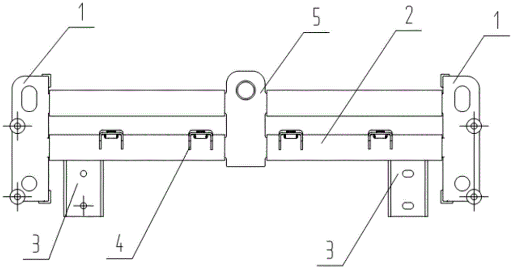
图2是本实用新型卡车车架用前牵引横梁的主视结构示意图1。FIG. 2 is a
图3是本实用新型卡车车架用前牵引横梁的俯视结构示意图2。3 is a schematic
图4是本实用新型卡车车架用前牵引横梁的安装结构示意图。4 is a schematic diagram of the installation structure of the front traction beam for the truck frame of the present invention.
图中,1、横梁连接支架,2、横梁支撑管梁,3、保险杠安装支座,4、前围上车踏步支座,5、横梁前牵引座,6、车架,7、前围支撑大铸件,8、保险杠底座。In the figure, 1. Beam connecting bracket, 2. Beam supporting tube beam, 3. Bumper mounting support, 4. Front wall stepping support, 5. Beam front traction seat, 6. Frame, 7. Front wall Support large castings, 8. Bumper base.
具体实施方式Detailed ways
为了使本技术领域的人员更好地理解本实用新型中的技术方案,下面将结合本实用新型实施例中的附图,对本实用新型实施例中的技术方案进行清楚、完整地描述,显然,所描述的实施例仅仅是本实用新型一部分实施例,而不是全部的实施例。基于本实用新型中的实施例,本领域普通技术人员在没有做出创造性劳动前提下所获得的所有其他实施例,都应当属于本实用新型保护的范围。In order to make those skilled in the art better understand the technical solutions of the present invention, the following will clearly and completely describe the technical solutions in the embodiments of the present invention with reference to the accompanying drawings in the embodiments of the present invention. Obviously, The described embodiments are only some, but not all, embodiments of the present invention. Based on the embodiments of the present invention, all other embodiments obtained by persons of ordinary skill in the art without creative work shall fall within the protection scope of the present invention.
本实用新型是一种卡车车架用前牵引横梁总成,如图2-4所示,是由横梁连接支架1、横梁支撑管梁2、保险杠安装支座3、前围上车踏步支座4和横梁前牵引座5相互焊接组成,并通过螺栓与车架6和前围支撑大铸件7连接固定。The utility model is a front traction beam assembly for a truck frame. As shown in Figures 2-4, the utility model is composed of a
横梁连接支架1包括两个铸造而成的L形支架,所述横梁前牵引座5位于两个 L形支架之间,所述横梁支撑管梁2的一端与横梁连接支架1连接,所述横梁支撑管梁2的另一端与横梁前牵引座5连接;所述横梁连接支架1的一侧与横梁支撑管梁连接,所述横梁连接支架1的另一侧与车架6和前围支撑大铸件7连接固定。The
横梁支撑管梁2是由7mm管梁切割而成,两侧分别与横梁连接支架1和横梁前牵引座5焊接固定。The beam
保险杠安装支座3是由4mm厚钢板折弯而成的U型连接板,焊接固定在横梁支撑管梁2上,并通过螺栓固定保险杠底座8。The
前围上车踏步支座4是由4mm厚钢板折弯而成的U型连接板,焊接固定在横梁支撑管梁2上,并焊有螺母用于安装前围上车踏板。The front wall boarding step support 4 is a U-shaped connecting plate formed by bending a 4mm thick steel plate, which is welded and fixed on the beam
横梁前牵引座5是铸造而成的长方体中空铸件,支座中部带有前牵引钩固定螺纹孔,在保证强度的前提下在铸件内部留有中空设计进行零件轻量化,与横梁支撑管梁2焊接固定。The
本实用新型的有益效果在于,本实用新型提供的卡车车架6用前牵引横梁,通过采用横梁连接支架1、横梁支撑管梁与横梁前牵引座5连接,压缩前牵引横梁的占用空间,并使横梁连接支架1直接与车架6和前围支撑大铸件7连接,本实用新型在满足整车前牵引要求的同时显著提升整车布置空间。该实用新型强度高,车架6前端可利用空间大,安全可靠,适宜推广应用。The beneficial effect of the present invention is that, the front traction beam for the
此外,本实用新型设计原理可靠,结构简单,具有非常广泛的应用前景。In addition, the design principle of the utility model is reliable, the structure is simple, and the utility model has a very wide application prospect.
尽管通过参考附图并结合优选实施例的方式对本实用新型进行了详细描述,但本实用新型并不限于此。在不脱离本实用新型的精神和实质的前提下,本领域普通技术人员可以对本实用新型的实施例进行各种等效的修改或替换,而这些修改或替换都应在本实用新型的涵盖范围内/任何熟悉本技术领域的技术人员在本实用新型揭露的技术范围内,可轻易想到变化或替换,都应涵盖在本实用新型的保护范围之内。因此,本实用新型的保护范围应所述以权利要求的保护范围为准。Although the present invention has been described in detail with reference to the accompanying drawings and in conjunction with the preferred embodiments, the present invention is not limited thereto. Without departing from the spirit and essence of the present invention, those of ordinary skill in the art can make various equivalent modifications or replacements to the embodiments of the present invention, and these modifications or replacements should all fall within the scope of the present invention Any person skilled in the art who is familiar with the technical field can easily think of changes or substitutions within the technical scope disclosed by the present invention, which should be covered by the protection scope of the present invention. Therefore, the protection scope of the present invention should be based on the protection scope of the claims.
Claims (6)
Priority Applications (1)
| Application Number | Priority Date | Filing Date | Title |
|---|---|---|---|
| CN201922325088.5U CN211494240U (en) | 2019-12-19 | 2019-12-19 | A front traction beam for a truck frame |
Applications Claiming Priority (1)
| Application Number | Priority Date | Filing Date | Title |
|---|---|---|---|
| CN201922325088.5U CN211494240U (en) | 2019-12-19 | 2019-12-19 | A front traction beam for a truck frame |
Publications (1)
| Publication Number | Publication Date |
|---|---|
| CN211494240U true CN211494240U (en) | 2020-09-15 |
Family
ID=72418198
Family Applications (1)
| Application Number | Title | Priority Date | Filing Date |
|---|---|---|---|
| CN201922325088.5U Active CN211494240U (en) | 2019-12-19 | 2019-12-19 | A front traction beam for a truck frame |
Country Status (1)
| Country | Link |
|---|---|
| CN (1) | CN211494240U (en) |
Cited By (1)
| Publication number | Priority date | Publication date | Assignee | Title |
|---|---|---|---|---|
| CN113335382A (en) * | 2021-06-17 | 2021-09-03 | 东风柳州汽车有限公司 | Separation arrangement structure of pipeline at cross beam of commercial vehicle |
-
2019
- 2019-12-19 CN CN201922325088.5U patent/CN211494240U/en active Active
Cited By (2)
| Publication number | Priority date | Publication date | Assignee | Title |
|---|---|---|---|---|
| CN113335382A (en) * | 2021-06-17 | 2021-09-03 | 东风柳州汽车有限公司 | Separation arrangement structure of pipeline at cross beam of commercial vehicle |
| CN113335382B (en) * | 2021-06-17 | 2022-06-07 | 东风柳州汽车有限公司 | Separation arrangement structure of pipeline at cross beam of commercial vehicle |
Similar Documents
| Publication | Publication Date | Title |
|---|---|---|
| CN205836565U (en) | Electric-powered assembly and the vehicle with it | |
| CN109774446B (en) | A power battery installation structure for electric vehicles | |
| CN205010322U (en) | Installing support subassembly on car front longitudinal | |
| CN201473988U (en) | Mounting device for suspending and heat radiation system of miniature hydraulic excavator | |
| CN205871728U (en) | Vehicle and refrigerating module thereof | |
| CN110843495A (en) | New forms of energy freight train battery package support frame | |
| CN110789321B (en) | Multifunctional bearing device suitable for electric vehicle | |
| CN109436094B (en) | Auxiliary frame for integrated installation of electric automobile accessories and connecting system thereof | |
| CN218316234U (en) | An all-in-one bracket for electric commercial vehicles | |
| CN211809850U (en) | A trailer aid | |
| CN108482087A (en) | The aluminium alloy power assembly mounting device of pure electric automobile | |
| CN210881618U (en) | Mounting brackets and vehicles for vehicles | |
| CN223327640U (en) | Air switch support and frame of electric motor car | |
| CN217944897U (en) | Integrated mounting frame and operation machine | |
| CN221316119U (en) | Integrated air compressor machine supporting structure | |
| CN207015337U (en) | A kind of new vavuum pump mounting bracket | |
| CN210971330U (en) | A rear stabilizer auxiliary fixing device | |
| CN205225511U (en) | Novel empty filter supporting structure of passenger train | |
| CN222391539U (en) | Mounting bracket of electric inflating pump air filter element of new energy commercial vehicle | |
| CN222988320U (en) | Integrated aluminum alloy casting main frame | |
| CN212828890U (en) | Controller and charger installation coupling mechanism | |
| CN202952940U (en) | Oil pump bracket | |
| CN221819818U (en) | A fixing part of bottom-mounted traction device of electric vehicle | |
| CN220298423U (en) | Semitrailer toolbox assembly structure | |
| CN206242852U (en) | The fixed structure of mount point under a kind of condenser |
Legal Events
| Date | Code | Title | Description |
|---|---|---|---|
| GR01 | Patent grant | ||
| GR01 | Patent grant |