CN211489677U - Reverse boring cutter for hub shaft hole - Google Patents
Reverse boring cutter for hub shaft hole Download PDFInfo
- Publication number
- CN211489677U CN211489677U CN201922050860.7U CN201922050860U CN211489677U CN 211489677 U CN211489677 U CN 211489677U CN 201922050860 U CN201922050860 U CN 201922050860U CN 211489677 U CN211489677 U CN 211489677U
- Authority
- CN
- China
- Prior art keywords
- cutter
- shaft hole
- plane
- tip
- cylindricality
- Prior art date
- Legal status (The legal status is an assumption and is not a legal conclusion. Google has not performed a legal analysis and makes no representation as to the accuracy of the status listed.)
- Active
Links
- 230000007704 transition Effects 0.000 claims description 4
- 238000012545 processing Methods 0.000 abstract description 10
- 238000003754 machining Methods 0.000 abstract description 6
- 238000005520 cutting process Methods 0.000 description 3
- 230000002349 favourable effect Effects 0.000 description 3
- 238000000034 method Methods 0.000 description 3
- 230000008569 process Effects 0.000 description 3
- 238000012958 reprocessing Methods 0.000 description 3
- 238000009434 installation Methods 0.000 description 2
- 238000004519 manufacturing process Methods 0.000 description 2
- 230000004048 modification Effects 0.000 description 2
- 238000012986 modification Methods 0.000 description 2
- 238000012797 qualification Methods 0.000 description 2
- 229910000838 Al alloy Inorganic materials 0.000 description 1
- 230000009286 beneficial effect Effects 0.000 description 1
- 238000007599 discharging Methods 0.000 description 1
- 230000006872 improvement Effects 0.000 description 1
Images

Landscapes
- Drilling And Boring (AREA)
Abstract
The utility model provides a wheel hub shaft hole reverse boring cutter, including clamping part, toper portion, cylindricality portion and tip, its characterized in that, a terminal surface of clamping part with the bottom face of toper portion links to each other, the top face of toper portion with the one end of cylindricality portion links to each other, the other end of cylindricality portion with the tip links to each other, be equipped with the blade mounting groove on the tip. The utility model provides a pair of anti-boring cutter in wheel hub shaft hole uses the toper portion to increase the length of cutter, improves the structural strength of cutter, reduce because of the longer cutter problem that shakes of taking place in the course of working of cutter, can stretch into in darker or less shaft hole through cylindricality portion, carry out reverse bore hole processing to the shaft hole internal face of keeping away from the cutter end in shaft hole, the both ends in the shaft hole of the product after making the processing keep same coordinate system, eliminate the axiality deviation of dead eye by a wide margin, improve product machining precision, improve the product percent of pass.
Description
Technical Field
The utility model relates to the field of machining, particularly, relate to a reverse boring cutter in wheel hub shaft hole.
Background
Bearings are mounted at two ends of an axle hole of an aluminum alloy hub of a motorcycle and an electric bicycle, in the reprocessing process, the axle hole at one end is usually processed firstly, then another axle hole is processed by taking the axle hole as a fixed core, but in the actual production process, the fixed core and the axle hole have a gap, the fixed core is worn after being used for a period of time, the matching size of the fixed core and the processed axle hole is increased, so that after the axle hole is used as a positioning reference for positioning and clamping, after the axle hole at the other end is processed, the coaxiality deviation of two bearing holes exists, the coaxiality deviation required by part of motorcycle manufacturers is less than 0.05mm, the tolerance requirement is very high, in the actual production process, the used fixed core has a precision tolerance of 0.02mm, the clamping has a certain gap, the coaxiality of the two final axle holes hardly meets the requirement, the qualification rate is very low, and therefore, a new idea is urgently needed to improve the coaxiality of the two shaft holes and improve the qualification rate of products.
Disclosure of Invention
The present invention aims at least solving one of the technical problems existing in the prior art or the related art.
Therefore, an object of the utility model is to provide a wheel hub shaft hole reverse boring cutter, including clamping part, toper portion, cylindricality portion and tip, a terminal surface of clamping part links to each other with the bottom face of toper portion, and the top face of toper portion links to each other with the one end of cylindricality portion, and the other end of cylindricality portion links to each other with the tip, is equipped with the blade mounting groove on the tip.
The utility model provides a pair of anti-boring cutter in wheel hub shaft hole, use the toper portion to increase the length of cutter, improve the structural strength of cutter, reduce because of the longer cutter problem that shakes of taking place in the course of working of cutter, improve the machining precision, can stretch into in darker or less shaft hole through cylindricality portion, the shaft hole internal face of keeping away from the cutter end to the shaft hole carries out reverse bore hole processing, the both ends in the shaft hole of the product after making the processing keep same coordinate system, be particularly useful for motorcycle or electric motor car wheel hub's dead eye processing, avoid because the dead eye of having processed one end earlier, take place coordinate and positioning deviation when reprocessing the dead eye of the other end after reverse installation location again, eliminate the axiality deviation of dead eye by a wide margin, improve the product machining precision, improve the product percent of pass.
According to the utility model discloses foretell wheel hub shaft hole reverse boring cutter can also have following additional technical characterstic:
in the above technical solution, preferably, an axial cross section of the tapered portion is an ellipse.
In the above embodiment, the major axis direction of the elliptical taper portion has greater mechanical structural strength than the minor axis direction, so the major axis direction of the ellipse of the taper portion can be used as the feeding direction of the cutter, so that the cutter can bear larger force in the feeding process, the stability of the cutter is improved, and the minor axis direction of the ellipse of the taper portion is favorable for reducing the volume of the cutter, reducing the weight of the cutter and improving the capability of the cutter passing through the aperture.
In the above technical solution, preferably, an axial cross section of the cylindrical portion is an ellipse, and an end surface of the cylindrical portion is a tip end surface of the tapered portion.
In the above embodiment, the major axis direction of the elliptical cylindrical portion has greater mechanical strength than the minor axis direction, so the major axis direction of the ellipse of the cylindrical portion can be used as the feeding direction of the tool, and the top end face of the tapered portion is used as the reference of the cylindrical portion, so that the tool can bear greater force during feeding, and the stability of the tool is improved.
In the above technical scheme, preferably, the end portion is provided with a first plane and a second plane, the first plane is provided with an L-shaped protruding portion, the blade mounting groove is arranged at an included angle of the protruding portion, the blade mounting groove is provided with a threaded hole for mounting a blade, the second plane is higher than the first plane, the second plane is connected with the cylindrical portion through an arc tangent plane, and the first plane is in smooth transition with the arc tangent plane.
In the above embodiment, the first plane is the plane of blade mounting groove place, be equipped with the bulge of L shape on the first plane, can increase the processing aperture scope of blade, improve the force stability of cutter, the blade mounting groove sets up the contained angle department at the bulge, and the inboard cutting part of cutter personally submits less than 90 degrees angles with the outside of cylindricality portion, the second plane is connected for the circular arc tangent plane with cylindricality portion, first plane and circular arc tangent plane rounding off, mainly be for reducing the volume and the weight of tip, improve the ability that tip and cutter pass through the aperture, and be favorable to cutting piece discharge aperture.
Additional aspects and advantages of the invention will be set forth in part in the description which follows, or may be learned by practice of the invention.
Drawings
The above and/or additional aspects and advantages of the present invention will become apparent and readily appreciated from the following description of the embodiments, taken in conjunction with the accompanying drawings of which:
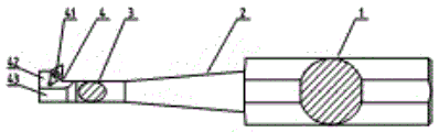
fig. 1 shows a schematic view of a hub axle hole reverse boring tool provided by an embodiment of the present invention;
FIG. 2 is a schematic view of FIG. 1 during reverse boring of a bore in a hub bearing;
reference numerals:
wherein, the corresponding relation between the reference numbers and the part names in fig. 1 is:
1 clamping part, 2 conical part, 3 cylindrical part, 4 end part, 41 blade mounting groove, 42 first plane and 43 second plane.
Detailed Description
In order to make the aforementioned objects, features and advantages of the present invention more clearly understood, the present invention will be described in further detail with reference to the accompanying drawings and detailed description. It should be noted that the embodiments and features of the embodiments of the present application may be combined with each other without conflict.
In the following description, numerous specific details are set forth in order to provide a thorough understanding of the present invention, however, the present invention may be practiced in other ways than those specifically described herein, and therefore the scope of the present invention is not limited by the specific embodiments disclosed below.
As shown in fig. 1 and 2, an object of the present invention is to provide a hub axle hole reverse boring tool, which includes a clamping portion 1, a tapered portion 2, a cylindrical portion 3 and an end portion 4, wherein an end surface of the clamping portion 1 is connected to a bottom end surface of the tapered portion 2, a top end surface of the tapered portion 2 is connected to one end of the cylindrical portion 3, the other end of the cylindrical portion 3 is connected to the end portion 4, and a blade mounting groove 41 is formed in the end portion 4.
The utility model provides a wheel hub shaft hole reverse boring cutter, use toper portion 2 to increase the length of cutter, improve the structural strength of cutter, reduce because of the longer cutter problem that shakes of taking place in the course of working of cutter, improve the machining precision, can stretch into in darker or less shaft hole through cylindricality portion 3, carry out reverse bore hole processing to the shaft hole internal face of keeping away from the cutter end in shaft hole, the both ends in the shaft hole of the product after making the processing keep same coordinate system, be particularly useful for motorcycle or electric motor car wheel hub's dead eye processing, avoid because the dead eye of having processed one end earlier, take place coordinate and positioning deviation when reprocessing the dead eye of the other end after reverse installation location again, eliminate the axiality deviation of dead eye by a wide margin, improve the product machining precision, improve the product percent of pass.
According to the utility model discloses foretell wheel hub shaft hole reverse boring cutter can also have following additional technical characterstic:
in the above technical solution, preferably, the axial cross section of the tapered portion 2 is elliptical.
In the above embodiment, the major axis direction of the elliptical conical portion 2 has greater mechanical structural strength than the minor axis direction, so the elliptical major axis direction of the conical portion 2 can be used as the feeding direction of the cutter, so that the cutter can bear larger force in the feeding process, the stability of the cutter is improved, and the elliptical minor axis direction of the conical portion 2 is favorable for reducing the volume of the cutter, reducing the weight of the cutter, and improving the capability of the cutter passing through the aperture.
In the above technical solution, preferably, the axial cross section of the cylindrical portion 3 is an ellipse, and one end surface of the cylindrical portion 3 is a tip end surface of the tapered portion 2.
In the above embodiment, because the long axis direction of the elliptical cylindrical portion 3 has greater mechanical strength than the short axis direction, the elliptical long axis direction of the cylindrical portion 3 can be used as the feeding direction of the tool, and the top end face of the tapered portion 2 is used as the reference of the cylindrical portion 3, so that the tool can bear larger force during feeding, thereby improving the stability of the tool, and the elliptical short axis direction of the cylindrical portion 3 is beneficial to reducing the volume of the tool, reducing the weight of the tool, and improving the capability of the tool to pass through the hole diameter.
In the above technical solution, preferably, the end portion 4 is provided with a first plane 42 and a second plane 43, the first plane 42 is provided with an L-shaped protrusion, the blade mounting groove 41 is arranged at an included angle of the protrusion, the blade mounting groove 41 is provided with a threaded hole for mounting a blade, the second plane 43 is higher than the first plane 42, the second plane 43 is connected with the cylindrical portion 3 by an arc-shaped tangent plane, and the first plane 42 is in smooth transition with the arc-shaped tangent plane.
In the above embodiment, the first plane 42 is the plane where the blade mounting groove 41 is located, the first plane 42 is provided with the L-shaped protruding portion, the range of the processing aperture of the blade can be increased, the force stability of the cutter is improved, the blade mounting groove 41 is arranged at the included angle of the protruding portion, the inner side edge of the cutter and the outer side surface of the cylindrical portion 3 form an angle smaller than 90 degrees, the second plane 43 is connected with the cylindrical portion 3 through an arc section, the first plane 42 and the arc section are in smooth transition, mainly to reduce the volume and weight of the end portion 4, the aperture passing capability of the end portion 4 and the cutter is improved, and the aperture discharging capability of cutting chips is facilitated.
The above is only a preferred embodiment of the present invention, and is not intended to limit the present invention, and various modifications and changes will occur to those skilled in the art. Any modification, equivalent replacement, or improvement made within the spirit and principle of the present invention should be included in the protection scope of the present invention.
Claims (4)
1. The utility model provides a wheel hub shaft hole reverse boring cutter, includes clamping part (1), toper portion (2), cylindricality portion (3) and tip (4), its characterized in that, an end face of clamping part (1) with the bottom end face of toper portion (2) links to each other, the top end face of toper portion (2) with the one end of cylindricality portion (3) links to each other, the other end of cylindricality portion (3) with tip (4) link to each other, be equipped with blade mounting groove (41) on tip (4).
2. The hub shaft hole reverse boring tool according to claim 1, characterized in that the axial cross section of the tapered portion (2) is elliptical.
3. The hub shaft hole reverse boring tool according to claim 2, wherein the cylindrical portion (3) is elliptical in axial cross section, and one end surface of the cylindrical portion (3) is a tip end surface of the tapered portion (2).
4. The hub shaft hole reverse boring tool according to claim 3, characterized in that the end portion (4) is provided with a first plane (42) and a second plane (43), the first plane (42) is provided with an L-shaped protruding portion, the blade mounting groove (41) is arranged at a corner of the protruding portion, the blade mounting groove (41) is provided with a threaded hole for mounting a blade, the second plane (43) is higher than the first plane (42), the second plane (43) is connected with the cylindrical portion (3) through a circular arc tangent plane, and the first plane (42) is in smooth transition with the circular arc tangent plane.
Priority Applications (1)
| Application Number | Priority Date | Filing Date | Title |
|---|---|---|---|
| CN201922050860.7U CN211489677U (en) | 2019-11-25 | 2019-11-25 | Reverse boring cutter for hub shaft hole |
Applications Claiming Priority (1)
| Application Number | Priority Date | Filing Date | Title |
|---|---|---|---|
| CN201922050860.7U CN211489677U (en) | 2019-11-25 | 2019-11-25 | Reverse boring cutter for hub shaft hole |
Publications (1)
| Publication Number | Publication Date |
|---|---|
| CN211489677U true CN211489677U (en) | 2020-09-15 |
Family
ID=72411286
Family Applications (1)
| Application Number | Title | Priority Date | Filing Date |
|---|---|---|---|
| CN201922050860.7U Active CN211489677U (en) | 2019-11-25 | 2019-11-25 | Reverse boring cutter for hub shaft hole |
Country Status (1)
| Country | Link |
|---|---|
| CN (1) | CN211489677U (en) |
Cited By (1)
| Publication number | Priority date | Publication date | Assignee | Title |
|---|---|---|---|---|
| CN112427665A (en) * | 2020-11-09 | 2021-03-02 | 上海中船三井造船柴油机有限公司 | Back boring tool for cylinder block Glan hole and machining method |
-
2019
- 2019-11-25 CN CN201922050860.7U patent/CN211489677U/en active Active
Cited By (1)
| Publication number | Priority date | Publication date | Assignee | Title |
|---|---|---|---|---|
| CN112427665A (en) * | 2020-11-09 | 2021-03-02 | 上海中船三井造船柴油机有限公司 | Back boring tool for cylinder block Glan hole and machining method |
Similar Documents
| Publication | Publication Date | Title |
|---|---|---|
| CN205173237U (en) | Cylindrical roller bearing | |
| CN106351962B (en) | A kind of bearing block structure and its processing technology | |
| CN210817518U (en) | Back-pull type three-jaw chuck | |
| CN208840981U (en) | A kind of eccentric shaft gripper | |
| CN204817674U (en) | A spinning wheel for gas cylinder production | |
| CN201432138Y (en) | Integral Gradient Core Diameter Ball End Mills | |
| CN202833596U (en) | Forged piece of crankshaft | |
| CN204997099U (en) | High -speed handle of a knife of high elasticity cone | |
| CN219464963U (en) | Arc product deburring cutter | |
| CN204094219U (en) | A kind of compound tool | |
| CN211127331U (en) | Improve stator core structure of oil spout cooling motor cooling effect | |
| CN112872518A (en) | Electrode for machining hexagonal bolt cold forming die | |
| CN204724949U (en) | A kind of engine cylinder cover oil injector hole combination cutter | |
| CN104923602B (en) | Interior six side's flower-shape groove securing member forming method and moulds | |
| CN204603335U (en) | A kind of gang tool of external splines nylon coated layer processing | |
| CN204893535U (en) | Main shaft pine sword device | |
| CN216430339U (en) | Braking ring blank | |
| CN220591592U (en) | Turning blade structure | |
| CN211304632U (en) | Stamping die | |
| CN217412082U (en) | Rim roll forming machine main shaft | |
| CN105689743A (en) | Telescopic boring rod | |
| CN219130805U (en) | A integrative cover sword of shaping for differential mechanism casing | |
| CN217529315U (en) | Combustion chamber top surface countersink forming cutter | |
| CN217142585U (en) | Tooth turning cutter without front angle, rear angle and unequal outer ring and tooth removing | |
| CN202622433U (en) | Fine engraving machine main shaft lengthening rod |
Legal Events
| Date | Code | Title | Description |
|---|---|---|---|
| GR01 | Patent grant | ||
| GR01 | Patent grant | ||
| TR01 | Transfer of patent right |
Effective date of registration: 20210608 Address after: Situn village, situn community, Shengjing street, Fuyuan County, Qujing City, Yunnan Province Patentee after: Yunnan Jinfei motorcycle accessories manufacturing Co.,Ltd. Address before: 321000 No.1 jinyidong expressway, Jindong Economic Development Zone, Jinhua City, Zhejiang Province Patentee before: ZHEJIANG JINFEI MOTORCYCLE WHEEL Co.,Ltd. |
|
| TR01 | Transfer of patent right |