CN211468020U - Sand table model numerical control engraving machine with cleaning function - Google Patents
Sand table model numerical control engraving machine with cleaning function Download PDFInfo
- Publication number
- CN211468020U CN211468020U CN201921867485.9U CN201921867485U CN211468020U CN 211468020 U CN211468020 U CN 211468020U CN 201921867485 U CN201921867485 U CN 201921867485U CN 211468020 U CN211468020 U CN 211468020U
- Authority
- CN
- China
- Prior art keywords
- dust
- installation frame
- engraving machine
- numerical control
- sand table
- Prior art date
- Legal status (The legal status is an assumption and is not a legal conclusion. Google has not performed a legal analysis and makes no representation as to the accuracy of the status listed.)
- Expired - Fee Related
Links
- 239000004576 sand Substances 0.000 title claims abstract description 18
- 238000004140 cleaning Methods 0.000 title claims abstract description 15
- 239000000428 dust Substances 0.000 claims abstract description 65
- 238000009434 installation Methods 0.000 claims abstract description 38
- 238000007789 sealing Methods 0.000 claims description 6
- 230000001737 promoting effect Effects 0.000 abstract description 3
- 230000000694 effects Effects 0.000 description 3
- 230000007613 environmental effect Effects 0.000 description 3
- 238000010521 absorption reaction Methods 0.000 description 2
- 230000003044 adaptive effect Effects 0.000 description 1
- 230000004075 alteration Effects 0.000 description 1
- 230000009286 beneficial effect Effects 0.000 description 1
- 230000003749 cleanliness Effects 0.000 description 1
- 238000000034 method Methods 0.000 description 1
- 238000012986 modification Methods 0.000 description 1
- 230000004048 modification Effects 0.000 description 1
- 238000006467 substitution reaction Methods 0.000 description 1
- 238000003466 welding Methods 0.000 description 1
Images


Landscapes
- Auxiliary Devices For Machine Tools (AREA)
Abstract
The utility model discloses a sand table model numerical control engraving machine with cleaning function, which belongs to the field of sand table model numerical control engraving machines and comprises a workbench, wherein a rack is arranged on the workbench, the engraving machine is arranged on the rack, a placing plate is arranged on the workbench, an installation frame is fixed on the workbench, the installation frame is of an inverted U-shaped structure, through holes are respectively formed in two side walls of the installation frame, guide rods are movably arranged in the through holes, one end of each guide rod is fixedly provided with an installation rod arranged horizontally, hairbrushes are respectively arranged on the side walls, which are close to the two installation rods, threaded holes are respectively formed in the two side walls of the installation frame, the threaded holes are positioned between the two through holes, and a screw rod is connected in; the utility model relates to a novelty, can be automatic clean the sand table model after the sculpture, improve work efficiency, alleviate work burden, and can collect the dust after the cleanness, avoid the polluted environment, convenient operation is worth promoting.
Description
Technical Field
The utility model belongs to the technical field of sand table model numerical control engraver, concretely relates to sand table model numerical control engraver with clean function.
Background
When a sand table model is manufactured, a numerical control engraving machine is needed, however, more dust is left on the surface of an engraved workpiece, the workpiece needs to be cleaned in order to keep cleanliness, the existing workpiece cleaning after engraving is generally completed through manual operation, the working efficiency is low, and the workload of workers is increased.
SUMMERY OF THE UTILITY MODEL
An object of the utility model is to provide a sand table model numerical control engraver with clean function to solve the problem that proposes among the above-mentioned background art.
In order to achieve the above object, the utility model provides a following technical scheme: a sand table model numerical control engraving machine with a cleaning function comprises a workbench, wherein a rack is installed on the workbench, an engraving machine is installed on the rack, a placing plate is arranged on the workbench, an installation frame is fixed on the workbench and is of an inverted U-shaped structure, through holes are formed in two side walls of the installation frame, guide rods are movably arranged in the through holes, one end of each guide rod is fixed with an installation rod which is horizontally arranged, hairbrushes are installed on the side walls, close to the two installation rods, of the two side walls of the installation frame, threaded holes are formed in the two side walls of the installation frame, the threaded holes are located between the two through holes, a screw rod is connected with the threaded holes in a threaded manner, one end of the screw rod is rotatably installed on the installation rod, a dust suction hole is formed in the top wall of the installation frame, the dust suction hole is of a circular structure, a grid plate, the top of installation frame is fixed with the dust collection box, the welding has the fixed plate on the lateral wall of installation frame, install the draught fan on the fixed plate, the air intake connection of draught fan has pipeline two, and the one end of pipeline two is connected on the dust collection box, the dust collection box is provided with open cuboid structure for the top, the bottom of dust collection box is provided with the collecting box, the connecting rod has all been welded to the both sides at collecting box top, the top of two connecting rods is fixed with the roof that same level set up, install the handle on the roof.
Adopt above-mentioned scheme, according to the size of sculpture work piece, rotate the screw rod, the screw rod removes in the screw hole, thereby the distance between the adjustment installation pole, make the brush adapt to the size of work piece, the guide arm plays spacing guide's effect, avoid the installation pole to rotate along with the rotation of screw rod, will treat that the glyptic work piece is placed on placing the board, utilize the engraver to accomplish the back to the work piece sculpture, utilize the conveyer belt to drive glyptic work piece and remove, open the draught fan, when the work piece removes in the installation frame, the brush is clean with the dust on workpiece surface, and wind-force through the draught fan, inhale the dust collection box with the dust, avoid the dust to fly upward, the environmental protection, and do not need artifical cleanness, great improvement work efficiency, reduce staff's work burden, be worth.
In a preferred embodiment, a conveyor belt is provided on the table, and the placement plate is fixed to the conveyor belt.
By adopting the scheme, the conveying belt is arranged on the workbench, so that workpieces can be automatically conveyed, the automation degree is high, and the cleaning efficiency is improved.
In a preferred embodiment, the placing plate is provided with a placing groove, and the placing plate is positioned right below the engraving machine.
By adopting the scheme, the placing groove is formed in the placing plate, the stability of placing the workpiece can be improved, the shape of the placing groove can be adjusted according to the actual shape of the workpiece, and the applicability is high.
In a preferred embodiment, the dust hood is a conical structure with a small top and a big bottom, and the bottom end of the dust hood is matched with the size of the dust collection hole.
By adopting the scheme, the dust hood with the conical structure with the small upper part and the large lower part has the advantages of large dust absorption area and good dust absorption effect, and can prevent dust from flying around after cleaning and protect the environment.
In a preferred embodiment, the cross-sectional area of the top plate is matched with the size of the cross-sectional area of the inner cavity of the dust box, and a sealing strip is bonded on the side wall of the top plate.
By adopting the scheme, the top plate is matched with the dust collection box in size, and the sealing strip is arranged on the side wall of the top plate, so that the sealing property between the top plate and the dust collection box is ensured.
Compared with the prior art, the beneficial effects of the utility model are that:
according to the sand table model numerical control engraving machine with the cleaning function, the positions of the hairbrushes can be adjusted by arranging the mounting frame, the hairbrushes, the guide rods, the mounting rods, the screw rods and other structures, so that the numerical control engraving machine is suitable for workpieces with different sizes, dust on the surfaces of the workpieces is effectively cleared, manual operation is not needed, and the working strength is reduced;
this sand table model numerical control engraver with clean function is through setting up structures such as suction hood, pipeline one, dust collection box, draught fan, collecting box, roof and connecting rod, and the dust after the collection is clear that can be convenient avoids the dust to fly upward, and the environmental protection is worth promoting.
Drawings
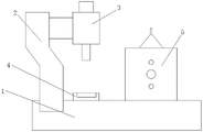
Fig. 1 is a schematic structural view of the present invention;
fig. 2 is a side view of the mounting frame of the present invention;
fig. 3 is a schematic structural view of the dust box of the present invention.
In the figure: 1. a work table; 2. a frame; 3. an engraving machine; 4. placing the plate; 5. a mounting frame; 6. a guide bar; 7. mounting a rod; 8. a brush; 9. a screw; 10. a grid plate; 11. a dust hood; 12. a dust collection box; 13. A first pipeline; 14. a fixing plate; 15. an induced draft fan; 16. a second pipeline; 17. a collection box; 18. a connecting rod; 19. a top plate; 20. a handle.
Detailed Description
The present invention will be further described with reference to the following examples.
The following examples are intended to illustrate the invention, but are not intended to limit the scope of the invention. The condition in the embodiment can be further adjusted according to concrete condition the utility model discloses a it is right under the design prerequisite the utility model discloses a simple improvement of method all belongs to the utility model discloses the scope of claiming.
Referring to fig. 1-3, the utility model provides a sand table model numerical control engraving machine with cleaning function, which comprises a workbench 1, wherein a frame 2 is arranged on the workbench 1, an engraving machine 3 is arranged on the frame 2, a placing plate 4 is arranged on the workbench 1, a conveying belt is arranged on the workbench 1, and the placing plate 4 is fixed on the conveying belt (see fig. 1); the conveying belt is arranged on the workbench 1, workpieces can be automatically conveyed, the automation degree is high, and the cleaning efficiency is improved.
An installation frame 5 is fixed on the workbench 1, the installation frame 5 is of an inverted U-shaped structure, through holes are formed in two side walls of the installation frame 5, a placing groove is formed in a placing plate 4, and the placing plate 4 is located right below the engraving machine 3 (see fig. 1); the placing groove is formed in the placing plate 4, so that the placing stability of the workpiece can be improved, the shape of the placing groove can be adjusted according to the actual shape of the workpiece, and the applicability is high.
Guide rods 6 are movably arranged in the through holes, one end of each guide rod 6 is fixedly provided with a same horizontally arranged installation rod 7, side walls, close to the two installation rods 7, are respectively provided with a hairbrush 8, two side walls of the installation frame 5 are respectively provided with a threaded hole, the threaded holes are positioned between the two through holes, a screw rod 9 is connected in the threaded holes, one end of the screw rod 9 is rotatably arranged on the installation rod 7, the top wall of the installation frame 5 is provided with a dust suction hole, the dust suction hole is of a circular structure, a grid plate 10 is fixed at the bottom end of the dust suction hole, a dust suction cover 11 is arranged above the grid plate 10, the dust suction cover 11 is of a conical structure with a small upper part and a large lower part, and; the dust hood 11 with the conical structure with the small upper part and the big lower part has the advantages of large dust collection area and good dust collection effect, and can prevent the dust from flying around after cleaning and protect the environment.
The top end of the dust hood 11 is connected with a first pipeline 13, the top end of the installation frame 5 is fixed with a dust collection box 12, a fixing plate 14 is welded on one side wall of the installation frame 5, an induced draft fan 15 is installed on the fixing plate 14, an air inlet of the induced draft fan 15 is connected with a second pipeline 16, one end of the second pipeline 16 is connected to the dust collection box 12, the dust collection box 12 is of a cuboid structure with an opening in the top, a collection box 17 is arranged at the bottom of the dust collection box 12, connecting rods 18 are welded on two sides of the top of the collection box 17, top ends of the two connecting rods 18 are fixed with top plates 19 which are arranged horizontally, handles 20 are installed on the top plates 19, the cross sectional area of the top plates 19 is matched with the cross sectional area size of; the top plate 19 is matched with the dust box 12 in size, and the side wall of the top plate 19 is provided with a sealing strip, so that the sealing property between the top plate 19 and the dust box 12 is ensured.
When in use, the screw rod 9 is rotated according to the size of the carving workpiece, the screw rod 9 moves in the threaded hole, so that the distance between the mounting rods 7 is adjusted, the hairbrush 8 is adaptive to the size of the workpiece, the guide rod 6 plays a role of limiting and guiding, the mounting rods 7 are prevented from rotating along with the rotation of the screw rod 9, the workpiece to be carved is placed on the placing plate 4, the placing plate 4 is provided with a placing groove, so that the workpiece can be stably placed, after the carving of the workpiece is completed by the carving machine 3, the carved workpiece is driven by the conveying belt to move, the induced draft fan 15 is opened, when the workpiece moves into the mounting frame 5, the hairbrush 8 cleans dust on the surface of the workpiece, the dust is sucked into the dust collection box 12 through the dust hood 11 and the pipeline one 13 by the wind power of the induced draft fan 15, the dust enters the dust collection box 12 due to sudden increase of area, and, avoid the dust to fly upward, the environmental protection, and do not need artifical clean, great improvement work efficiency, reduce staff's work burden, be worth promoting, need handle the dust of collection and make, pulling handle 20 takes out the interface with collecting box 17 from dust collection box 12, convenient operation.
Although embodiments of the present invention have been shown and described, it will be appreciated by those skilled in the art that changes, modifications, substitutions and alterations can be made in these embodiments without departing from the principles and spirit of the invention, the scope of which is defined in the appended claims and their equivalents.
Claims (5)
1. The utility model provides a sand table model numerical control engraver with clean function, includes workstation (1), its characterized in that: the working table is characterized in that a rack (2) is installed on the working table (1), an engraving machine (3) is installed on the rack (2), a placing plate (4) is arranged on the working table (1), an installation frame (5) is fixed on the working table (1), the installation frame (5) is of an inverted U-shaped structure, through holes are formed in two side walls of the installation frame (5), guide rods (6) are movably arranged in the through holes, one end of each of the two guide rods (6) is fixedly provided with an installation rod (7) which is arranged horizontally, brush brushes (8) are installed on the side walls, close to the two installation rods (7), threaded holes are formed in the two side walls of the installation frame (5), the threaded holes are located between the two through holes, a screw rod (9) is connected to the threaded holes in a threaded manner, one end of the screw rod (9) is rotatably installed on the installation rod (7, a grid plate (10) is fixed at the bottom end of the dust suction hole, a dust hood (11) is installed above the grid plate (10), a first pipeline (13) is connected to the top end of the dust hood (11), a dust collection box (12) is fixed to the top end of the installation frame (5), a fixing plate (14) is welded on one side wall of the installation frame (5), an induced draft fan (15) is installed on the fixing plate (14), a second pipeline (16) is connected to an air inlet of the induced draft fan (15), one end of the second pipeline (16) is connected to the dust collection box (12), the top of the dust collection box (12) is provided with an open cuboid structure, the bottom of the dust collection box (12) is provided with a collection box (17), connecting rods (18) are welded to the two sides of the top of the collection box (17), top ends of the two connecting rods (18) are fixed with top plates (19) which are arranged horizontally, and handles (20) are mounted on the top plates (19).
2. The sand table model numerical control engraving machine with the cleaning function as claimed in claim 1, characterized in that: the workbench (1) is provided with a conveying belt, and the placing plate (4) is fixed on the conveying belt.
3. The sand table model numerical control engraving machine with the cleaning function as claimed in claim 1, characterized in that: the placing plate (4) is provided with a placing groove, and the placing plate (4) is positioned under the engraving machine (3).
4. The sand table model numerical control engraving machine with the cleaning function as claimed in claim 1, characterized in that: the dust hood (11) is of a conical structure with a small upper part and a large lower part, and the bottom end of the dust hood (11) is matched with the size of the dust collection hole.
5. The sand table model numerical control engraving machine with the cleaning function as claimed in claim 1, characterized in that: the cross sectional area of the top plate (19) is matched with the size of the cross sectional area of the inner cavity of the dust collection box (12), and a sealing strip is bonded on the side wall of the top plate (19).
Priority Applications (1)
| Application Number | Priority Date | Filing Date | Title |
|---|---|---|---|
| CN201921867485.9U CN211468020U (en) | 2019-11-01 | 2019-11-01 | Sand table model numerical control engraving machine with cleaning function |
Applications Claiming Priority (1)
| Application Number | Priority Date | Filing Date | Title |
|---|---|---|---|
| CN201921867485.9U CN211468020U (en) | 2019-11-01 | 2019-11-01 | Sand table model numerical control engraving machine with cleaning function |
Publications (1)
| Publication Number | Publication Date |
|---|---|
| CN211468020U true CN211468020U (en) | 2020-09-11 |
Family
ID=72365395
Family Applications (1)
| Application Number | Title | Priority Date | Filing Date |
|---|---|---|---|
| CN201921867485.9U Expired - Fee Related CN211468020U (en) | 2019-11-01 | 2019-11-01 | Sand table model numerical control engraving machine with cleaning function |
Country Status (1)
| Country | Link |
|---|---|
| CN (1) | CN211468020U (en) |
-
2019
- 2019-11-01 CN CN201921867485.9U patent/CN211468020U/en not_active Expired - Fee Related
Similar Documents
| Publication | Publication Date | Title |
|---|---|---|
| CN211052658U (en) | Planer type milling machine workbench | |
| CN215965041U (en) | Solar panel belt cleaning device for solar energy power generation | |
| CN207155009U (en) | A kind of laser cutting machine tool high effect dust cleaner | |
| CN214441133U (en) | A board cleaning device | |
| CN218394866U (en) | Adjustable automatic tool for sweeping welding powder | |
| CN210476182U (en) | Milling machine workbench for milling notebook computer jig | |
| CN210474754U (en) | Dust collecting equipment for power equipment | |
| CN211219872U (en) | Dust collector is used in milling machine processing | |
| CN221020056U (en) | Workbench cleaning device for part machining | |
| CN119282257A (en) | Automatic deburring device and deburring method | |
| CN211493477U (en) | Dust suction device of wood carving machine | |
| CN218050625U (en) | Scrap collecting device of band sawing machine | |
| CN214725003U (en) | Saw-dust cleaning device is used in fitment design construction | |
| CN213255788U (en) | Automatic dust extraction of household paper processing equipment | |
| CN211639208U (en) | Ash handling equipment for milling machine | |
| CN210452004U (en) | Chip removal device of numerical control machine tool | |
| CN214489843U (en) | Carving mills machine with dust extraction | |
| CN210450201U (en) | Glass bottle self-cleaning device | |
| CN216705194U (en) | Industrial dish cabinet is with automatic robot that cleans | |
| CN222175210U (en) | Cleaning device for injection molded parts | |
| CN219745622U (en) | High-toughness corrosion-resistant hollow brick ash removal device | |
| CN205464575U (en) | Board edge cutter of automatic dust fall can spray | |
| CN216125855U (en) | Efficient electrostatic precipitator ash removal device | |
| CN117774040B (en) | PVT photovoltaic photo-thermal plate cutting integrated equipment | |
| CN211104336U (en) | Chip removal device of electric tool |
Legal Events
| Date | Code | Title | Description |
|---|---|---|---|
| GR01 | Patent grant | ||
| GR01 | Patent grant | ||
| CF01 | Termination of patent right due to non-payment of annual fee |
Granted publication date: 20200911 |
|
| CF01 | Termination of patent right due to non-payment of annual fee |