CN211456516U - Electrified wire feeding and discharging device of high-voltage overhead bare conductor insulation rubber coating robot - Google Patents
Electrified wire feeding and discharging device of high-voltage overhead bare conductor insulation rubber coating robot Download PDFInfo
- Publication number
- CN211456516U CN211456516U CN202020396243.2U CN202020396243U CN211456516U CN 211456516 U CN211456516 U CN 211456516U CN 202020396243 U CN202020396243 U CN 202020396243U CN 211456516 U CN211456516 U CN 211456516U
- Authority
- CN
- China
- Prior art keywords
- robot
- conductor insulation
- rubber coating
- bare conductor
- cable
- Prior art date
- Legal status (The legal status is an assumption and is not a legal conclusion. Google has not performed a legal analysis and makes no representation as to the accuracy of the status listed.)
- Active
Links
Images
Abstract
The utility model belongs to the technical field of automatic change robot, a electrified winding displacement device that goes up of high-pressure built on stilts bare conductor insulation rubber coating robot is related to, including frame construction's equipment platform, install at the spooler at equipment platform bottom both ends and with the stores pylon that equipment platform cooperation was used, install the reduction gear in the pivot of spooler, stores pylon both ends fixed mounting has the couple of being convenient for hang the stores pylon on the cable, the lifting rope that the lower part free end fixedly connected with of couple was worn out from the spooler, this electrified winding displacement device that goes up of rubber coating robot, realize conveniently hanging on the lift high altitude cable, and can form load-bearing platform on the high altitude cable, make things convenient for rubber coating equipment in high altitude cable operation.
Description
Technical Field
The utility model belongs to the technical field of automatic change robot, a high-pressure built on stilts bare conductor insulation rubber coating robot is electrified to be traditional thread binding putting from top to bottom.
Background
The injection coating insulation layer robot is mainly applied to insulation treatment of bare conductors of power distribution overhead lines, and a power distribution network refers to a power supply network with the voltage level of 10 kV-400V. At present, the urban distribution network is basically insulated, more than 50% of rural distribution networks are bare conductors, and when the distribution lines are frequently tripped in wind and rain, the power supply benefit and the high-quality service are influenced.
In the cable overhead operation in the prior art, for example, the cable insulating layer coating in the cable stringing process, and the operations on the cable stringing construction and the subsequent maintenance line, including the overhead branch cutting and cleaning operations around the line, the cleaning operations of sundries such as kites and the like on the power line, all need to travel along the cable line and perform construction and operation treatment, at present, the operations are usually performed on the cable by manually hanging, which is dangerous to operators, and the construction efficiency is very low, especially the subsequent maintenance line needs to be shut down to perform the operations, thereby affecting the normal use of the cable.
Because the high-voltage cable has a certain hoisting bearing capacity, a constructor is usually directly hoisted on the corresponding cable to work. The prior art also has the operation realization scheme of a corresponding cutting robot and the like, but the corresponding operation equipment is usually required to be hoisted to a cable from a cable tower, and the equipment is usually heavy and inconvenient to operate in the air, so that the equipment or personnel are easy to fall. In addition, the hoisted equipment is difficult to advance on the cable, so that the spraying robot and the daily maintenance are difficult to operate, and the market acceptance is low.
SUMMERY OF THE UTILITY MODEL
In view of this, the utility model discloses a solve the current high altitude cable operation equipment and go up and down and the inconvenient problem of work operation, provide a high-pressure built on stilts bare conductor insulation rubber coating robot and go up and down traditional thread binding putting on the electric belt, realize conveniently hoisting to the high altitude cable on to can form load-bearing platform, make things convenient for the high altitude cable operation on the high altitude cable.
In order to achieve the purpose, the utility model provides an electrified winding displacement device that goes up of insulating rubber coating robot of high-tension aerial bare conductor, including frame construction's equipment platform, install at the spooler at equipment platform bottom both ends and with the stores pylon that equipment platform cooperation was used, install the reduction gear in the pivot of spooler, stores pylon both ends fixed mounting has the couple of being convenient for hang the stores pylon on the cable, the lifting rope that the lower part free end fixedly connected with of couple was worn out from the spooler.
The beneficial effect of this basic scheme lies in: frame construction's equipment platform is used for placing rubber coating robot, and the spooler is used for accomodating the used lifting rope of rubber coating robot line from top to bottom, and the stores pylon is used for using with equipment platform cooperation, and the stores pylon both ends are the couple of similar key ring, and the lower extreme and the lifting rope fixed connection of couple can directly hang on the cable through the rack area lower part equipment platform.
Further, an insulating buffer is arranged between the hook and the lifting rope. Has the advantages that: the insulating buffer between the hook and the lifting rope plays a role in buffering the lifting rope, the equipment platform and the swing of the rubber coating robot on the equipment platform.
Further, the cable guide profile comprises a plurality of cable guide profiles fixedly mounted on the hung equipment. Has the advantages that: the cable guide profile serves to guide the cable into the hook.
Furthermore, two ends of the equipment platform are respectively and fixedly provided with a triangular support, and the top of the triangular support is fixedly provided with a threading hole for the lifting rope to penetrate out conveniently. Has the advantages that: the threading hole on the A-frame plays the spacing effect of wearing out the lifting rope from the spooler, reduces the swing of rubber coating robot on lifting rope, equipment platform and the equipment platform, maintains equipment balance.
Furthermore, an inner groove for winding the lifting rope is arranged on the wire rewinding device. Has the advantages that: the internal groove on the wire rewinding device is convenient for clamping the lifting rope, and the winding firmness of the lifting rope is improved.
Furthermore, a clutch is arranged between the wire rewinding device and the speed reducer. Has the advantages that: when the lifting rope is hung on the equipment platform, the lifting rope is manually taken out, and the clutch between the wire rewinding device and the speed reducer can ensure that the lifting rope is manually pulled out without being influenced by the speed reducer.
Further, the speed reducer is a worm gear speed reducer. Has the advantages that: in order to ensure the anti-falling safety of the equipment, the speed reducer is a worm gear speed reducer, and the self-locking performance of the worm gear speed reducer can prevent the hanging rack from falling.
The beneficial effects of the utility model reside in that:
the utility model discloses an electrified winding displacement device that goes up of high-tension aerial bare conductor insulation rubber coating robot sets up cable guide profile at the stores pylon middle part, and the stores pylon both ends set up the couple of key ring form, and cable guide profile can be hung the winding displacement device on the cable in advance that stores pylon, equipment platform formed, and the couple that has self-locking function realizes that stores pylon, equipment platform form the accuracy of winding displacement device hangs to this kind of couple that has self-locking function can not appear cable unhook phenomenon. The insulating buffer at the lower end of the hook plays a role in preventing the lifting rope, the equipment platform and the rubber coating robot on the equipment platform from swinging. The lifting of the equipment platform can be controlled through the speed reducer, the equipment platform for placing the rubber coating robot is lifted to a proper position, and the safety and the convenience of lifting the ground operation equipment platform are realized.
Additional advantages, objects, and features of the invention will be set forth in part in the description which follows and in part will become apparent to those having ordinary skill in the art upon examination of the following or may be learned from practice of the invention. The objectives and other advantages of the invention may be realized and attained by the means of the instrumentalities and/or combinations particularly pointed out in the appended claims.
Drawings
For the purposes of promoting a better understanding of the objects, features and advantages of the invention, reference will now be made to the following detailed description taken in conjunction with the accompanying drawings in which:
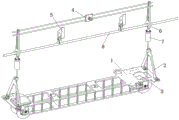
fig. 1 is the utility model discloses the electrified structure schematic diagram who goes up the pay-off of high-voltage aerial bare conductor insulation rubber coating robot.
Reference numerals: the device comprises a device platform 1, a triangular support 2, a wire rewinding device 3, a hanging frame 4, a cable guide outline 5, a hook 6, an insulating buffer 7 and a cable 8.
Detailed Description
The following description of the embodiments of the present invention is provided for illustrative purposes, and other advantages and effects of the present invention will be readily apparent to those skilled in the art from the disclosure herein. The present invention can also be implemented or applied through other different specific embodiments, and various details in the present specification can be modified or changed based on different viewpoints and applications without departing from the spirit of the present invention. It should be noted that the drawings provided in the following embodiments are only for illustrating the basic idea of the present invention, and the features in the following embodiments and examples may be combined with each other without conflict.
Wherein the showings are for the purpose of illustrating the invention only and not for the purpose of limiting the same, and in which there is shown by way of illustration only and not in any way limiting the scope of the invention; for a better understanding of the embodiments of the present invention, some parts of the drawings may be omitted, enlarged or reduced, and do not represent the size of an actual product; it will be understood by those skilled in the art that certain well-known structures in the drawings and descriptions thereof may be omitted.
The same or similar reference numerals in the drawings of the embodiments of the present invention correspond to the same or similar parts; in the description of the present invention, it should be understood that if there are terms such as "upper", "lower", "left", "right", "front", "back", etc., indicating directions or positional relationships based on the directions or positional relationships shown in the drawings, it is only for convenience of description and simplification of description, but it is not intended to indicate or imply that the device or element referred to must have a specific direction, be constructed and operated in a specific direction, and therefore, the terms describing the positional relationships in the drawings are only used for illustrative purposes and are not to be construed as limiting the present invention, and those skilled in the art can understand the specific meanings of the terms according to specific situations.
As shown in fig. 1, the high-voltage overhead bare conductor insulation encapsulation robot live-line wiring and winding device comprises an equipment platform 1 with a frame structure, a wire rewinding device 3 arranged at two ends of the bottom of the equipment platform 1, and a hanging rack 4 matched with the equipment platform 1 for use, wherein the equipment platform 1 is a platform formed by a plurality of parallel plates. The frame-structured equipment platform 1 also facilitates the threading out of the lifting rope. Frame construction's equipment platform 1 is used for placing the rubber coating robot, and spooler 3 is used for accomodating the used lifting rope of rubber coating robot upper and lower line, and stores pylon 4 is used for using with equipment platform 1 cooperation.
The two ends of the equipment platform 1 are respectively and fixedly provided with a triangular support 2, and the top of the triangular support 2 is fixedly provided with a threading hole for the lifting rope to penetrate out conveniently. The threading hole on the A-frame 2 plays the spacing effect of the lifting rope of wearing out from the spooler 3, reduces the swing of rubber coating robot on lifting rope, equipment platform 1 and the equipment platform 1, maintains equipment balance.
The wire-rewinding device 3 is provided with an inner groove for winding the lifting rope. The internal groove on the wire rewinding device 3 is convenient for clamping the lifting rope, and the winding firmness of the lifting rope is improved. A speed reducer is arranged on a rotating shaft of the wire rewinding device 3, and a clutch is arranged between the wire rewinding device 3 and the speed reducer. When the lifting rope is hung on the equipment platform 1, the lifting rope is manually taken out, and the clutch between the wire rewinding device 3 and the speed reducer can ensure that the lifting rope is manually pulled out without being influenced by the speed reducer. The reducer is a worm gear reducer. In order to ensure the anti-falling safety of the equipment, the reducer is a worm gear reducer, and the self-locking property of the worm gear reducer can prevent the hanging rack 4 from falling.
Two cable guide profiles 5 are fixedly mounted on the hung device. The cable guide profile 5 serves to suspend the auxiliary hook 6 on the cable 8. The hanging rack 4 is fixedly provided with a hook 6 at two ends for hanging the hanging rack 4 on a cable 8, and the free end of the lower part of the hook 6 is fixedly connected with a lifting rope which penetrates out of the wire-rewinding device 3. The two ends of the hanging rack 4 are provided with hooks 6 similar to key rings, the lower ends of the hooks 6 are fixedly connected with the lifting ropes, and the hanging rack 4 can be directly hung on a cable 8 through the lower equipment platform 1. An insulating buffer 7 is arranged between the hook 6 and the lifting rope. The insulating buffer 7 between the hook 6 and the lifting rope plays a role in buffering the lifting rope, the equipment platform 1 and the swing of the rubber coating robot on the equipment platform 1.
When this insulating rubber coating machine people of high-pressure built on stilts bare conductor goes up and down traditional thread binding putting in the electrification and uses, place rubber coating machine people on equipment platform 1, the free end of lifting rope is fixed on insulating buffer 7 of couple 6 below, goes on the line through reduction gear adjustment lifting rope, hangs cable guide profile 5 on cable 8, then also hangs couple 6 on cable 8. The rubber coating robot carries out rubber coating operation to cable 8, and after the rubber coating operation was ended, take off cable 8 from couple 6 and cable guide profile 5, put off the production line to suitable position through reduction gear adjustment lifting rope. The speed reducer can be further connected with a remote control system for operation, and the remote operation of the rubber coating robot can be realized.
Finally, the above embodiments are only used for illustrating the technical solutions of the present invention and not for limiting, and although the present invention has been described in detail with reference to the preferred embodiments, it should be understood by those skilled in the art that modifications or equivalent substitutions may be made to the technical solutions of the present invention without departing from the spirit and scope of the technical solutions, and all of them should be covered by the scope of the claims of the present invention.
Claims (7)
1. Electrified pay-off from top to bottom of high-voltage aerial bare conductor insulation rubber coating robot, its characterized in that, including frame construction's equipment platform, install at the spooler at equipment platform bottom both ends and with the stores pylon that equipment platform cooperation was used, install the reduction gear in the pivot of spooler, stores pylon both ends fixed mounting has the couple of being convenient for hang the stores pylon on the cable, the lifting rope that the lower part free end fixedly connected with of couple was worn out from the spooler.
2. The live-wire loading and unloading device of the high-voltage aerial bare conductor insulation rubber-coated robot as claimed in claim 1, wherein an insulation buffer is installed between the hook and the lifting rope.
3. The live line installation and removal system of a high voltage bare overhead conductor insulation encapsulated robot according to claim 1, further comprising cable guide profiles fixedly mounted on the equipment being hung.
4. The live-wire loading and unloading device of the high-voltage aerial bare conductor insulation rubber-coated robot as claimed in claim 1, wherein triangular supports are fixedly mounted at two ends of the device platform respectively, and threading holes for facilitating the penetration of the lifting ropes are fixedly mounted at the tops of the triangular supports.
5. The live wire loading and unloading device of the high-voltage aerial bare conductor insulation encapsulation robot as claimed in claim 1, wherein an inner groove for winding the lifting rope is arranged on the wire winder.
6. The live wire loading and unloading device of the high-voltage aerial bare conductor insulation rubber-coated robot as claimed in claim 1, wherein a clutch is installed between the wire winder and the speed reducer.
7. The live wire loading and unloading device of the high-voltage aerial bare conductor insulation encapsulation robot as claimed in claim 6, wherein the reducer is a worm gear reducer.
Priority Applications (1)
| Application Number | Priority Date | Filing Date | Title |
|---|---|---|---|
| CN202020396243.2U CN211456516U (en) | 2020-03-25 | 2020-03-25 | Electrified wire feeding and discharging device of high-voltage overhead bare conductor insulation rubber coating robot |
Applications Claiming Priority (1)
| Application Number | Priority Date | Filing Date | Title |
|---|---|---|---|
| CN202020396243.2U CN211456516U (en) | 2020-03-25 | 2020-03-25 | Electrified wire feeding and discharging device of high-voltage overhead bare conductor insulation rubber coating robot |
Publications (1)
| Publication Number | Publication Date |
|---|---|
| CN211456516U true CN211456516U (en) | 2020-09-08 |
Family
ID=72301774
Family Applications (1)
| Application Number | Title | Priority Date | Filing Date |
|---|---|---|---|
| CN202020396243.2U Active CN211456516U (en) | 2020-03-25 | 2020-03-25 | Electrified wire feeding and discharging device of high-voltage overhead bare conductor insulation rubber coating robot |
Country Status (1)
| Country | Link |
|---|---|
| CN (1) | CN211456516U (en) |
Cited By (1)
| Publication number | Priority date | Publication date | Assignee | Title |
|---|---|---|---|---|
| CN113629579A (en) * | 2021-09-10 | 2021-11-09 | 成都聚合智创科技有限公司 | Device with lifting function |
-
2020
- 2020-03-25 CN CN202020396243.2U patent/CN211456516U/en active Active
Cited By (1)
| Publication number | Priority date | Publication date | Assignee | Title |
|---|---|---|---|---|
| CN113629579A (en) * | 2021-09-10 | 2021-11-09 | 成都聚合智创科技有限公司 | Device with lifting function |
Similar Documents
| Publication | Publication Date | Title |
|---|---|---|
| CN107069562B (en) | Replacing insulator under electrified method and load transfer device | |
| CN205178393U (en) | Super high tension transmission line equipotential live working device | |
| CN211456516U (en) | Electrified wire feeding and discharging device of high-voltage overhead bare conductor insulation rubber coating robot | |
| CN110886576A (en) | Adjustable insulation flat ladder | |
| CN211283264U (en) | Automatic flexible tool of cable looping machine | |
| CN203352051U (en) | Insulation protective umbrella | |
| CN101888075A (en) | 10kV wire lifting operational method for insulating tool of crane | |
| CN201345512Y (en) | 220KV double-circuit overhead tower-sharing circuit high-voltage strong-electric-field special tool | |
| CN201742028U (en) | Pulley used for overhaul of overhead power transmission lines | |
| CN104836156A (en) | Synthetic insulator simple ladder | |
| CN103779809B (en) | The two oidiospore wire pitch operational method of charged adjustment | |
| CN203839885U (en) | 10kV/35kV double-loop straight-line electrified pole replacing device | |
| CN205985949U (en) | Tension formula transmission line protection system | |
| CN202917926U (en) | Span line laying device | |
| CN101908739B (en) | Trolley used for maintenance of electricity overhead power transmission line | |
| CN216774076U (en) | Electrified mounting system of 10 kilovolt distribution lines post switch | |
| CN110212387A (en) | A kind of easily ground line operating platform | |
| CN109346996A (en) | A kind of power construction wire tensioning device and line tightening method | |
| CN114256774A (en) | Construction method for erecting power supply line of contact network based on unmanned aerial vehicle technology | |
| CN202353095U (en) | Wire lifting arrangement structure for 8-bundled conductors on straight-path tower | |
| CN204732779U (en) | Synthetic insulator Simple crawling ladder | |
| CN203553744U (en) | An ultra extra high voltage AC-DC overhead transmission line ground wire optical cable armour clamp replacing apparatus | |
| CN202395384U (en) | Operation tool for multiloop of 110-220kV electric transmission line | |
| CN203683010U (en) | High-altitude working electric conveying device | |
| CN203976285U (en) | With the matching used allocated radio lifting of two electric poles guide chain |
Legal Events
| Date | Code | Title | Description |
|---|---|---|---|
| GR01 | Patent grant | ||
| GR01 | Patent grant |