CN211453907U - Low-current grounding positioning device - Google Patents
Low-current grounding positioning device Download PDFInfo
- Publication number
- CN211453907U CN211453907U CN201922165928.6U CN201922165928U CN211453907U CN 211453907 U CN211453907 U CN 211453907U CN 201922165928 U CN201922165928 U CN 201922165928U CN 211453907 U CN211453907 U CN 211453907U
- Authority
- CN
- China
- Prior art keywords
- cylinder
- flange
- conductive gasket
- bolt
- convenient
- Prior art date
- Legal status (The legal status is an assumption and is not a legal conclusion. Google has not performed a legal analysis and makes no representation as to the accuracy of the status listed.)
- Active
Links
- 238000002788 crimping Methods 0.000 claims abstract description 7
- XEEYBQQBJWHFJM-UHFFFAOYSA-N Iron Chemical compound [Fe] XEEYBQQBJWHFJM-UHFFFAOYSA-N 0.000 claims description 10
- 229920001875 Ebonite Polymers 0.000 claims description 9
- 229910052742 iron Inorganic materials 0.000 claims description 5
- 239000000463 material Substances 0.000 description 7
- 230000005611 electricity Effects 0.000 description 4
- 230000007935 neutral effect Effects 0.000 description 2
- 239000003245 coal Substances 0.000 description 1
- 239000004020 conductor Substances 0.000 description 1
- 238000010276 construction Methods 0.000 description 1
- 238000000605 extraction Methods 0.000 description 1
- 238000005272 metallurgy Methods 0.000 description 1
- 238000005065 mining Methods 0.000 description 1
- 238000012986 modification Methods 0.000 description 1
- 230000004048 modification Effects 0.000 description 1
- 238000012856 packing Methods 0.000 description 1
- 239000000126 substance Substances 0.000 description 1
- 230000001629 suppression Effects 0.000 description 1
Images



Landscapes
- Earth Drilling (AREA)
- Manufacturing Of Electrical Connectors (AREA)
Abstract
The utility model discloses a undercurrent ground connection positioner, including flange, earth connection, the upper end flange department inside surface fixedly connected with cylinder of flange, the opening is established to the flange front side of flange, the conductive gasket of earth connection advances in the flange along the opening card, conductive gasket places on the cylinder surface, establish the thread groove in the cylinder, the threaded groove in-connection has the bolt, the bolt crimping is on conductive gasket's surface, cylindrical lower fixed surface has the taper rod, the taper rod is equipped with the auger piece outward, adopts the taper rod of auger structure through the earthing terminal, can directly twist and squeeze into the underground, does not need pre-buried, and convenient to use, the conductive gasket of wiring end is direct fixed through the bolt crimping simultaneously, is convenient for fix a position it convenient to use.
Description
Technical Field
The utility model relates to a undercurrent ground connection field, more specifically say, relate to a undercurrent ground connection positioner.
Background
Low current is a term of art and is relatively well established. The small current is a short for a small current grounding line selection device in the industry, the device is suitable for single-phase grounding line selection of a 3KV-66KV neutral point ungrounded or neutral point grounding system through a resistor and an arc suppression coil, is used for power supply systems of transformer substations, power plants and hydropower stations of power systems and large-scale industrial and mining enterprises of chemical industry, oil extraction, metallurgy, coal, railways and the like, and can rapidly and reliably indicate lines with single-phase grounding faults;
at present, the operation of domestic low-current grounding is relatively complex, the grounding end needs to be embedded underground, the grounding end is inconvenient to drive into the underground, and meanwhile, the grounding end is not convenient and fast enough when being connected with the grounding end.
SUMMERY OF THE UTILITY MODEL
To the problem that exists among the prior art, the utility model aims to provide a undercurrent ground connection positioner adopts the taper rod of auger structure through the earthing terminal, can directly wrench movement squeeze into the underground, does not need pre-buried, and convenient to use, the electrically conductive gasket of wiring end is direct fixed through the bolt crimping simultaneously, is convenient for fix a position convenient to use to it.
In order to solve the above problems, the utility model adopts the following technical proposal.
The utility model provides a undercurrent earthing positioning device, includes flange, earth connection, the upper end flange department inside surface fixedly connected with cylinder of flange, the opening is established to the flange front side of flange, the conductive gasket of earth connection advances in the flange along the opening card, conductive gasket places on the cylinder surface, establish the thread groove in the cylinder, the threaded groove in-connection has the bolt, the bolt crimping is on conductive gasket's surface, the cylinder lower fixed surface is equipped with the taper rod, the taper rod is equipped with the auger piece outward, adopts the taper rod of auger structure through the earthing terminal, can directly wrench movement squeeze into underground, does not need pre-buried, and convenient to use, the conductive gasket of wiring end is direct fixed through the bolt crimping simultaneously, is convenient for fix a position it, convenient to use.
Furthermore, the upper end surface fixed connection of bolt has the hexagonal concave piece, and the hexagonal concave piece adopts hard rubber material, is convenient for twist through the spanner, can insulate.
Furthermore, the length of the taper rod is not less than twenty centimeters, and the supporting force is higher after the taper rod is twisted and driven into the ground.
Furthermore, the cylinder and the conical rod are made of iron materials and can conduct electricity.
Furthermore, the convex plate is of a convex circular structure and made of hard rubber, and the convex plate is an exposed part on the ground surface and can be insulated.
Compared with the prior art, the utility model has the advantages of:
(1) adopt the taper rod of auger structure through the earthing terminal, can directly wrench movement squeeze into the underground, need not pre-buried, convenient to use, the electrically conductive gasket of wiring end is direct fixed through the bolt crimping simultaneously, is convenient for fix a position it convenient to use.
(2) The upper end surface fixed connection of bolt has the hexagonal concave piece, and the hexagonal concave piece adopts hard rubber material, is convenient for wrench movement, can insulate.
(3) The length of the taper rod is not less than twenty centimeters, and the supporting force is higher after the taper rod is twisted and driven into the ground.
(4) The cylinder and the conical rod are made of iron materials and can conduct electricity.
(5) The convex plate is of a convex circular structure and made of hard rubber, and the convex plate is an exposed part on the ground surface and can be insulated.
Drawings
Fig. 1 is a schematic view of the overall structure of the present invention;
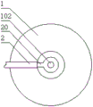
FIG. 2 is a top view of the connection relationship between the conductive gasket and the convex plate of the present invention;
FIG. 3 is a top view of the convex plate and the internal structure of the present invention;
fig. 4 is the bottom schematic view of the local structure of the bolt and the hexagonal concave block of the present invention.
The reference numbers in the figures illustrate:
1 convex plate, 2 grounding wires, 10 cylinders, 101 notches, 20 conductive gaskets, 102 thread grooves, 3 conical rods, 30 auger pieces, 103 bolts and 1030 hexagonal concave blocks.
Detailed Description
The technical solutions in the embodiments of the present invention will be described clearly and completely with reference to the accompanying drawings in the embodiments of the present invention, and it is obvious that the described embodiments are only some embodiments of the present invention, not all embodiments. Based on the embodiments in the present invention, all other embodiments obtained by a person skilled in the art without creative work belong to the protection scope of the present invention.
In the description of the present invention, it is to be noted that, unless otherwise explicitly specified or limited, the terms "mounted", "provided", "sleeved/connected", "connected", and the like are to be understood in a broad sense, such as "connected", which may be fixedly connected, detachably connected, or integrally connected; can be mechanically or electrically connected; they may be connected directly or indirectly through intervening media, or they may be interconnected between two elements. The specific meaning of the above terms in the present invention can be understood in specific cases to those skilled in the art.
Referring to fig. 1-4, a small current grounding positioning device comprises a convex plate 1 and a grounding wire 2, wherein a cylinder 10 is fixedly connected to the inner side surface of a convex opening at the upper end of the convex plate 1, an opening 101 is formed in the front side of the convex opening of the convex plate 1, a conductive gasket 20 of the grounding wire 2 is clamped into the convex opening along the opening 101, the conductive gasket 20 is placed on the surface of the cylinder 10, a thread groove 102 is formed in the cylinder 10, a bolt 103 is connected in the thread groove 102 in a connecting mode, the bolt 103 is connected to the surface of the conductive gasket 20 in a pressing mode, a taper rod 3 is fixed to the lower surface of the cylinder 10, and a packing auger piece 30.
Referring to fig. 1-4, the surface of the upper end of the bolt 103 is fixedly connected with a hexagonal concave block 1030, the hexagonal concave block 1030 is made of hard rubber, so that the bolt can be conveniently twisted by a wrench and can be insulated, the length of the conical rod 3 is not less than twenty centimeters, after the bolt is twisted and driven into the ground, the supporting force is higher, the cylinder 10 and the conical rod 3 are made of iron and can conduct electricity, the convex plate 1 is of a convex round structure and made of hard rubber, and the convex plate 1 is an exposed part of the ground surface and can be insulated.
When the grounding device is used, a cylinder 10 is fixedly connected to the inner side surface of a convex opening at the upper end of a convex plate 1, a conical rod 3 is fixed to the lower surface of the cylinder 10, an auger piece 30 is arranged outside the conical rod 3, the cylinder 10 and the conical rod 3 are made of iron materials and can conduct electricity for a grounding conductor, when the grounding device is used, the conical rod 3 is driven into the ground in a rotating mode, the auger piece 30 drills into the ground for fixing and supporting, the auger piece is convenient to use, an opening 101 is formed in the front side of the convex opening of the convex plate 1, a conductive gasket 20 of a grounding wire 2 is clamped into the convex opening along the opening 101, the conductive gasket 20 is placed on the surface of the cylinder 10, a thread groove 102 is formed in the cylinder 10, a bolt 103 is connected into the thread groove 102 of the cylinder 10;
the upper end surface fixed connection of bolt 103 has hexagonal concave piece 1030, and hexagonal concave piece 1030 adopts hard rubber material, is convenient for twist through the spanner, and the tight construction bolt 103 of being convenient for twist can, and hexagonal concave piece 1030 exposes outside, can insulate for the rubber material.
The above description is only the preferred embodiment of the present invention; the scope of the present invention is not limited thereto. Any person skilled in the art should also be able to cover the technical scope of the present invention by replacing or changing the technical solution and the improvement concept of the present invention with equivalents and modifications within the technical scope of the present invention.
Claims (5)
1. The utility model provides a undercurrent ground connection positioner, includes flange (1), earth connection (2), its characterized in that: the utility model discloses a lead screw, including the upper end protruding mouth of flange (1), the protruding mouth front side of flange (1) establishes opening (101), in the conductive gasket (20) of earth connection (2) advances the protruding mouth along opening (101) card, conductive gasket (20) are placed on cylinder (10) surface, establish thread groove (102) in cylinder (10), threaded groove (102) in-connection has bolt (103), bolt (103) crimping is on the surface of conductive gasket (20), cylinder (10) lower fixed surface has awl pole (3), awl pole (3) are equipped with auger piece (30) outward.
2. A low current grounding alignment device as claimed in claim 1, wherein: the upper end surface of the bolt (103) is fixedly connected with a hexagonal concave block (1030), and the hexagonal concave block (1030) is made of hard rubber.
3. A low current grounding alignment device as claimed in claim 1, wherein: the length of the taper rod (3) is not less than twenty centimeters.
4. A low current grounding alignment device as claimed in claim 1, wherein: the cylinder (10) and the conical rod (3) are made of iron.
5. A low current grounding alignment device as claimed in claim 1, wherein: the convex plate (1) is of a convex round structure and is made of hard rubber.
Priority Applications (1)
| Application Number | Priority Date | Filing Date | Title |
|---|---|---|---|
| CN201922165928.6U CN211453907U (en) | 2019-12-06 | 2019-12-06 | Low-current grounding positioning device |
Applications Claiming Priority (1)
| Application Number | Priority Date | Filing Date | Title |
|---|---|---|---|
| CN201922165928.6U CN211453907U (en) | 2019-12-06 | 2019-12-06 | Low-current grounding positioning device |
Publications (1)
| Publication Number | Publication Date |
|---|---|
| CN211453907U true CN211453907U (en) | 2020-09-08 |
Family
ID=72316149
Family Applications (1)
| Application Number | Title | Priority Date | Filing Date |
|---|---|---|---|
| CN201922165928.6U Active CN211453907U (en) | 2019-12-06 | 2019-12-06 | Low-current grounding positioning device |
Country Status (1)
| Country | Link |
|---|---|
| CN (1) | CN211453907U (en) |
-
2019
- 2019-12-06 CN CN201922165928.6U patent/CN211453907U/en active Active
Similar Documents
| Publication | Publication Date | Title |
|---|---|---|
| CN201533025U (en) | Electric power grounding grid | |
| CN203721905U (en) | Grounding conductive device for spin welding | |
| CN205429186U (en) | Extrusion formula lightning ground connection connecting piece | |
| CN202042820U (en) | Puncture wire clip conveying rod | |
| CN204516914U (en) | Earthing device when distribution line and equipment interruption maintenance | |
| CN202772275U (en) | Anti-winding device for multiple grounding wires during steel pipe welding process | |
| CN202523948U (en) | Movable grounding protection device for electric welding equipment | |
| CN201483176U (en) | Welded pipe turntable grounding bracket | |
| CN205985410U (en) | Meet ground wire device in a flexible way | |
| CN207852953U (en) | A kind of square grounding device for electric force pole tower | |
| CN204947109U (en) | Spiral earth electrode and erecting device | |
| CN214625414U (en) | Grounding device for electric tower | |
| CN209625964U (en) | A kind of transformer connection mechanism | |
| CN105356085A (en) | Electric power construction grounding device | |
| CN103762517B (en) | High-voltage ground wire installation method | |
| CN203278151U (en) | T-shaped compression type strain clamp for power transmission conductor on power transmission line tower | |
| CN204596989U (en) | A kind of power cable on line joint | |
| CN216648778U (en) | Device for grounding wire of electric welding machine | |
| CN223785331U (en) | Three-phase short-circuit grounding device for underground electrical switches in coal mines | |
| CN115764347A (en) | A grounding device for flexible direct current transmission | |
| CN202585794U (en) | Grounding jointing clamp | |
| CN205429296U (en) | Novel a cable connecting terminal for pull out fast and insert | |
| CN203150740U (en) | Ground wire clamp | |
| CN211655111U (en) | Improved generation earth connection connects | |
| CN222637673U (en) | A grounding rod with conversion function |
Legal Events
| Date | Code | Title | Description |
|---|---|---|---|
| GR01 | Patent grant | ||
| GR01 | Patent grant |