CN211450130U - Measuring device is used in civil engineering construction - Google Patents
Measuring device is used in civil engineering construction Download PDFInfo
- Publication number
- CN211450130U CN211450130U CN201922315487.3U CN201922315487U CN211450130U CN 211450130 U CN211450130 U CN 211450130U CN 201922315487 U CN201922315487 U CN 201922315487U CN 211450130 U CN211450130 U CN 211450130U
- Authority
- CN
- China
- Prior art keywords
- adjusting rod
- threaded hole
- civil engineering
- measuring device
- engineering construction
- Prior art date
- Legal status (The legal status is an assumption and is not a legal conclusion. Google has not performed a legal analysis and makes no representation as to the accuracy of the status listed.)
- Expired - Fee Related
Links
- 238000010276 construction Methods 0.000 title claims abstract description 16
- 238000005259 measurement Methods 0.000 description 3
- 238000012986 modification Methods 0.000 description 2
- 230000004048 modification Effects 0.000 description 2
- 210000003781 tooth socket Anatomy 0.000 description 2
- 230000009286 beneficial effect Effects 0.000 description 1
- 238000010586 diagram Methods 0.000 description 1
- 230000000694 effects Effects 0.000 description 1
- 238000003780 insertion Methods 0.000 description 1
- 230000037431 insertion Effects 0.000 description 1
- 238000000034 method Methods 0.000 description 1
Images



Landscapes
- Investigation Of Foundation Soil And Reinforcement Of Foundation Soil By Compacting Or Drainage (AREA)
Abstract
The utility model relates to a civil engineering technical field specifically is a measuring device is used in civil engineering construction, the device comprises a device body, device body bottom is equipped with first regulation pole, the top sliding connection of first regulation pole has the base, the one end of base is equipped with fixed crank, the bottom hinged joint of base has three foot rest, first screw hole and second screw hole have been seted up on the top of first regulation pole, the lift crank is installed on the top of first regulation pole, the inside sliding connection of first regulation pole has the second to adjust the pole, the top of second regulation pole is equipped with screw thread portion and handle, the tooth's socket has been seted up on the top of second regulation pole, the bottom of second regulation pole is equipped with the fixed plate and removes the wheel, be connected through the connecting rod between second regulation pole and the foot rest. The utility model discloses, can highly adjust the device, can fold the device after using, alone just can easily remove this device, very convenient laborsaving improves work efficiency.
Description
Technical Field
The utility model relates to a civil engineering technical field specifically is a measuring device is used in civil engineering construction.
Background
In the civil engineering construction process, frequent measurement is needed, the measurement is a very important ring in the civil engineering, the construction quality is directly influenced, the most common precise instruments are a total station, a theodolite, a level and the like, the level generally needs to use a tripod in the instruments, so a measuring person often needs to carry the tripod, the traditional tripod is large in size and heavy, the movement is very laborious, and much inconvenience is brought to the measuring person.
Disclosure of Invention
An object of the utility model is to provide a measuring device is used in civil engineering construction to solve the tradition tripod that provides in the above-mentioned background art bulky, heavier, very hard problem when removing.
In order to achieve the above object, the utility model provides a following technical scheme:
a measuring device for civil engineering construction comprises a measuring device for civil engineering construction, which comprises a device body, wherein a first adjusting rod is arranged at the bottom end of the device body, the top end of the first adjusting rod is connected with a base in a sliding way, one end of the base is provided with a fixed crank, the bottom end of the base is hinged with three foot rests, the top end of the first adjusting rod is provided with a first threaded hole and a second threaded hole, the top end of the first adjusting rod is provided with a lifting crank, the inside of the first adjusting rod is connected with a second adjusting rod in a sliding way, the top end of the second adjusting rod is provided with a threaded part and a handle, the top end of the second adjusting rod is provided with a tooth socket, the bottom of the second adjusting rod is provided with a fixed plate and a moving wheel, the second adjusting rod is connected with the foot rests through connecting rods, and, the second is adjusted the pole and is three the bottom of foot rest all welded fastening has the connecting piece, the inside fixed connecting strip that is provided with of connecting piece, the connecting strip with the through-hole rotates to be connected.
Preferably, the lifting crank is rotatably connected with the first adjusting rod, the lifting crank is provided with a gear and a fixing screw hole, and the gear is meshed with the tooth groove.
Preferably, one side of the top end of the first adjusting rod is provided with a third threaded hole, the center of the third threaded hole and the center of the fixing screw hole are located on the same axis, and the third threaded hole is fixedly connected with the fixing screw hole through a fixing bolt.
Preferably, one end of the fixed crank is provided with a fixing screw rod, the fixing screw rod is in threaded connection with the first threaded hole and the second threaded hole, and the second threaded hole is higher than the first threaded hole.
Preferably, the fixing plate is provided with three fixing holes, and the fixing holes are in insertion fit with the bottom ends of the foot rests.
Preferably, the bottom of handle is equipped with two connecting blocks, second regulation pole top both sides are equipped with two spread grooves, the connecting block with the spread groove is rotated and is connected.
Compared with the prior art, the beneficial effects of the utility model are that:
the utility model discloses an in, through the lift crank that sets up, can highly adjust the device, through rotating fixed crank, the loose set screw soon, effect between connecting rod and the connecting piece in addition makes and draws close each other between the three foot rest, can fold the device after the use, and the fixed plate of setting can be fixed three foot rest, and the pulling handle is through removing the removal the device that the wheel just can relax alone, very convenient laborsaving, improvement work efficiency.
Drawings
Fig. 1 is a schematic view of the overall assembly structure of the present invention;
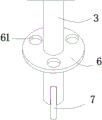
fig. 2 is a schematic structural view of a fixing plate of the present invention;
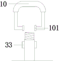
fig. 3 is a schematic view of the structure of the handle of the present invention;
FIG. 4 is a schematic view of the lifting crank of the present invention;
FIG. 5 is a schematic view of the structure of the connecting member and the connecting rod of the present invention
FIG. 6 is a schematic view of the structure at A in FIG. 1;
fig. 7 is a schematic structural diagram at B in fig. 1.
In the figure: 1. a device body; 2. a first adjusting lever; 21. a first threaded hole; 22. a second threaded hole; 23. a lifting crank; 231. a gear; 232. fixing screw holes; 24. a third threaded hole; 3. a second adjusting rod 31, a thread part; 32. a tooth socket; 33. connecting grooves; 4. a base; 5. a foot rest; 6. a fixing plate; 61. a fixing hole; 7. a moving wheel; 8. a connecting rod; 81. a through hole; 9. a connecting member; 91. a connecting strip; 10, a handle; 101. connecting blocks; 11. fixing a crank; 111 hold the screws.
Detailed Description
The technical solutions in the embodiments of the present invention will be described clearly and completely with reference to the accompanying drawings in the embodiments of the present invention, and it is obvious that the described embodiments are only some embodiments of the present invention, not all embodiments. Based on the embodiments in the present invention, all other embodiments obtained by a person skilled in the art without creative work belong to the protection scope of the present invention.
In the description of the present invention, it should be understood that the terms "center", "center line", "longitudinal", "lateral", "length", "width", "thickness", "depth", "up", "down", "front", "back", "left", "right", "vertical", "horizontal", "top", "bottom", "inner", "outer", "clockwise", "counterclockwise", etc. indicate the orientation or positional relationship based on the orientation or positional relationship shown in the drawings, and are only for convenience of description and simplicity of description, and are not intended to indicate or imply that the referenced device or element must have a particular orientation, be constructed and operated in a particular orientation, and therefore should not be taken as limiting the invention, in the description of the present invention, "a plurality" means two or more unless specifically defined otherwise.
Example 1
A measuring device for civil engineering construction, in order to solve the problems of large volume, heavy weight and great labor consumption during movement of the traditional tripod, as a preferred embodiment, as shown in figure 1, figure 2, figure 3, figure 4, figure 5, figure 6 and figure 7, the measuring device comprises a device body 1, a first adjusting rod 2 is arranged at the bottom end of the device body 1, a base 4 is slidably connected at the top end of the first adjusting rod 2, a fixed crank 11 is arranged at one end of the base 4, three foot rests 5 are hinged at the bottom end of the base 4, a first threaded hole 21 and a second threaded hole 22 are arranged at the top end of the first adjusting rod 2, a lifting crank 23 is arranged at the top end of the first adjusting rod 2, the lifting crank 23 is rotatably connected with the first adjusting rod 2, a gear 231 and a fixed threaded hole 232 are arranged on the lifting crank 23, a second adjusting rod 3 is slidably connected inside the first adjusting rod 2, a threaded part 31 and a handle 10 are arranged at the top part of the second, tooth's socket 32 has been seted up on the top of second regulation pole 3, gear 231 is connected with tooth's socket 32 meshing, be convenient for adjust the height of pole 3 to the second and adjust, the bottom that the pole 3 was adjusted to the second is equipped with fixed plate 6 and removes wheel 7, the second is adjusted and is connected through connecting rod 8 between pole 3 and the foot rest 5, through-hole 81 has been seted up at connecting rod 8's both ends, the second is adjusted the equal welded fastening in bottom of pole 3 and three foot rest 5 and is had connecting piece 9, the inside fixed connecting strip 91 that is provided with of connecting piece 9, connecting strip 91 rotates with through-hole 81 to be connected, be convenient.
In this example, the bottom of handle 10 is equipped with two connecting blocks 101, and second regulation pole 3 top both sides are equipped with two spread groove 33, and connecting block 101 is connected with spread groove 33 rotation, is convenient for install surveyor's level and mobile device body 1.
Furthermore, a third threaded hole 24 is formed in one side of the top end of the first adjusting rod 2, the center of the third threaded hole 24 and the center of the fixing threaded hole 232 are located on the same axis, and the third threaded hole 24 and the fixing threaded hole 232 are fixedly connected through a fixing bolt 25, so that the first adjusting rod 2 and the lifting crank 23 are fixed after adjustment.
Specifically, one end of the fixed crank 11 is provided with a fixing screw 111, the fixing screw 111 is in threaded connection with a first threaded hole 21 and a second threaded hole 22, and the second threaded hole 22 is higher than the first threaded hole 21, so that the first adjusting rod 2 and the base 4 are fixed after adjustment.
In addition, three fixing holes 61 are formed in the fixing plate 6, and the fixing holes 61 are matched with the bottom ends of the foot rests 5 in an inserting mode, so that the three accommodated foot rests 5 can be fixed.
When the utility model is used, the level gauge can be fixedly arranged on the device body 1 through the arranged thread part 31, and the height of measurement can be adjusted by shaking the lifting crank 23; when the device is stored, one foot stool 5 of the device is taken as a supporting point to incline the device body 1, the fixed crank 11 is rotated, the fixing screw 111 is screwed out of the first threaded hole 21, the first adjusting rod 2 is pushed downwards, the foot stool 5 is folded towards the 2 directions of the first adjusting rod through the rotating fit of the connecting rod 8 and the connecting piece 9, the fixing hole 61 in the fixing plate 6 is matched with the bottom of the foot stool 5 through rotating the lifting crank 23, then the fixing bolt 25 is screwed into the third threaded hole 24 and the fixing threaded hole 232, the fixing screw 111 is screwed into the second threaded hole 22, the storage of the device body 1 is completed, the pull handle is pulled, and the device can be easily moved by means of the moving wheel 7 at the bottom.
The foregoing shows and describes the general principles, essential features, and advantages of the invention. It should be understood by those skilled in the art that the present invention is not limited by the above embodiments, and the description in the above embodiments and the description is only preferred examples of the present invention, and is not intended to limit the present invention, and that the present invention can have various changes and modifications without departing from the spirit and scope of the present invention, and these changes and modifications all fall into the scope of the claimed invention. The scope of the invention is defined by the appended claims and equivalents thereof.
Claims (6)
1. The utility model provides a measuring device is used in civil engineering construction, includes device body (1), its characterized in that: the device is characterized in that a first adjusting rod (2) is arranged at the bottom end of the device body (1), the top end of the first adjusting rod (2) is connected with a base (4) in a sliding manner, one end of the base (4) is provided with a fixed crank (11), the bottom end of the base (4) is hinged with three foot rests (5), the top end of the first adjusting rod (2) is provided with a first threaded hole (21) and a second threaded hole (22), the top end of the first adjusting rod (2) is provided with a lifting crank (23), the interior of the first adjusting rod (2) is connected with a second adjusting rod (3) in a sliding manner, the top end of the second adjusting rod (3) is provided with a threaded part (31) and a handle (10), the top end of the second adjusting rod (3) is provided with a tooth groove (32), the bottom of the second adjusting rod (3) is provided with a fixed plate (6) and a moving wheel (7), and the second adjusting rod (3) is, through-hole (81) have been seted up at the both ends of connecting rod (8), second is adjusted pole (3) and three the equal welded fastening in bottom of foot rest (5) has connecting piece (9), the inside of connecting piece (9) is fixed and is provided with connecting strip (91), connecting strip (91) with through-hole (81) are rotated and are connected.
2. The measuring device for civil engineering construction according to claim 1, characterized in that: the lifting crank (23) is rotationally connected with the first adjusting rod (2), the lifting crank (23) is provided with a gear (231) and a fixed screw hole (232), and the gear (231) is meshed with the tooth groove (32).
3. The measuring device for civil engineering construction according to claim 2, characterized in that: one side of the top end of the first adjusting rod (2) is provided with a third threaded hole (24), the center of the third threaded hole (24) and the center of the fixing threaded hole (232) are located on the same axis, and the third threaded hole (24) is fixedly connected with the fixing threaded hole (232) through a fixing bolt (25).
4. The measuring device for civil engineering construction according to claim 1, characterized in that: one end of the fixed crank (11) is provided with a fixed screw (111), the fixed screw (111) is in threaded connection with the first threaded hole (21) and the second threaded hole (22), and the second threaded hole (22) is higher than the first threaded hole (21).
5. The measuring device for civil engineering construction according to claim 1, characterized in that: three fixing holes (61) are formed in the fixing plate (6), and the fixing holes (61) are matched with the bottom ends of the foot frames (5) in an inserting mode.
6. The measuring device for civil engineering construction according to claim 1, characterized in that: the bottom of handle (10) is equipped with two connecting blocks (101), second regulation pole (3) top both sides are equipped with two spread groove (33), connecting block (101) with spread groove (33) rotate and are connected.
Priority Applications (1)
| Application Number | Priority Date | Filing Date | Title |
|---|---|---|---|
| CN201922315487.3U CN211450130U (en) | 2019-12-21 | 2019-12-21 | Measuring device is used in civil engineering construction |
Applications Claiming Priority (1)
| Application Number | Priority Date | Filing Date | Title |
|---|---|---|---|
| CN201922315487.3U CN211450130U (en) | 2019-12-21 | 2019-12-21 | Measuring device is used in civil engineering construction |
Publications (1)
| Publication Number | Publication Date |
|---|---|
| CN211450130U true CN211450130U (en) | 2020-09-08 |
Family
ID=72295731
Family Applications (1)
| Application Number | Title | Priority Date | Filing Date |
|---|---|---|---|
| CN201922315487.3U Expired - Fee Related CN211450130U (en) | 2019-12-21 | 2019-12-21 | Measuring device is used in civil engineering construction |
Country Status (1)
| Country | Link |
|---|---|
| CN (1) | CN211450130U (en) |
-
2019
- 2019-12-21 CN CN201922315487.3U patent/CN211450130U/en not_active Expired - Fee Related
Similar Documents
| Publication | Publication Date | Title |
|---|---|---|
| CN210771277U (en) | A level tripod for construction project management | |
| CN215981790U (en) | A three-dimensional surveying and mapping auxiliary device for urban municipal engineering | |
| CN212319296U (en) | Measure survey and drawing and use measuring apparatu support | |
| CN211010644U (en) | Portable supporting device for leveling measurement | |
| CN208253114U (en) | Tripod is used in a kind of measurement | |
| CN214010322U (en) | Measuring instrument holder for civil engineering | |
| CN207487674U (en) | One kind is used for topographic portable rack | |
| CN217327982U (en) | Civil engineering is telescopic bracket for measurement | |
| CN215173784U (en) | On-spot mapping device of engineering cost | |
| CN212539191U (en) | Engineering supervision verticality detection device | |
| CN210714063U (en) | Camping bracket for geological exploration | |
| CN220153574U (en) | A kind of tower ruler used for land resources surveying and mapping | |
| CN223062350U (en) | Electric power emergency repair cat ladder | |
| CN211994890U (en) | Foundation planning device for building planning engineering | |
| CN220891495U (en) | Site mapping device | |
| CN219493318U (en) | Fixing structure for pipe rack installation | |
| CN218185609U (en) | Roman umbrella with detachable tea table | |
| CN220832294U (en) | Support frame convenient to carry | |
| CN206016199U (en) | A kind of adjustable trowel | |
| CN215215597U (en) | Surveying and mapping tool for engineering cost | |
| CN216305480U (en) | Building steel structure support column | |
| CN111504266A (en) | A portable foldable level | |
| CN210774049U (en) | Open-air portable multi-functional survey and drawing platform | |
| CN213418481U (en) | Building site stair pour and use support frame | |
| CN222745640U (en) | Template supporting structure |
Legal Events
| Date | Code | Title | Description |
|---|---|---|---|
| GR01 | Patent grant | ||
| GR01 | Patent grant | ||
| CF01 | Termination of patent right due to non-payment of annual fee | ||
| CF01 | Termination of patent right due to non-payment of annual fee |
Granted publication date: 20200908 Termination date: 20211221 |