CN211447265U - Laminated plate type edge member and solid shear wall horizontal connection structure - Google Patents
Laminated plate type edge member and solid shear wall horizontal connection structure Download PDFInfo
- Publication number
- CN211447265U CN211447265U CN201921572815.1U CN201921572815U CN211447265U CN 211447265 U CN211447265 U CN 211447265U CN 201921572815 U CN201921572815 U CN 201921572815U CN 211447265 U CN211447265 U CN 211447265U
- Authority
- CN
- China
- Prior art keywords
- plate type
- shear wall
- shaped
- prefabricated
- solid shear
- Prior art date
- Legal status (The legal status is an assumption and is not a legal conclusion. Google has not performed a legal analysis and makes no representation as to the accuracy of the status listed.)
- Active
Links
Images


Abstract
Laminated plate type edge member and solid shear wall horizontal connection structure. At present, the economic benefit and the social benefit generated by different assembly type building construction modes are different. The edge member of the reinforced concrete shear wall structure at the present stage adopts a cast-in-place mode, and the cast-in-place quantity is large on site. The utility model provides a superimposed sheet formula edge member and solid shear wall horizontal connection structure, its constitution includes: the prefabricated composite plate type edge component comprises a prefabricated composite plate type edge component (1) and a solid shear wall (2), wherein the prefabricated composite plate type edge component is a straight line type edge component or a T type, an L type, a Z type or a U type formed by the straight line type edge component, the straight line type edge component is formed by two layers of prefabricated concrete thin plates (3), a cavity is formed between the two layers of prefabricated concrete thin plates, longitudinal reinforcements (4) and stirrups (5) of the edge component are embedded in the two layers of prefabricated concrete thin plates in a closed ring shape, and the end parts of the prefabricated composite plate type edge component are connected with the solid shear wall. The utility model is used for the construction field.
Description
The technical field is as follows:
the utility model relates to a superimposed sheet type edge member and solid shear wall horizontal connection structure.
Background art:
compared with the traditional cast-in-place structure, the prefabricated building has obvious technical advantages of saving labor, templates and machinery, improving the quality of survival, reducing emission and pollution, saving construction period and cost, but the economic benefit and the social benefit generated by different construction modes of the prefabricated building are different. At the present stage, the edge member of the reinforced concrete shear wall structure adopts a cast-in-place form, the assembly type technology is not perfect enough, the cast-in-place quantity on site is large, even if the edge member of the shear wall structure adopts a prefabricated form, the member is solid, most of the members adopt sleeve connection, the cost is high, the grouting connection quality is difficult to guarantee, and potential safety hazards are caused to the engineering quality.
The utility model has the following contents:
the utility model aims at providing a superimposed sheet formula edge member and solid shear force wall horizontally connect structure.
The above purpose is realized by the following technical scheme:
coincide board-like border member and solid shear force wall horizontal connection structure, its constitution includes: the shear wall comprises a prefabricated overlapped plate type edge component and a solid shear wall, wherein the prefabricated overlapped plate type edge component is a straight line type edge component or a T type, an L type, a Z type or a U type formed by the straight line type edge component, the straight line type edge component is formed by two layers of prefabricated concrete thin plates, a cavity is formed between the two layers of prefabricated concrete thin plates, longitudinal reinforcements and stirrups of the edge component are embedded in the two layers of prefabricated concrete thin plates, the stirrups are closed rings, the end parts of the prefabricated overlapped plate type edge component are connected with the solid shear wall, horizontal reinforcements of the solid shear wall are annular, extended straight strips or extended opposite buckling L types, and the extended straight strips or extended opposite buckling L-shaped reinforcements extend into the cavity inside the overlapped plate type edge component and are fixed.
The composite plate type edge member and solid shear wall horizontal connecting structure is characterized in that a horizontal annular reinforcing steel bar extending outwards from the solid shear wall extends into a cavity of the composite plate type edge member and is jointed with a closed annular stirrup of a prefabricated composite plate type edge member to form a joint gap, and a pin joint longitudinal rib is inserted into the joint gap to form a pin joint structure.
The laminated plate type edge member and solid shear wall horizontal connecting structure is characterized in that the solid shear wall horizontal annular reinforcing steel bar is connected with the prefabricated laminated plate type edge member annular stirrup through an additional reinforcing steel bar ring, the additional reinforcing steel bar ring is respectively connected with the solid shear wall horizontal annular reinforcing steel bar and the laminated plate type edge member annular stirrup to form a connecting gap, the two gaps are respectively inserted with a pin connecting longitudinal bar to form a pin connecting structure,
laminated plate type edge member and solid shear wall horizontal connection structure, prefabricated laminated plate type edge member cavity in set up U type reinforcing bar, U type reinforcing bar and the handing-over of the horizontal cyclic annular reinforcing bar of solid shear wall form the handing-over space the space in insert the pin joint and indulge the muscle and form the pin joint structure.
The laminated plate type edge member and solid shear wall horizontal connection structure is characterized in that a truss steel bar, a tie bar and a tie piece are arranged in a cavity of the prefabricated laminated plate type edge member according to the size of the member, the truss steel bar, the tie bar and the tie piece are embedded into two layers of prefabricated concrete sheets, and the pin joint longitudinal bar is a straight steel bar or an annular steel bar.
The overlapped plate type edge member and solid shear wall horizontal connection structure is characterized in that the overlapped plate type L-shaped, T-shaped, Z-shaped and U-shaped edge members are formed by combining and splicing straight-line-shaped edge members, the overlapped plate type L-shaped edge members are combined by adjusting the width of a straight-line-shaped edge member sheet and the extension length of an annular reinforcing steel bar, the overlapped plate type T-shaped edge members are combined by arranging a seam at the middle part of a single-side sheet of the straight-line-shaped edge member and adjusting the extension length of the annular reinforcing steel bar with the other straight-line-shaped edge member, connecting pieces are arranged on the straight-line-shaped edge members needing to be combined, and the edge members are temporarily fixed according to the form of the edge members before the overlapped plate type edge members are installed to form the straight-line-shaped, L-shaped, T-shaped, Z-shaped and U-shaped.
The utility model has the advantages that:
1. the utility model discloses shear force wall structure edge component and solid shear force wall connection structure are simple, and it is convenient to install, avoids the reinforcement to need reserve the disadvantage of a large amount of cast-in-place sections, improves the assembly rate, shortens construction period, saves the construction cost.
2. The utility model provides a reinforced concrete shear wall structure edge member cost of manufacture, the drawback that installation cost is high. Most longitudinal steel bars of edge components of the reinforced concrete shear wall structure at the present stage are connected through sleeves, all the longitudinal steel bars need to be connected, the sleeve cost, the prefabricated component manufacturing cost, the installation labor cost, the grouting material cost and the grouting labor cost are higher, the grouting process has higher requirements on the environment, the connection quality is not easy to guarantee, the grouting fullness degree detection difficulty is higher, and potential safety hazards are caused to the engineering quality.
3. The utility model discloses the board-like edge member both sides of coincide are the precast concrete sheet metal, and the centre is cavity cast in situ concrete, and structural integrity is good, and the great concrete placement compactness of inside cavity is high.
4. The utility model discloses the prefabricated sheet metal in coincide board-like marginal component both sides acts as the template and need not formwork once more, and construction convenience reduces the carpenter's work volume and the operation degree of difficulty, saves the cost of labor.
5. The utility model discloses the prefabricated component quality is light, hangs heavily requiring lowly to on-the-spot hoist and mount machinery, sparingly purchases and lease cost from mechanical lectotype.
6. The utility model provides an assembled reinforced concrete structure, the drawback of L type, T type and other form hidden posts cast-in-place usually reduces on-spot formwork, ties up the muscle, pours concrete's work load, improves the construction speed, shortens key line time, reduction of erection time, reduction financial cost.
7. The utility model discloses reduce cast-in-place volume, the erection construction is simple, reduces job site workman's recruitment quantity, solves the recruitment problem of wastefully.
8. The utility model discloses prefabricated coincide board-like edge member provides the way for increasing substantially the assembly rate, improves china's assembled reinforced concrete assembly technique level.
9. The utility model discloses the edge component separately makes with the shear force wall, and the edge component size is standardized, and the component commonality is strong can realize the prefabricated component commercialization, and the component is produced in advance and deposit production, improves the utilization ratio of production prefabricated component template, is favorable to occupying market, improves market share.
10. The utility model discloses the standardized storage and the transportation of being convenient for of edge component avoids present stage because component factory stock dump is great, and prefabricated component puts the unreasonable phenomenon that causes the searching component difficulty, avoids hindering on-the-spot installation progress.
Description of the drawings:
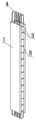
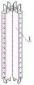
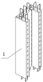
FIG. 1 is a schematic view I of a prefabricated linear overlapped plate type edge member of the present invention;
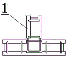
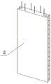
FIG. 2 is a schematic view of a prefabricated linear overlapped plate type edge member of the present invention;
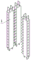
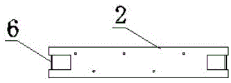
FIG. 3 is a schematic view III of the prefabricated linear overlapped plate type edge member of the present invention;
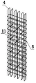
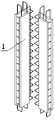
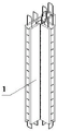
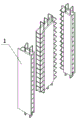
FIG. 4 is a schematic view of a steel reinforcement cage arranged inside the prefabricated overlapped plate type edge member of the present invention;
FIG. 5 is a schematic view of a steel reinforcement cage with trusses arranged inside the prefabricated overlapped plate type edge member of the present invention;
FIG. 6 is a schematic view of the truss reinforcement of the present invention;
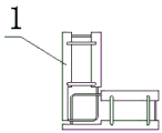
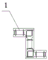
FIG. 7 is a schematic plan view of the prefabricated laminated L-shaped edge member of the present invention;
FIG. 8 is an exploded view of the prefabricated laminated L-shaped edge member of the present invention;
FIG. 9 is a schematic view of the assembly of the prefabricated laminated L-shaped edge member of the present invention;
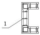
FIG. 10 is a schematic plan view of a prefabricated laminated T-shaped edge member of the present invention;
FIG. 11 is an exploded view of the prefabricated laminated T-shaped edge member of the present invention;
FIG. 12 is a schematic view of the assembly of the prefabricated laminated T-shaped edge member of the present invention;
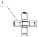
fig. 13 is a schematic plan view of a prefabricated overlapped plate type ten-shaped edge member of the present invention;
fig. 14 is an exploded view of a prefabricated overlapped plate type ten-shaped edge member of the present invention;
FIG. 15 is a schematic view of the prefabricated overlapped plate type cross-shaped edge member assembly of the present invention;
fig. 16 is a schematic plan view of a prefabricated laminated plate type Z-shaped edge member of the present invention;
FIG. 17 is an exploded view of the prefabricated laminated Z-shaped edge member of the present invention;
FIG. 18 is a schematic view of the assembly of the prefabricated laminated Z-shaped edge member of the present invention;
FIG. 19 is a schematic plan view of a U-shaped edge member of the present invention;
FIG. 20 is an exploded view of the U-shaped edge member of the present invention;
FIG. 21 is a schematic view of the assembly of the prefabricated overlapped plate U-shaped edge members of the present invention;
fig. 22 is a schematic axial view of the end of the solid shear wall with a groove according to the present invention;
fig. 23 is a schematic plan view of the end portion of the solid shear wall with the groove of the present invention;
fig. 24 is a schematic plan view of the solid shear wall end portion overhanging ring rib of the present invention;
fig. 25 is a schematic view of the solid shear wall end portion overhanging ring rib shaft of the present invention;
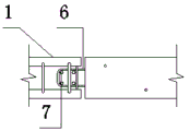
fig. 26 is a schematic view of the horizontal connecting pin connection between the prefabricated solid shear wall and the prefabricated overlapped plate type edge member of the present invention;
fig. 27 is a schematic view of the pin joint connection between the prefabricated solid shear wall and the horizontal connecting additional reinforcing ring of the prefabricated overlapped plate type edge member of the present invention;
fig. 28 is a schematic view of the pin joint connection of the prefabricated solid shear wall and the prefabricated laminated plate type edge member horizontal connection wall body additional reinforcing steel bar ring;
fig. 29 is a schematic view of the pin joint connection of the prefabricated solid shear wall and the prefabricated overlapped plate type edge member horizontal connection wall body preformed groove additional U-shaped steel bar;
FIG. 30 is a schematic view of the horizontal connection of the prefabricated solid shear wall and the prefabricated composite plate type edge members with the additional U-shaped steel bar pin joint;
fig. 31 is a schematic view of the cast-in-place concrete in which the vertical bar-shaped steel bars extending outward from the prefabricated solid shear wall are anchored into the cavity of the overlapped plate-type edge member;
fig. 32 is a schematic view of the cast-in-place concrete in which the L-shaped reinforcing bars extending outward from the prefabricated solid shear wall are anchored into the cavity of the overlapped plate-type edge member;
in the figure: 1. the prefabricated composite slab type edge component comprises a prefabricated laminated slab type edge component 2, a solid shear wall 3, two layers of prefabricated concrete sheets 4, longitudinal steel bars 5, stirrups 6, horizontal steel bars of the solid shear wall 7, pin-jointed longitudinal steel bars 8, steel bar rings 9, U-shaped steel bars 10, truss steel bars 11 and tie bars.
The specific implementation mode is as follows:
example 1:
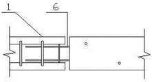
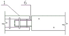
coincide board-like border member and solid shear force wall horizontal connection structure, its constitution includes: the shear wall comprises a prefabricated overlapped plate type edge component 1 and a solid shear wall 2, wherein the prefabricated overlapped plate type edge component is a straight line type edge component or a T type, an L type, a Z type or a U type formed by the straight line type edge component, the straight line type edge component is formed by two layers of prefabricated concrete thin plates 3, a cavity is formed between the two layers of prefabricated concrete thin plates, longitudinal reinforcing steel bars 4 and stirrups 5 of the edge component are embedded in the two layers of prefabricated concrete thin plates, the stirrups are closed rings, the end parts of the prefabricated overlapped plate type edge component are connected with the shear wall, horizontal reinforcing steel bars 6 of the solid shear wall are annular, extended straight bars or extended opposite buckling L types, and the extended straight bars or the extended opposite buckling L type reinforcing steel bars extend into the cavity inside the overlapped plate type edge component and are fixed.
Example 2:
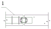
according to the structure for horizontally connecting the overlapped plate type edge member and the solid shear wall in the embodiment 1, the horizontal annular reinforcing steel bars extending outwards from the solid shear wall extend into the cavity of the overlapped plate type edge member and are jointed with the closed annular stirrups of the prefabricated overlapped plate type edge member to form a joint gap, and the pin joint longitudinal ribs 7 are inserted into the joint gap to form a pin joint structure.
Example 3:
the structure for horizontally connecting a laminated plate type edge member and a solid shear wall according to embodiment 1 or 2, wherein the horizontal ring-shaped reinforcing steel bars of the solid shear wall are connected with the ring-shaped stirrups of the prefabricated laminated plate type edge member through additional reinforcing steel bar rings 8, the additional reinforcing steel bar rings are respectively connected with the horizontal ring-shaped reinforcing steel bars of the solid shear wall and the ring-shaped stirrups of the laminated plate type edge member to form connecting gaps, and pin-jointed longitudinal bars are respectively inserted into the two gaps to form a pin-jointed structure.
Example 4:
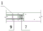
according to the structure for horizontally connecting the laminated plate type edge member and the solid shear wall in the embodiment 1, 2 or 3, the U-shaped steel bar 9 is arranged in the cavity of the prefabricated laminated plate type edge member, the U-shaped steel bar and the horizontal annular steel bar of the solid shear wall are jointed to form a joint gap, and a pin joint longitudinal bar is inserted into the gap to form a pin joint structure.
Example 5:
according to the structure for horizontally connecting the overlapped plate type edge member and the solid shear wall in the embodiment 1, 2, 3 or 4, truss steel bars, tie bars and tie pieces are arranged in a cavity of the prefabricated overlapped plate type edge member according to the size of the member, the truss steel bars 10, the tie bars 11 and the tie pieces are embedded into two layers of prefabricated concrete sheets, and the pin joint longitudinal bars are straight steel bars or annular steel bars.
Example 6:
the structure for horizontally connecting an overlapped plate type edge member and a solid shear wall according to embodiment 1 or 2 or 3 or 4 or 5, wherein the overlapped plate type L-shaped, T-shaped, Z-shaped and U-shaped edge members are formed by combining and splicing straight-line-shaped edge members, the overlapped plate type L-shaped edge members are combined by adjusting the width of a straight-line-shaped edge member sheet and the extension length of an annular reinforcing steel bar, the overlapped plate type T-shaped edge members are combined by arranging a seam at the middle part of a single-side sheet of the straight-line-shaped edge member and adjusting the extension length of the annular reinforcing steel bar by using another straight-line-shaped edge member, a connecting member is arranged on the straight-line-shaped edge member to be combined, and the edge members are temporarily fixed according to the form of the edge members before the overlapped plate type edge members are installed to form the straight-line-shaped, L-shaped, T-shaped, Z-.
The method for horizontally connecting the overlapped plate type edge member and the solid shear wall comprises the steps of installing the prefabricated solid shear wall, chiseling, cleaning, watering and moistening an installation operation surface, adjusting the verticality of a steel bar, placing a cushion block, recording and measuring the elevation of the cushion block, paving seat slurry, wherein the middle of the seat slurry in the wall length direction is slightly higher than the cushion block and ensures that no slurry exists on the cushion block, the amount of the seat slurry is proper to fill the whole slurry layer at the bottom of the wall body, hoisting the wall body in time, aligning a connecting hole at the bottom of the wall body to the shear wall steel bar embedded in the operation surface, installing an inclined support, adjusting the installation position according to a wall body control line and a prefabricated member contour line, adjusting the verticality of the; and assembling the prefabricated overlapped plate type edge components into an L shape, a T shape and other shapes according to the form of the edge components.
Hoisting a laminated plate type edge member, horizontally moving the laminated plate type edge member after the laminated plate type edge member vertically falls down, enabling the external steel bars of the solid shear wall to enter the laminated plate type edge member, enabling the external steel bars of the solid shear wall and the annular stirrups of the laminated plate type edge member to form cross-connecting gaps, adjusting the installation position according to wall control lines and prefabricated member contour lines, adjusting the wall verticality, fixing inclined supports, inserting pin-connected longitudinal bars into the cross-connecting gaps formed by the external steel bars of the solid shear wall and the annular stirrups of the laminated plate type edge member, installing other prefabricated building members such as a laminated beam, a laminated plate and the like, erecting a gap between the solid shear wall and the laminated plate type edge member, pouring concrete and vibrating in the middle cavity of the laminated plate type edge member, and completing the connection of the horizontal connection structure of the laminated plate type edge member and.
Arranging the additional reinforcing ring in the cavity inside the prefabricated laminated plate type edge member or the groove at the end part of the solid shear wall, hoisting and vertically dropping the laminated plate type edge member, adjusting the installation position according to the wall control line and the contour line of the prefabricated component, adjusting the wall verticality, fixing the inclined strut, moving the additional reinforcing steel bar ring to ensure that the additional reinforcing steel bar ring is respectively connected with the prefabricated laminated plate type edge component annular stirrup and the horizontal reinforcing steel bar of the solid shear wall to form a connecting gap, the two gaps are respectively inserted with a pin joint longitudinal bar to form a pin joint structure, other building prefabricated components such as superposed beams and superposed slabs are installed, a gap is installed between a solid shear wall and a superposed plate type edge component, and pouring concrete in the cavity in the middle of the laminated plate type edge member and vibrating to complete the connection of the laminated plate type edge member and the horizontal connection structure of the solid shear wall.
Will U shaped steel muscle set up in the inside cavity of prefabricated coincide board-like edge component, hoist and mount and the board-like edge component of perpendicular whereabouts coincide according to wall body control line and prefabricated component contour line adjustment mounted position, adjust the wall body straightness that hangs down, fixed bearing diagonal moves U shaped steel muscle, makes U shaped steel muscle and solid shear force wall horizontal reinforcement handing-over form handing-over space the space in insert pin joint longitudinal reinforcement, form the pin joint structure, other building prefabricated components such as installation superposed beam, superimposed sheet erect solid shear force wall and coincide board-like edge component intermediate erection gap, pour concrete and vibrate in superimposed board-like edge component middle part cavity, accomplish superimposed board-like edge component and solid shear force wall horizontal connection structure's being connected.
Claims (6)
1. The utility model provides a superimposed sheet formula edge member and solid shear wall horizontal connection structure, its constitution includes: prefabricated superimposed sheet formula border member and solid shear force wall, characterized by: the prefabricated overlapped plate type edge component is a straight line type edge component or a T type, an L type, a Z type or a U type formed by the straight line type edge component, the straight line type edge component is formed by two layers of prefabricated concrete sheets, a cavity is formed between the two layers of prefabricated concrete sheets, longitudinal reinforcements and stirrups of the edge component are embedded in the two layers of prefabricated concrete sheets in a pre-embedded mode, the stirrups are closed rings, the end portion of the prefabricated overlapped plate type edge component is connected with the solid shear wall, horizontal reinforcements of the solid shear wall are annular, overhanging straight bars or overhanging butt-buckled L types, and the overhanging straight bars or the overhanging butt-buckled L types extend into the cavity inside the overlapped plate type edge component and are fixed.
2. A laminated panel edge member to solid shear wall horizontal connection as claimed in claim 1, wherein: the solid shear wall extends out of a horizontal annular steel bar to extend into the cavity of the overlapped plate type edge member and is jointed with the prefabricated overlapped plate type edge member closed annular stirrup to form a joint gap, and a pin joint longitudinal bar is inserted into the joint gap to form a pin joint structure.
3. A laminated panel edge member to solid shear wall horizontal connection according to claim 1 or claim 2, wherein: the horizontal annular reinforcing steel bars of the solid shear wall are connected with the annular stirrups of the prefabricated overlapped plate type edge members through additional reinforcing steel bar rings, the additional reinforcing steel bar rings are respectively connected with the horizontal annular reinforcing steel bars of the solid shear wall and the annular stirrups of the overlapped plate type edge members to form connecting gaps, and pin joint longitudinal bars are respectively inserted into the two gaps to form a pin joint structure.
4. A laminated panel edge member to solid shear wall horizontal connection according to claim 1 or claim 2, wherein: the prefabricated overlapped plate type edge member cavity is internally provided with U-shaped steel bars, the U-shaped steel bars are jointed with horizontal annular steel bars of the solid shear wall to form joint gaps, and pin joint longitudinal bars are inserted into the gaps to form a pin joint structure.
5. A laminated panel edge member to solid shear wall horizontal connection as claimed in claim 2, wherein: the prefabricated overlapped plate type edge member cavity is internally provided with a truss reinforcing steel bar, a tie bar and a tie piece according to the member size, the truss reinforcing steel bar, the tie bar and the tie piece are embedded into two layers of prefabricated concrete sheets, and the pin joint longitudinal steel bar is a straight reinforcing steel bar or an annular reinforcing steel bar.
6. A laminated panel edge member to solid shear wall horizontal connection according to claim 1 or claim 2, wherein: the overlapped plate type L-shaped, T-shaped, Z-shaped and U-shaped edge components are formed by combining and splicing straight-line-shaped edge components, the overlapped plate type L-shaped edge components are combined by adjusting the width of a straight-line-shaped edge component thin plate and the extension length of an annular reinforcing steel bar, the overlapped plate type T-shaped edge components are combined by arranging a seam at the middle part of a single-side thin plate of the straight-line-shaped edge component and adjusting the extension length of the annular reinforcing steel bar with another straight-line-shaped edge component, connecting pieces are arranged on the straight-line-shaped edge components needing to be combined, the edge components are temporarily fixed according to the form of the edge components before the overlapped plate type edge components are installed, and the straight-line-shaped, L-shaped, T-shaped, Z-shaped and U-shaped edge.
Priority Applications (1)
| Application Number | Priority Date | Filing Date | Title |
|---|---|---|---|
| CN201921572815.1U CN211447265U (en) | 2019-09-20 | 2019-09-20 | Laminated plate type edge member and solid shear wall horizontal connection structure |
Applications Claiming Priority (1)
| Application Number | Priority Date | Filing Date | Title |
|---|---|---|---|
| CN201921572815.1U CN211447265U (en) | 2019-09-20 | 2019-09-20 | Laminated plate type edge member and solid shear wall horizontal connection structure |
Publications (1)
| Publication Number | Publication Date |
|---|---|
| CN211447265U true CN211447265U (en) | 2020-09-08 |
Family
ID=72301844
Family Applications (1)
| Application Number | Title | Priority Date | Filing Date |
|---|---|---|---|
| CN201921572815.1U Active CN211447265U (en) | 2019-09-20 | 2019-09-20 | Laminated plate type edge member and solid shear wall horizontal connection structure |
Country Status (1)
| Country | Link |
|---|---|
| CN (1) | CN211447265U (en) |
Cited By (1)
| Publication number | Priority date | Publication date | Assignee | Title |
|---|---|---|---|---|
| CN113026985A (en) * | 2021-03-17 | 2021-06-25 | 中国建筑第五工程局有限公司 | Vertical seam dislocation mutual anchor connection structure of prefabricated shear wall edge member department |
-
2019
- 2019-09-20 CN CN201921572815.1U patent/CN211447265U/en active Active
Cited By (1)
| Publication number | Priority date | Publication date | Assignee | Title |
|---|---|---|---|---|
| CN113026985A (en) * | 2021-03-17 | 2021-06-25 | 中国建筑第五工程局有限公司 | Vertical seam dislocation mutual anchor connection structure of prefabricated shear wall edge member department |
Similar Documents
| Publication | Publication Date | Title |
|---|---|---|
| CN108049498B (en) | The prefabricated post and Prefabricated beam connection structure and method of assembled architecture frame structure | |
| CN100482892C (en) | Lower chord opening beam type corrugated steel web combination beam | |
| CN109339229B (en) | Prefabricated assembled concrete-filled steel tube frame structure of perforation thick liquid anchor | |
| CN206707124U (en) | Prefabricated assembling type reinforced concrete component with joint of steel structure | |
| JP2008274586A (en) | Pillar head construction method | |
| CN113026965A (en) | Prefabricated beam and support-free prefabricated plate connecting joint and construction method | |
| CN211447265U (en) | Laminated plate type edge member and solid shear wall horizontal connection structure | |
| CN113186811A (en) | Pier is assembled in horizontal piecemeal prefabrication based on wet seam | |
| CN112523348A (en) | Quick erection column connecting piece | |
| CN110670770A (en) | Solid shear wall and laminated plate type edge member combined structure and construction method | |
| CN111101645A (en) | Self-in-place reinforced precast concrete wallboard, connecting structure and construction method | |
| CN104032862B (en) | Assembled girder steel seam line L shape mixing coupled wall and construction method thereof | |
| CN211229068U (en) | Solid shear wall and laminated plate type edge member combined structure | |
| CN113294175B (en) | Construction method of tunnel secondary lining structure and tunnel secondary lining structure | |
| CN215629294U (en) | Bent cap structure and pier | |
| CN215211802U (en) | Novel prefabricated floor slab and connecting structure thereof | |
| CN210917941U (en) | Prefabricated superimposed sheet type edge member | |
| CN209779683U (en) | Jigsaw assembled comprehensive pipe gallery | |
| CN110616812A (en) | Laminated plate type edge member and solid shear wall horizontal connection structure and connection method | |
| CN112064824A (en) | Combined-connection prefabricated shear wall system | |
| CN101881051B (en) | Beam-beam connecting node structure | |
| CN215977872U (en) | Overlapped integral prefabricated shear wall edge component | |
| CN113404054A (en) | Cement mixing pile type, cast-in-place pile type crown beam construction method and crown beam system | |
| CN101230673A (en) | Force-bearing type superposed component for concrete building lid | |
| CN211850334U (en) | Prefabricated superimposed sheet type edge member combined structure |
Legal Events
| Date | Code | Title | Description |
|---|---|---|---|
| GR01 | Patent grant | ||
| GR01 | Patent grant |