CN211429108U - A DC planetary gear motor - Google Patents
A DC planetary gear motor Download PDFInfo
- Publication number
- CN211429108U CN211429108U CN202020119640.5U CN202020119640U CN211429108U CN 211429108 U CN211429108 U CN 211429108U CN 202020119640 U CN202020119640 U CN 202020119640U CN 211429108 U CN211429108 U CN 211429108U
- Authority
- CN
- China
- Prior art keywords
- motor
- planetary gear
- worm
- output shaft
- cover plate
- Prior art date
- Legal status (The legal status is an assumption and is not a legal conclusion. Google has not performed a legal analysis and makes no representation as to the accuracy of the status listed.)
- Expired - Fee Related
Links
Images

Landscapes
- Connection Of Motors, Electrical Generators, Mechanical Devices, And The Like (AREA)
Abstract
本实用新型属于减速电机设备技术领域,尤其为一种直流行星齿轮减速电机,针对现有的一体式减速电机难以拆卸导致不便于进行润滑等维护工作的问题,现提出如下方案,其包括壳体,所述壳体一侧开设有安装孔,安装孔内转动安装有总输出轴,总输出轴位于壳体内部的一端固定安装有连接盘,连接盘一侧开设有六个圆形孔,六个圆形孔呈环形等间距设置,六个圆形孔内均转动安装有连接轴,壳体内固定安装有内齿轮并放置有电机,六个连接轴靠近电机的一端均固定安装有行星齿轮,六个行星齿轮均与内齿轮相啮合。本实用新型结构设计合理,方便对减速电机进行拆卸,便于对其传动部件进行润滑等维护工作,便于使用,可靠性高。
The utility model belongs to the technical field of deceleration motor equipment, in particular to a DC planetary gear deceleration motor. In view of the problem that the existing integrated deceleration motor is difficult to disassemble, which leads to inconvenient maintenance work such as lubrication, the following scheme is proposed, which comprises a housing A mounting hole is provided on one side of the housing, and a total output shaft is rotatably installed in the mounting hole. One end of the total output shaft located inside the housing is fixedly installed with a connecting plate, and one side of the connecting plate is provided with six circular holes, six The circular holes are arranged at equal intervals in a ring, the connecting shafts are rotatably installed in the six circular holes, the internal gear is fixedly installed in the casing and the motor is placed, and the end of the six connecting shafts close to the motor is fixedly installed with a planetary gear. All six planetary gears mesh with the internal gear. The utility model has a reasonable structure design, facilitates disassembly of the deceleration motor, facilitates maintenance work such as lubricating the transmission parts thereof, is convenient to use, and has high reliability.
Description
技术领域technical field
本实用新型涉及减速电机设备技术领域,尤其涉及一种直流行星齿轮减速电机。The utility model relates to the technical field of deceleration motor equipment, in particular to a DC planetary gear deceleration motor.
背景技术Background technique
随着现代科技的发展,电机的发展也越来越快,电机的主要作用是产生驱动转矩,作为用电器或各种机械的动力源。现有技术的电机种类很多,有的电机和减速器是分体制作,然后再根据需要进行组装,也有直接将电机和减速器制作为一体结构的。With the development of modern science and technology, the development of motors is also getting faster and faster. The main function of motors is to generate driving torque, which is used as a power source for electrical appliances or various machinery. There are many types of motors in the prior art. Some motors and reducers are made separately and then assembled according to needs, and some are directly made into an integrated structure.
但是,将电机和减速器制作为一体结构时,难以进行拆卸和维护,且传动件的润滑问题较难解决,从而影响减速器的使用寿命,因此我们提出了一种直流行星齿轮减速电机用于解决上述问题。However, when the motor and the reducer are made into one structure, it is difficult to disassemble and maintain, and the lubrication problem of the transmission parts is difficult to solve, which affects the service life of the reducer. Therefore, we propose a DC planetary gear motor for Solve the above problem.
实用新型内容Utility model content
本实用新型的目的是为了解决现有的一体式减速电机难以拆卸导致不便于进行润滑等维护工作的缺点,而提出的一种直流行星齿轮减速电机。The purpose of the utility model is to solve the shortcomings of the existing integrated deceleration motor which is difficult to disassemble and inconvenient for maintenance work such as lubrication, and proposes a DC planetary gear deceleration motor.
为了实现上述目的,本实用新型采用了如下技术方案:In order to achieve the above-mentioned purpose, the utility model adopts the following technical solutions:
一种直流行星齿轮减速电机,包括壳体,所述壳体一侧开设有安装孔,安装孔内转动安装有总输出轴,总输出轴位于壳体内部的一端固定安装有连接盘,连接盘一侧开设有六个圆形孔,六个圆形孔呈环形等间距设置,六个圆形孔内均转动安装有连接轴,壳体内固定安装有内齿轮并放置有电机,六个连接轴靠近电机的一端均固定安装有行星齿轮,六个行星齿轮均与内齿轮相啮合,电机输出轴上固定安装有太阳轮,六个行星齿轮均与太阳轮相啮合,所述壳体的另一侧为开口设置并活动安装有盖板,盖板与电机活动连接,盖板顶部和底部均开设有竖向槽,四个竖向槽内均滑动安装有卡接板,所述壳体的顶部内壁和底部内壁上均开设有卡接槽,两个卡接板均与对应的卡接槽活动卡装,两个卡接板相互靠近的一侧均开设有螺纹孔,两个螺纹孔内螺纹安装有同一个螺杆,螺杆外侧顶端和底端分别设置有两个旋向相反的外螺纹,盖板转动套设在螺杆外侧,盖板远离电机的一侧开设有凹槽,凹槽一侧内壁上开设有横向槽,横向槽内转动安装有蜗杆,螺杆上固定安装有蜗轮,蜗杆与蜗轮相啮合,蜗杆外侧转动套设有隔板,隔板通过螺栓与凹槽固定连接。A DC planetary gear deceleration motor includes a casing, one side of the casing is provided with an installation hole, a total output shaft is rotatably installed in the installation hole, and one end of the total output shaft located inside the casing is fixedly installed with a connecting plate, and the connecting plate There are six circular holes on one side, and the six circular holes are arranged at equal intervals in a ring. The connecting shafts are rotatably installed in the six circular holes, the internal gear is fixedly installed in the housing and the motor is placed, and the six connecting shafts are installed. Planetary gears are fixedly installed at one end close to the motor, and the six planetary gears are all meshed with the internal gear. The output shaft of the motor is fixedly installed with a sun gear, and the six planetary gears are meshed with the sun gear. The side is provided with an opening and is movably installed with a cover plate. The cover plate is movably connected to the motor. The top and bottom of the cover plate are provided with vertical grooves. The four vertical grooves are slidably installed with snap plates. Both the inner wall and the inner wall of the bottom are provided with clamping grooves, the two clamping plates are movably clamped with the corresponding clamping grooves, and the sides of the two clamping plates close to each other are provided with threaded holes, and the two threaded holes have internal threads. The same screw is installed. The top and bottom ends of the outer screw are respectively provided with two external threads with opposite directions of rotation. The cover plate is rotated and sleeved on the outside of the screw. A transverse groove is opened on the upper side, a worm is rotatably installed in the transverse groove, a worm wheel is fixedly installed on the screw rod, the worm is engaged with the worm wheel, and the outer side of the worm is rotated and sleeved with a partition, which is fixedly connected to the groove through bolts.
优选的,所述蜗杆远离电机的一端固定安装有把手,把手设置为环形,方便控制蜗杆的转动。Preferably, a handle is fixedly installed at one end of the worm away from the motor, and the handle is arranged in a ring shape, which is convenient for controlling the rotation of the worm.
优选的,所述蜗杆外侧固定套设有套筒,套筒与隔板活动连接,对蜗杆进行限位。Preferably, the outer fixed sleeve of the worm is provided with a sleeve, and the sleeve is movably connected with the partition to limit the position of the worm.
优选的,所述壳体顶部内壁和底部内壁上均固定安装有限位板,两个限位板均与电机活动连接,对电机进行定位。Preferably, limit plates are fixedly installed on the top inner wall and the bottom inner wall of the casing, and both limit plates are movably connected to the motor to position the motor.
优选的,所述螺杆外侧固定套设有两个轴套,两个轴套分别与横向槽顶部内壁和底部内壁滑动连接,对螺杆进行限位。Preferably, the outer fixing sleeve of the screw rod is provided with two shaft sleeves, and the two shaft sleeves are respectively slidably connected with the inner wall of the top and the inner wall of the bottom of the transverse groove to limit the position of the screw.
优选的,所述壳体底部固定安装有底座,底座顶部四角均开设有螺纹安装孔,方便对装置进行安装。Preferably, a base is fixedly installed at the bottom of the housing, and four corners of the top of the base are provided with threaded mounting holes to facilitate the installation of the device.
本实用新型中,所述的一种直流行星齿轮减速电机,电机输出轴带动太阳轮转动,太阳轮带动行星齿轮转动,行星齿轮通过与内齿轮的啮合带动连接盘和总输出轴转动,从而实现减速增扭的效果;In the utility model, in the described DC planetary gear reduction motor, the motor output shaft drives the sun gear to rotate, the sun gear drives the planetary gear to rotate, and the planetary gear drives the connecting plate and the total output shaft to rotate through meshing with the internal gear, thereby realizing The effect of deceleration and torque increase;
本实用新型中,所述的一种直流行星齿轮减速电机,当需要对传动部件进行补充润滑油等维护工作时,通过控制把手带动蜗杆转动,蜗杆带轮蜗轮转动,蜗轮带动螺杆转动,螺杆通过与两个卡接板的螺纹配合带动两个卡接板向相互靠近的一侧从而脱离对应的卡接槽,然后拉动把手取出盖板并取出电机,并进行补充润滑油等维护工作,维护结束后,放回电机和盖板,电机在盖板和两个限位板的配合下进行固定,然后转动把手带动两个卡接板卡入对应的卡接槽,从而对盖板进行固定;In the utility model, the DC planetary gear reduction motor described above, when the transmission parts need to be supplemented with lubricating oil and other maintenance work, the control handle drives the worm to rotate, the worm pulley and the worm wheel rotate, the worm wheel drives the screw to rotate, and the screw passes through the Cooperate with the threads of the two clamping plates to drive the two clamping plates to the side close to each other to get out of the corresponding clamping grooves, then pull the handle to take out the cover plate and the motor, and perform maintenance work such as replenishing lubricating oil, and the maintenance is over. After that, put the motor and the cover back, the motor is fixed under the cooperation of the cover and the two limit plates, and then turn the handle to drive the two clamping plates into the corresponding clamping slots, so as to fix the cover plate;
本实用新型结构设计合理,方便对减速电机进行拆卸,便于对其传动部件进行润滑等维护工作,便于使用,可靠性高。The utility model has a reasonable structure design, facilitates disassembly of the deceleration motor, facilitates maintenance work such as lubricating the transmission parts thereof, is convenient to use, and has high reliability.
附图说明Description of drawings
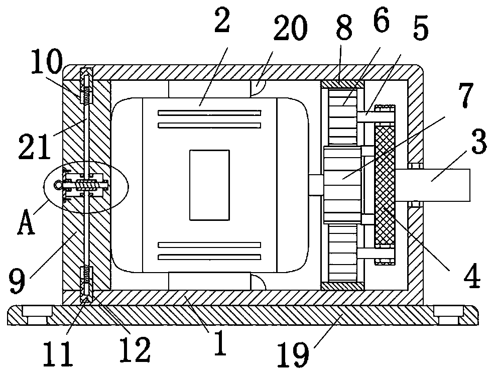
图1为本实用新型提出的一种直流行星齿轮减速电机的结构示意图;Fig. 1 is the structural representation of a kind of DC planetary gear reduction motor proposed by the utility model;
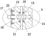
图2为本实用新型提出的一种直流行星齿轮减速电机的A部分的结构示意图。FIG. 2 is a schematic structural diagram of part A of a DC planetary gear reduction motor proposed by the utility model.
图中:1、壳体;2、电机;3、总输出轴;4、连接盘;5、连接轴;6、行星齿轮;7、太阳轮;8、内齿轮;9、盖板;10、竖向槽;11、卡接板;12、卡接槽;13、横向槽;14、蜗杆;15、凹槽;16、隔板;17、把手;18、轴套;19、底座;20、限位板;21、螺杆;22、蜗轮;23、套筒。In the figure: 1. Shell; 2. Motor; 3. Total output shaft; 4. Connecting plate; 5. Connecting shaft; 6. Planetary gear; 7. Sun gear; 8. Internal gear; 9. Cover plate; 10. Vertical slot; 11, clip plate; 12, clip slot; 13, horizontal slot; 14, worm; 15, groove; 16, partition plate; 17, handle; 18, shaft sleeve; 19, base; 20, Limit plate; 21, screw; 22, worm gear; 23, sleeve.
具体实施方式Detailed ways
下面将结合本实用新型实施例中的附图,对本实用新型实施例中的技术方案进行清楚、完整地描述,显然,所描述的实施例仅仅是本实用新型一部分实施例,而不是全部的实施例。The technical solutions in the embodiments of the present utility model will be clearly and completely described below with reference to the accompanying drawings in the embodiments of the present utility model. Obviously, the described embodiments are only a part of the embodiments of the present utility model, rather than all the implementations. example.
参照图1-2,一种直流行星齿轮减速电机,包括壳体1,壳体1一侧开设有安装孔,安装孔内转动安装有总输出轴3,总输出轴3位于壳体1内部的一端固定安装有连接盘4,连接盘4一侧开设有六个圆形孔,六个圆形孔呈环形等间距设置,六个圆形孔内均转动安装有连接轴5,壳体1内固定安装有内齿轮8并放置有电机2,六个连接轴5靠近电机2的一端均固定安装有行星齿轮6,六个行星齿轮6均与内齿轮8相啮合,电机2输出轴上固定安装有太阳轮7,六个行星齿轮6均与太阳轮7相啮合,壳体1的另一侧为开口设置并活动安装有盖板9,盖板9与电机2活动连接,盖板9顶部和底部均开设有竖向槽10,四个竖向槽10内均滑动安装有卡接板11,壳体1的顶部内壁和底部内壁上均开设有卡接槽12,两个卡接板11均与对应的卡接槽12活动卡装,两个卡接板11相互靠近的一侧均开设有螺纹孔,两个螺纹孔内螺纹安装有同一个螺杆21,螺杆21外侧顶端和底端分别设置有两个旋向相反的外螺纹,盖板9转动套设在螺杆21外侧,盖板9远离电机2的一侧开设有凹槽15,凹槽15一侧内壁上开设有横向槽13,横向槽13内转动安装有蜗杆14,螺杆21上固定安装有蜗轮22,蜗杆14与蜗轮22相啮合,蜗杆14外侧转动套设有隔板16,隔板16通过螺栓与凹槽15固定连接。Referring to Figure 1-2, a DC planetary gear reduction motor includes a
本实用新型中,蜗杆14远离电机2的一端固定安装有把手17,把手17设置为环形,方便控制蜗杆14的转动。In the present invention, a
本实用新型中,蜗杆14外侧固定套设有套筒23,套筒23与隔板16活动连接,对蜗杆14进行限位。In the present invention, a
本实用新型中,壳体1顶部内壁和底部内壁上均固定安装有限位板20,两个限位板20均与电机2活动连接,对电机2进行定位。In the present invention,
本实用新型中,螺杆21外侧固定套设有两个轴套18,两个轴套18分别与横向槽13顶部内壁和底部内壁滑动连接,对螺杆21进行限位。In the present invention, the outer fixed sleeve of the
本实用新型中,壳体1底部固定安装有底座19,底座19顶部四角均开设有螺纹安装孔,方便对装置进行安装。In the present invention, a
本实用新型中,在使用时,电机2输出轴带动太阳轮7转动,太阳轮7带动行星齿轮6转动,行星齿轮6通过与内齿轮8的啮合带动连接盘4和总输出轴3转动,从而实现减速增扭的效果,当需要对传动部件进行补充润滑油等维护工作时,通过控制把手17带动蜗杆14转动,蜗杆14带轮蜗轮22转动,蜗轮22带动螺杆21转动,螺杆21通过与两个卡接板11的螺纹配合带动两个卡接板11向相互靠近的一侧从而脱离对应的卡接槽12,然后拉动把手17取出盖板9并取出电机2,并进行补充润滑油等维护工作,维护结束后,放回电机2和盖板9,电机2在盖板9和两个限位板20的配合下进行固定,然后转动把手17带动两个卡接板11卡入对应的卡接槽12,从而对盖板9进行固定。In the utility model, when in use, the output shaft of the
Claims (6)
Priority Applications (1)
| Application Number | Priority Date | Filing Date | Title |
|---|---|---|---|
| CN202020119640.5U CN211429108U (en) | 2020-01-19 | 2020-01-19 | A DC planetary gear motor |
Applications Claiming Priority (1)
| Application Number | Priority Date | Filing Date | Title |
|---|---|---|---|
| CN202020119640.5U CN211429108U (en) | 2020-01-19 | 2020-01-19 | A DC planetary gear motor |
Publications (1)
| Publication Number | Publication Date |
|---|---|
| CN211429108U true CN211429108U (en) | 2020-09-04 |
Family
ID=72287295
Family Applications (1)
| Application Number | Title | Priority Date | Filing Date |
|---|---|---|---|
| CN202020119640.5U Expired - Fee Related CN211429108U (en) | 2020-01-19 | 2020-01-19 | A DC planetary gear motor |
Country Status (1)
| Country | Link |
|---|---|
| CN (1) | CN211429108U (en) |
Cited By (1)
| Publication number | Priority date | Publication date | Assignee | Title |
|---|---|---|---|---|
| CN116066525A (en) * | 2023-03-22 | 2023-05-05 | 陕西神渭煤炭管道运输有限责任公司 | Star wheel speed reducer for coal slurry conveying |
-
2020
- 2020-01-19 CN CN202020119640.5U patent/CN211429108U/en not_active Expired - Fee Related
Cited By (2)
| Publication number | Priority date | Publication date | Assignee | Title |
|---|---|---|---|---|
| CN116066525A (en) * | 2023-03-22 | 2023-05-05 | 陕西神渭煤炭管道运输有限责任公司 | Star wheel speed reducer for coal slurry conveying |
| CN116066525B (en) * | 2023-03-22 | 2023-06-27 | 陕西神渭煤炭管道运输有限责任公司 | Star wheel speed reducer for coal slurry conveying |
Similar Documents
| Publication | Publication Date | Title |
|---|---|---|
| CN209943485U (en) | A low energy consumption wind turbine yaw reducer | |
| CN203585256U (en) | Planetary differential speed reducer for crane | |
| CN204664310U (en) | Multipurpose power transmission system | |
| CN209324945U (en) | A drying rack reducer | |
| CN215148858U (en) | Clamping and fastening device for assembling gear box | |
| CN210919983U (en) | Robot joint power module | |
| CN110661371A (en) | Semi-direct drive planetary electric drum | |
| CN201772023U (en) | Fully sealed worm gear reducer | |
| CN209994233U (en) | Output stage gear can cut off power supply and rotate 360 degrees's gear motor | |
| CN218031283U (en) | Gear speed reducer for automobile pedal | |
| CN218598740U (en) | Motor speed reducing mechanism | |
| CN209671531U (en) | A planetary gear reducer | |
| CN201381093Y (en) | Two-tooth difference air cooling type electric roller | |
| CN205423790U (en) | Speed reducer | |
| CN216078151U (en) | Single-stage planetary reducer with large speed ratio and high torque | |
| CN216343711U (en) | A robot joint deceleration mechanism based on planetary gear train | |
| CN211875060U (en) | A hollow rotating platform | |
| CN207514669U (en) | A kind of two degrees of freedom headlamp | |
| CN213094008U (en) | Bidirectional output miniature gear reduction motor | |
| CN220687985U (en) | Spiral bevel gear reducer | |
| CN218953936U (en) | Reduction gearbox structure | |
| CN219994337U (en) | A reducer for permanent magnet synchronous motor coupling | |
| CN216078222U (en) | Speed reducing motor | |
| CN221462849U (en) | XD50 type double-stage worm gear reducer | |
| CN219918622U (en) | a low speed motor |
Legal Events
| Date | Code | Title | Description |
|---|---|---|---|
| GR01 | Patent grant | ||
| GR01 | Patent grant | ||
| CF01 | Termination of patent right due to non-payment of annual fee | ||
| CF01 | Termination of patent right due to non-payment of annual fee |
Granted publication date: 20200904 |