CN211413277U - Slotting equipment for processing metal doors and windows - Google Patents
Slotting equipment for processing metal doors and windows Download PDFInfo
- Publication number
- CN211413277U CN211413277U CN201922157372.6U CN201922157372U CN211413277U CN 211413277 U CN211413277 U CN 211413277U CN 201922157372 U CN201922157372 U CN 201922157372U CN 211413277 U CN211413277 U CN 211413277U
- Authority
- CN
- China
- Prior art keywords
- fixedly connected
- push
- push plate
- plate
- rod
- Prior art date
- Legal status (The legal status is an assumption and is not a legal conclusion. Google has not performed a legal analysis and makes no representation as to the accuracy of the status listed.)
- Expired - Fee Related
Links
- 239000002184 metal Substances 0.000 title claims abstract description 20
- 238000009434 installation Methods 0.000 claims abstract description 7
- 238000003754 machining Methods 0.000 claims 5
- 125000003003 spiro group Chemical group 0.000 claims 1
- 238000004519 manufacturing process Methods 0.000 abstract description 5
- 238000012423 maintenance Methods 0.000 abstract description 3
- 238000004080 punching Methods 0.000 description 3
- 238000005260 corrosion Methods 0.000 description 2
- 238000005516 engineering process Methods 0.000 description 2
- 239000000463 material Substances 0.000 description 2
- 238000000034 method Methods 0.000 description 2
- 229910001220 stainless steel Inorganic materials 0.000 description 2
- 239000010935 stainless steel Substances 0.000 description 2
- 229910000831 Steel Inorganic materials 0.000 description 1
- 230000003213 activating effect Effects 0.000 description 1
- 230000009286 beneficial effect Effects 0.000 description 1
- 230000007797 corrosion Effects 0.000 description 1
- 238000010586 diagram Methods 0.000 description 1
- 238000009413 insulation Methods 0.000 description 1
- 239000002932 luster Substances 0.000 description 1
- 230000004048 modification Effects 0.000 description 1
- 238000012986 modification Methods 0.000 description 1
- 229910001256 stainless steel alloy Inorganic materials 0.000 description 1
- 239000010959 steel Substances 0.000 description 1
Images
Landscapes
- Straightening Metal Sheet-Like Bodies (AREA)
Abstract
Description
技术领域technical field
本实用新型属于门窗加工技术领域,具体涉及一种金属门窗加工用开槽设备。The utility model belongs to the technical field of door and window processing, in particular to a slotting device for processing metal doors and windows.
背景技术Background technique
金属门窗一般都由不锈钢合金制作,要求金属门窗用不锈钢需要有极强的防腐性能且独具不锈钢的光泽,保温性能需要优于同结构普通钢,随着金属门窗使用的日益广泛,对不锈钢的技术要求也不断提高,需要其有足够的横向屈服强度和抗腐蚀性能。目前,门窗金属配件加工设备在流水线上实时操作时,存在:设备尺寸大、现场工人劳动强度大、工作效率低,需要数名、数十名等现场操作工人在不同的设备前同步作业,人员调配或者管理上存在较大的不方便;另外,现场作业时,尤其是对于冲孔、冲槽、截断等操作时,还存在安全隐患。虽然,研究人员也提出了一些自动化控制设备,然而,这类控制设备价格昂贵、功能不全,另外故障率较高。Metal doors and windows are generally made of stainless steel alloys. Stainless steel for metal doors and windows is required to have strong anti-corrosion performance and unique stainless steel luster. The thermal insulation performance needs to be better than ordinary steel of the same structure. The technical requirements are also constantly improving, and they need to have sufficient transverse yield strength and corrosion resistance. At present, when the door and window metal fittings processing equipment is operated in real time on the assembly line, there are: large equipment size, high labor intensity of on-site workers, low work efficiency, and the need for several or dozens of on-site operators to work synchronously in front of different equipment, and personnel There is a great inconvenience in deployment or management; in addition, there are potential safety hazards during on-site operations, especially for operations such as punching, grooving, and truncation. Although researchers have also proposed some automatic control devices, however, such control devices are expensive, ineffective, and have a high failure rate.
中国专利公开了一种金属门窗开槽打孔设备,申请号为 (201721240170.2),该专利技术能够保证其打孔或开槽的质量和精度,但是,该装置在使用的时候零件之间的结构复杂,在装置上的零件使用一定时间,发生损坏的时候人们难以对其进行维修,导致人们对装置的维修和保养会耽误大量的时间,从而降低了装置生产的时间和效率。The Chinese patent discloses a metal door and window slotting and punching equipment, the application number is (201721240170.2), the patented technology can ensure the quality and precision of its punching or slotting, but the structure between the parts when the device is used. It is complicated, the parts on the device are used for a certain period of time, and it is difficult for people to repair them when they are damaged, which leads to a lot of time delay in the repair and maintenance of the device, thus reducing the production time and efficiency of the device.
因此,本领域技术人员提供了一种金属门窗加工用开槽设备,以解决上述背景技术中提出的问题。Therefore, those skilled in the art provide a slotting equipment for processing metal doors and windows to solve the above-mentioned problems in the background art.
实用新型内容Utility model content
本实用新型的目的在于提供一种金属门窗加工用开槽设备,以解决上述背景技术中提出的问题。The purpose of the present invention is to provide a slotting device for processing metal doors and windows, so as to solve the problems raised in the above-mentioned background technology.
为实现上述目的,本实用新型提供如下技术方案:一种金属门窗加工用开槽设备,包括工作台、推动螺杆、推板和伸缩杆,所述工作台顶部固定连接有两个对称分布的支撑板,所述推动螺杆与所述支撑板转动连接,所述推动螺杆靠近所述推板的一端螺接固定有两个对称分布的限位螺杆,所述推动螺杆与所述推板转动连接,所述限位螺杆与所述推板接触,所述推板顶部外壁固定连接有滑轨,所述滑轨内滑动连接有支撑杆,所述推板底部外壁固定连接有卡合板,所述伸缩杆一端与所述支撑板固定连接,另一端固定连接有连接板,所述连接板上设有第二连接螺栓,所述连接板通过所述第二连接螺栓与所述推板螺接固定,所述支撑杆远离所述推板的一端可拆卸连接有安装杆,所述安装杆远离所述支撑杆的一端固定连接有气缸,所述气缸与外部气源连接,所述气缸输出端可拆卸连接有冲头,所述气缸位于所述工作台正上方。In order to achieve the above purpose, the utility model provides the following technical solutions: a slotting device for processing metal doors and windows, comprising a workbench, a push screw, a push plate and a telescopic rod, and the top of the workbench is fixedly connected with two symmetrically distributed supports plate, the push screw is rotatably connected with the support plate, two symmetrically distributed limit screws are screwed and fixed at one end of the push screw close to the push plate, the push screw is rotatably connected with the push plate, The limit screw is in contact with the push plate, the top outer wall of the push plate is fixedly connected with a slide rail, the slide rail is slidably connected with a support rod, the bottom outer wall of the push plate is fixedly connected with a snap plate, and the telescopic One end of the rod is fixedly connected with the support plate, and the other end is fixedly connected with a connecting plate, the connecting plate is provided with a second connecting bolt, and the connecting plate is screwed and fixed with the push plate through the second connecting bolt, One end of the support rod away from the push plate is detachably connected with a mounting rod, and one end of the mounting rod away from the support rod is fixedly connected with a cylinder, the cylinder is connected to an external air source, and the output end of the cylinder is detachable A punch is connected, and the cylinder is located just above the table.
优选的,所述工作台底部固定连接有四个对称分布的支腿,所述支腿底部固定连接有橡胶缓冲垫。Preferably, four symmetrically distributed legs are fixedly connected to the bottom of the workbench, and rubber buffer pads are fixedly connected to the bottom of the legs.
优选的,所述推动螺杆远离所述推板的一端设有转把,所述转把与所述推动螺杆固定连接。Preferably, a turning handle is provided at one end of the pushing screw rod away from the pushing plate, and the turning handle is fixedly connected with the pushing screw rod.
优选的,所述滑轨两端设有挡板,所述挡板与所述推板可拆卸连接,所述挡板上设有第一连接螺栓,所述挡板通过所述第一连接螺栓与所述推板螺接固定。Preferably, two ends of the slide rail are provided with baffles, the baffles are detachably connected to the push plate, and the baffles are provided with first connecting bolts, and the baffles pass through the first connecting bolts It is screwed and fixed with the push plate.
优选的,所述卡合板远离所述推板的一面固定连接有摩擦层,所述摩擦层的材质为橡胶。Preferably, a friction layer is fixedly connected to the side of the engaging plate away from the push plate, and the material of the friction layer is rubber.
优选的,所述安装杆上设有固定螺栓,所述安装杆通过所述固定螺栓与所述支撑杆螺接固定,所述冲头靠近所述气缸的一端固定连接有连接螺杆,所述冲头通过所述连接螺杆与所述气缸输出端螺接固定。Preferably, the mounting rod is provided with a fixing bolt, the mounting rod is screwed and fixed with the support rod through the fixing bolt, and a connecting screw is fixedly connected to one end of the punch close to the cylinder, and the punch is The head is screwed and fixed with the output end of the cylinder through the connecting screw.
与现有技术相比,本实用新型的有益效果是:本实用新型中推动螺杆可以和支撑板进行安装与拆卸,推板能够与推动螺杆进行安装与拆卸,气缸上的安装杆能够与支撑杆进行安装与拆卸,结构简单,可以在装置零件受到损坏的时候,对损坏的零件进行拆卸和更换,便于人们对装置的维修和保养,减少了维修装置的时间,相对的增加了装置可持续生产的时间,提高了装置的生产效率。Compared with the prior art, the beneficial effects of the present utility model are: in the present utility model, the push screw rod can be installed and disassembled with the support plate, the push plate can be installed and disassembled with the push screw rod, and the installation rod on the cylinder can be installed and disassembled with the support rod. It has a simple structure for installation and disassembly. When the parts of the device are damaged, the damaged parts can be disassembled and replaced, which is convenient for people to repair and maintain the device, reduces the time for repairing the device, and relatively increases the sustainable production of the device. time and improve the production efficiency of the device.
附图说明Description of drawings
附图用来提供对本实用新型的进一步理解,并且构成说明书的一部分,与本实用新型的实施例一起用于解释本实用新型,并不构成对本实用新型的限制。在附图中:The accompanying drawings are used to provide a further understanding of the present invention, and constitute a part of the specification, and are used to explain the present invention together with the embodiments of the present invention, and do not constitute a limitation to the present invention. In the attached image:
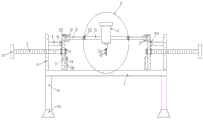
图1为本实用新型的结构示意图;Fig. 1 is the structural representation of the utility model;
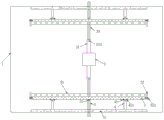
图2为本实用新型的俯视图;Fig. 2 is the top view of the utility model;
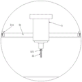
图3为本实用新型中A部的放大图;Fig. 3 is the enlarged view of A part in the utility model;
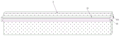
图4为本实用新型中推板的结构示意图。FIG. 4 is a schematic structural diagram of a push plate in the present invention.
图中:1、工作台;11、支撑板;12、支腿;121、橡胶缓冲垫; 2、推动螺杆;21、转把;22、限位螺杆;3、推板;31、滑轨;32、挡板;321、第一连接螺栓;33、支撑杆;34、卡合板;341、摩擦层; 4、伸缩杆;41、连接板;411、第二连接螺栓;5、气缸;51、安装杆;511、固定螺栓;52、冲头;521、连接螺杆。In the figure: 1. Workbench; 11. Supporting plate; 12. Outriggers; 121. Rubber cushion; 2. Pushing screw; 21. Turning handle; 22. Limit screw; 3. Pushing plate; 31. Slide rail; 32, baffle; 321, first connecting bolt; 33, support rod; 34, snap plate; 341, friction layer; 4, telescopic rod; 41, connecting plate; 411, second connecting bolt; 5, cylinder; 51, Mounting rod; 511, fixing bolt; 52, punch; 521, connecting screw.
具体实施方式Detailed ways
下面将结合本实用新型实施例中的附图,对本实用新型实施例中的技术方案进行清楚、完整地描述,显然,所描述的实施例仅仅是本实用新型一部分实施例,而不是全部的实施例。基于本实用新型中的实施例,本领域普通技术人员在没有做出创造性劳动前提下所获得的所有其他实施例,都属于本实用新型保护的范围。The technical solutions in the embodiments of the present utility model will be clearly and completely described below with reference to the accompanying drawings in the embodiments of the present utility model. Obviously, the described embodiments are only a part of the embodiments of the present utility model, rather than all the implementations. example. Based on the embodiments of the present invention, all other embodiments obtained by those of ordinary skill in the art without creative work fall within the protection scope of the present invention.
请参阅图1-4,本实用新型提供以下技术方案:一种金属门窗加工用开槽设备,包括工作台1、推动螺杆2、推板3和伸缩杆4,工作台1顶部固定连接有两个对称分布的支撑板11,推动螺杆2与支撑板11转动连接,推动螺杆2靠近推板3的一端螺接固定有两个对称分布的限位螺杆22,推动螺杆2与推板3转动连接,限位螺杆22 与推板3接触,推板3顶部外壁固定连接有滑轨31,滑轨31内滑动连接有支撑杆33,推板3底部外壁固定连接有卡合板34,伸缩杆4 一端与支撑板11固定连接,另一端固定连接有连接板41,连接板41 上设有第二连接螺栓411,连接板41通过第二连接螺栓411与推板3 螺接固定,支撑杆33远离推板3的一端可拆卸连接有安装杆51,安装杆51远离支撑杆33的一端固定连接有气缸5,气缸5与外部气源连接,气缸5输出端可拆卸连接有冲头52,气缸5位于工作台1正上方。1-4, the present utility model provides the following technical solutions: a slotting equipment for processing metal doors and windows, comprising a
本实施方案中:包括工作台1、推动螺杆2、推板3和伸缩杆4,工作台1顶部固定连接有两个对称分布的支撑板11,推动螺杆2与支撑板11转动连接,推动螺杆2靠近推板3的一端螺接固定有两个对称分布的限位螺杆22,推动螺杆2与推板3转动连接,限位螺杆 22与推板3接触,通过限位螺杆22可以对推板3起到一个固定的作用,然后让推动螺杆2与支撑板11之间转动,以此来带动推板3向前或向后移动,这时候限位螺杆22会随着推动螺杆2一起转动,而且能够把推板3固定在两个限位螺杆22之间,推板3顶部外壁固定连接有滑轨31,滑轨31内滑动连接有支撑杆33,推板3底部外壁固定连接有卡合板34,在推动螺杆2带动推板3相对移动的时候,推板3可以通过卡合板34来对需要开槽的门窗进行固定,伸缩杆4一端与支撑板11固定连接,另一端固定连接有连接板41,连接板41 上设有第二连接螺栓411,连接板41通过第二连接螺栓411与推板3 螺接固定,支撑杆33远离推板3的一端可拆卸连接有安装杆51,安装杆51远离支撑杆33的一端固定连接有气缸5,气缸5与外部气源连接,气缸5输出端可拆卸连接有冲头52,气缸5位于工作台1正上方,气缸5的型号为SC60,在需要调节气缸5的位置的时候可以让支撑杆33在滑轨31中滑动,从而通过安装杆51带动带动气缸5 移动,当卡合板34卡合住门窗的时候,可以把安装杆51在支撑杆 33上移动,从而带动气缸5的移动,从而对气缸5的位置进行调整,当调整到合适的位置,再启动气缸5就能够对金属门窗进行冲槽。In this embodiment, it includes a
在图1中:工作台1底部固定连接有四个对称分布的支腿12,支腿12底部固定连接有橡胶缓冲垫121;通过支腿12可以对工作台 1进行支撑,然后通过橡胶缓冲垫121能够在冲槽的时候减缓支腿12 与地面之间的振动。In Figure 1: the bottom of the
在图1中:推动螺杆2远离推板3的一端设有转把21,转把21 与推动螺杆2固定连接;人们在转动推动螺杆2的时候,可以握住转把21,推动推板3向前移动的时候,握住转把21便于人们的操作。In Fig. 1: the end of the
在图4中:滑轨31两端设有挡板32,挡板32与推板3可拆卸连接,挡板32上设有第一连接螺栓321,挡板32通过第一连接螺栓 321与推板3螺接固定;通过挡板32能够在人们控制支撑杆33在滑轨31内滑动的时候通过挡板32可以防止支撑杆33滑落出滑轨31。In FIG. 4 : baffles 32 are provided at both ends of the
在图1中:卡合板34远离推板3的一面固定连接有摩擦层341,摩擦层341的材质为橡胶;通过摩擦层341可以在卡合板34对需要加工的门窗进行卡合的时候来增加卡合板34与金属门窗之间的摩擦力,防止门窗发生脱落的现象。In FIG. 1 : a
在图3中:安装杆51上设有固定螺栓511,安装杆51通过固定螺栓511与支撑杆33螺接固定,冲头52靠近气缸5的一端固定连接有连接螺杆521,冲头52通过连接螺杆521与气缸5输出端螺接固定;能够在支撑杆33上选取合适的螺纹安装孔,然后通过固定螺栓 511穿过安装杆51来与支撑杆33上的安装杆51进行螺接固定,能够选取不同规格的冲头52通过连接螺杆521旋入气缸5的输出端来与气缸5进行安装与拆卸。In Fig. 3: the mounting
本实用新型的工作原理及使用流程:在使用本装置的时候,让推动螺杆2和支撑板11转动,以此来带动推板3向前或向后移动,这时候限位螺杆22会随着推动螺杆2一起转动,能够把推板3固定在两个限位螺杆22之间,从而带动推板3相对移动,推板3可以通过卡合板34来对需要开槽的门窗进行固定,在需要调节气缸5的位置的时候可以让支撑杆33在滑轨31中滑动,从而通过安装杆51带动带动气缸5移动,当卡合板34卡合住门窗的时候,可以把安装杆51 在支撑杆33上移动,从而带动气缸5的移动,从而对气缸5的位置进行调整,当调整到合适的位置,再启动气缸5就能够对金属门窗进行冲槽。The working principle and use process of the present utility model: when the device is used, the
最后应说明的是:以上所述仅为本实用新型的优选实施例而已,并不用于限制本实用新型,尽管参照前述实施例对本实用新型进行了详细的说明,对于本领域的技术人员来说,其依然可以对前述各实施例所记载的技术方案进行修改,或者对其中部分技术特征进行等同替换。凡在本实用新型的精神和原则之内,所作的任何修改、等同替换、改进等,均应包含在本实用新型的保护范围之内。Finally, it should be noted that the above are only the preferred embodiments of the present invention, and are not intended to limit the present invention. , it is still possible to modify the technical solutions described in the foregoing embodiments, or perform equivalent replacements to some of the technical features. Any modification, equivalent replacement, improvement, etc. made within the spirit and principle of the present invention shall be included in the protection scope of the present invention.
Claims (6)
Priority Applications (1)
| Application Number | Priority Date | Filing Date | Title |
|---|---|---|---|
| CN201922157372.6U CN211413277U (en) | 2019-12-05 | 2019-12-05 | Slotting equipment for processing metal doors and windows |
Applications Claiming Priority (1)
| Application Number | Priority Date | Filing Date | Title |
|---|---|---|---|
| CN201922157372.6U CN211413277U (en) | 2019-12-05 | 2019-12-05 | Slotting equipment for processing metal doors and windows |
Publications (1)
| Publication Number | Publication Date |
|---|---|
| CN211413277U true CN211413277U (en) | 2020-09-04 |
Family
ID=72286859
Family Applications (1)
| Application Number | Title | Priority Date | Filing Date |
|---|---|---|---|
| CN201922157372.6U Expired - Fee Related CN211413277U (en) | 2019-12-05 | 2019-12-05 | Slotting equipment for processing metal doors and windows |
Country Status (1)
| Country | Link |
|---|---|
| CN (1) | CN211413277U (en) |
-
2019
- 2019-12-05 CN CN201922157372.6U patent/CN211413277U/en not_active Expired - Fee Related
Similar Documents
| Publication | Publication Date | Title |
|---|---|---|
| CN107042418B (en) | Clamping device for machining | |
| CN213856538U (en) | Stamping equipment convenient to dismouting | |
| CN204339018U (en) | A support device used on a CNC hydraulic pendulum shearing machine | |
| CN211072348U (en) | Welding device for sheet metal parts | |
| CN217452639U (en) | Laser cutting mechanism walking structure | |
| CN205600259U (en) | Quick locking mechanism of screw | |
| CN203831037U (en) | Disassembling tool for impeller of draught fan | |
| CN222326316U (en) | A bending device for processing aluminum alloy doors and windows | |
| CN211028184U (en) | Punching positioning mechanism for metal door and window processing | |
| CN211541867U (en) | A kind of plate round hole drilling bit | |
| CN204262360U (en) | The manufacture of cement wearing and tearing spindle nose of roller machine roll shaft repairs frock | |
| CN204235501U (en) | A kind of blower fan water-cooling system triple valve replacing frock | |
| CN209491752U (en) | A kind of erection support of electric power overhaul robot | |
| CN219151718U (en) | pipe cutting jig | |
| CN106826057B (en) | A kind of T-shaped workpiece centralising device | |
| CN204565881U (en) | A kind of polishing carrier | |
| CN209157811U (en) | A Servo ATC Tool Transmission System for Vertical Lathe | |
| CN208913426U (en) | Door frame welding device of civil air defense equipment | |
| CN220868873U (en) | Swift formula jib installation device | |
| CN218796830U (en) | Lengthening rod device for spray gun | |
| CN218668657U (en) | Safety belt suspension clamp capable of being freely adjusted in high-altitude operation | |
| CN218226346U (en) | Assembling tool for high-sealing radiator | |
| CN212734383U (en) | High-efficient plate shearing machine | |
| CN110805291A (en) | PC building wallboard reserves sleeve pipe joint bar positioner | |
| CN204059998U (en) | Hanging-connecting crab-bolt hydraulic pusher |
Legal Events
| Date | Code | Title | Description |
|---|---|---|---|
| GR01 | Patent grant | ||
| GR01 | Patent grant | ||
| CF01 | Termination of patent right due to non-payment of annual fee |
Granted publication date: 20200904 |
|
| CF01 | Termination of patent right due to non-payment of annual fee |