CN211405255U - A traveling device for transmission line detection - Google Patents
A traveling device for transmission line detection Download PDFInfo
- Publication number
- CN211405255U CN211405255U CN201921910893.8U CN201921910893U CN211405255U CN 211405255 U CN211405255 U CN 211405255U CN 201921910893 U CN201921910893 U CN 201921910893U CN 211405255 U CN211405255 U CN 211405255U
- Authority
- CN
- China
- Prior art keywords
- traveling device
- fixedly connected
- transmission line
- rotating column
- line detection
- Prior art date
- Legal status (The legal status is an assumption and is not a legal conclusion. Google has not performed a legal analysis and makes no representation as to the accuracy of the status listed.)
- Expired - Fee Related
Links
Images


Landscapes
- Gear Transmission (AREA)
Abstract
本实用新型公开了一种输电线路检测用行走装置,包括行走装置,所述行走装置的顶部设置有电线,所述电线的两侧均电性连接有电线杆,所述行走装置的顶部与电线滑动连接,所述行走装置的右侧固定连接有托盘,所述托盘的顶部固定连接有微型气缸。本实用新型通过托盘、微型气缸、齿板、轴承、转杆、齿轮一、转柱、齿轮二、连接块和摄像头的配合使用,通过转柱旋转带动连接块和摄像头旋转,达到可以调节摄像头角度的效果,该输电线路检测用行走装置,解决了现有的巡检行走装置上的巡检摄像头只能拍摄同一条水平线上的画面,无法拍摄其他的方位角度,导致巡检的准确度大大降低的问题,增强了巡检行走装置的实用性,便于使用者使用。
The utility model discloses a traveling device for power transmission line detection, comprising a traveling device, an electric wire is arranged on the top of the traveling device, electric poles are electrically connected on both sides of the electric wire, and the top of the traveling device is connected to the electric wire. sliding connection, a tray is fixedly connected to the right side of the walking device, and a micro cylinder is fixedly connected to the top of the tray. The utility model uses the tray, the micro cylinder, the tooth plate, the bearing, the rotating rod, the first gear, the rotating column, the second gear, the connecting block and the camera to rotate, and the rotating column drives the connecting block and the camera to rotate, so that the angle of the camera can be adjusted. The traveling device for power transmission line detection solves the problem that the inspection camera on the existing inspection traveling device can only take pictures on the same horizontal line, and cannot take other azimuth angles, which greatly reduces the accuracy of inspection. It enhances the practicability of the inspection walking device and is convenient for users to use.
Description
技术领域technical field
本实用新型涉及输电线路技术领域,具体为一种输电线路检测用行走装置。The utility model relates to the technical field of power transmission lines, in particular to a traveling device for power transmission line detection.
背景技术Background technique
输电线路是用变压器将发电机发出的电能升压后,再经断路器等控制设备接入输电线路来实现。结构形式,输电线路分为架空输电线路和电缆线路。The transmission line is realized by using a transformer to boost the power generated by the generator, and then connecting it to the transmission line through control equipment such as circuit breakers. In terms of structure, transmission lines are divided into overhead transmission lines and cable lines.
输电线路在检测时需要用到巡检行走装置,但现有的巡检行走装置上的巡检摄像头只能拍摄同一条水平线上的画面,无法拍摄其他的方位角度,导致巡检的准确度大大降低,降低了巡检行走装置的实用性,不便于使用者使用。The inspection traveling device needs to be used in the inspection of the transmission line, but the inspection camera on the existing inspection traveling device can only take pictures on the same horizontal line, and cannot take other azimuth angles, which leads to the great accuracy of inspection. The lowering reduces the practicability of the inspection walking device and is inconvenient for users to use.
实用新型内容Utility model content
本实用新型的目的在于提供一种输电线路检测用行走装置,具备可以调节摄像头角度的优点,解决了现有的巡检行走装置上的巡检摄像头只能拍摄同一条水平线上的画面,无法拍摄其他的方位角度,导致巡检的准确度大大降低的问题。The purpose of the utility model is to provide a traveling device for power transmission line detection, which has the advantage that the angle of the camera can be adjusted, and solves the problem that the inspection camera on the existing inspection traveling device can only shoot pictures on the same horizontal line, and cannot take pictures. Other azimuth angles lead to the problem that the accuracy of inspection is greatly reduced.
为实现上述目的,本实用新型提供如下技术方案:一种输电线路检测用行走装置,包括行走装置,所述行走装置的顶部设置有电线,所述电线的两侧均电性连接有电线杆,所述行走装置的顶部与电线滑动连接,所述行走装置的右侧固定连接有托盘,所述托盘的顶部固定连接有微型气缸,所述微型气缸的输出端固定连接有齿板,所述行走装置顶部的右侧固定连接有轴承,所述轴承的内部活动连接有转杆,所述转杆的表面套接有齿轮一,所述齿轮一的背面与齿板啮合,所述行走装置顶部的右侧且位于轴承的左侧贯穿设置有转柱,所述转柱的表面套接有齿轮二,所述齿轮二的右侧与齿轮一啮合,所述转柱的底部贯穿至行走装置的底部并固定连接有连接块,所述连接块的底部固定连接有摄像头,所述连接块顶部的两侧均固定连接有定位杆,所述定位杆的顶部与行走装置滑动连接。In order to achieve the above purpose, the present utility model provides the following technical solutions: a traveling device for power transmission line detection, comprising a traveling device, the top of the traveling device is provided with an electric wire, and both sides of the electric wire are electrically connected with utility poles, The top of the walking device is slidably connected with the wires, the right side of the walking device is fixedly connected with a tray, the top of the tray is fixedly connected with a micro cylinder, the output end of the micro cylinder is fixedly connected with a toothed plate, and the walking The right side of the top of the device is fixedly connected with a bearing, the inside of the bearing is movably connected with a rotating rod, the surface of the rotating rod is sleeved with a gear one, the back of the gear one is meshed with the tooth plate, and the top of the walking device is The right side and the left side of the bearing are provided with a rotating column, the surface of the rotating column is sleeved with the second gear, the right side of the second gear is meshed with the first gear, and the bottom of the rotating column penetrates to the bottom of the traveling device A connecting block is fixedly connected, a camera is fixedly connected to the bottom of the connecting block, a positioning rod is fixedly connected to both sides of the top of the connecting block, and the top of the positioning rod is slidably connected to the traveling device.
优选的,所述行走装置底部的右侧开设有圆形槽,所述定位杆的顶部滑动连接在圆形槽的内部。Preferably, a circular groove is provided on the right side of the bottom of the walking device, and the top of the positioning rod is slidably connected inside the circular groove.
优选的,所述转柱的顶部固定连接有挡板,所述挡板配合转柱使用。Preferably, a baffle is fixedly connected to the top of the rotating column, and the baffle is used in conjunction with the rotating column.
优选的,所述转柱的表面且位于行动装置的顶部套接有限位套,所述限位套的底部与行动装置固定连接。Preferably, the surface of the rotating column is located at the top of the mobile device and is sleeved with a limit sleeve, and the bottom of the limit sleeve is fixedly connected with the mobile device.
优选的,所述托盘的底部固定连接有斜块,所述斜块的左侧与行动装置固定连接。Preferably, an inclined block is fixedly connected to the bottom of the tray, and the left side of the inclined block is fixedly connected to the mobile device.
优选的,所述微型气缸的型号为AS2200-01。Preferably, the model of the micro cylinder is AS2200-01.
与现有技术相比,本实用新型的有益效果如下:Compared with the prior art, the beneficial effects of the present utility model are as follows:
1、本实用新型通过托盘、微型气缸、齿板、轴承、转杆、齿轮一、转柱、齿轮二、连接块和摄像头的配合使用,通过转柱旋转带动连接块和摄像头旋转,达到可以调节摄像头角度的效果,该输电线路检测用行走装置,解决了现有的巡检行走装置上的巡检摄像头只能拍摄同一条水平线上的画面,无法拍摄其他的方位角度,导致巡检的准确度大大降低的问题,增强了巡检行走装置的实用性,便于使用者使用。1. The utility model uses the cooperation of the tray, the miniature cylinder, the tooth plate, the bearing, the rotating rod, the first gear, the rotating column, the second gear, the connecting block and the camera, and drives the connecting block and the camera to rotate through the rotation of the rotating column. The effect of the camera angle, the traveling device for power transmission line detection, solves the problem that the inspection camera on the existing inspection traveling device can only shoot pictures on the same horizontal line, and cannot shoot other azimuth angles, resulting in the accuracy of the inspection. The problem is greatly reduced, the practicability of the inspection walking device is enhanced, and the user is convenient to use.
2、本实用新型通过圆形槽的设置,能够使定位杆更加流畅的在行动装置的底部滑动,减少了定位杆与行动装置之间的摩擦,延长了定位杆的使用寿命,同时对定位杆起到了限位的效果,通过挡板的设置,能够使转柱更加稳定的旋转,同时起到了限位的效果,通过限位套的设置,能够使转柱更加稳定的旋转,同时对转柱起到了限位的效果,防止转柱出现倾斜的现象,通过斜块的设置,能够使托盘更加稳定,防止托盘出现晃动的现象,同时对托盘起到了支撑的效果。2. The utility model can make the positioning rod slide more smoothly at the bottom of the mobile device through the setting of the circular groove, reduce the friction between the positioning rod and the mobile device, prolong the service life of the positioning rod, It has the effect of limiting the position. The setting of the baffle can make the rotating column rotate more stably, and at the same time, it has the effect of limiting the position. The setting of the limiting sleeve can make the rotating column rotate more stably. It has the effect of limiting the position and preventing the tilting of the rotating column. The setting of the inclined block can make the tray more stable, prevent the tray from shaking, and at the same time play a supporting effect on the tray.
附图说明Description of drawings
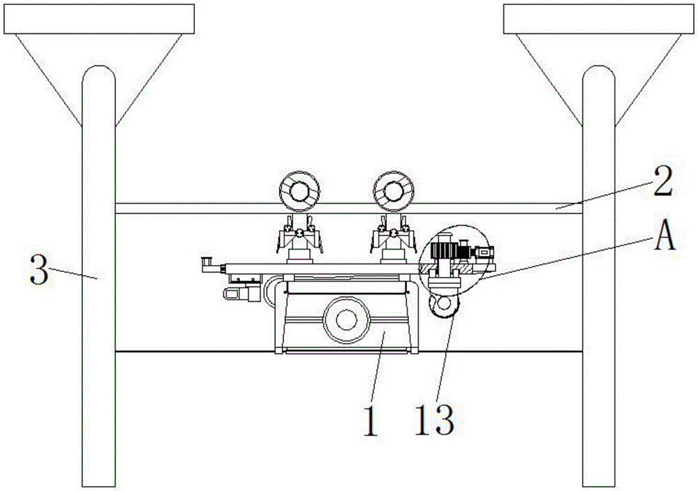
图1为本实用新型结构示意图;Fig. 1 is the structural representation of the utility model;
图2为本实用新型结构图1中A处放大结构图;Fig. 2 is the enlarged structure diagram of A place in the utility model structure Fig. 1;
图3为本实用新型局部结构侧视图。FIG. 3 is a side view of the partial structure of the utility model.
图中:1行走装置、2电线、3电线杆、4托盘、5微型气缸、6 齿板、7轴承、8转杆、9齿轮一、10转柱、11齿轮二、12连接块、 13摄像头、14定位杆、15圆形槽、16挡板、17限位套、18斜块。In the picture: 1 traveling device, 2 electric wires, 3 electric poles, 4 trays, 5 micro cylinders, 6 tooth plates, 7 bearings, 8 rotating rods, 9 gears one, 10 rotating columns, 11 gear two, 12 connecting blocks, 13 cameras , 14 positioning rods, 15 circular grooves, 16 baffles, 17 limit sleeves, 18 inclined blocks.
具体实施方式Detailed ways
下面将结合本实用新型实施例中的附图,对本实用新型实施例中的技术方案进行清楚、完整地描述,显然,所描述的实施例仅仅是本实用新型一部分实施例,而不是全部的实施例。基于本实用新型中的实施例,本领域普通技术人员在没有做出创造性劳动前提下所获得的所有其他实施例,都属于本实用新型保护的范围。The technical solutions in the embodiments of the present utility model will be clearly and completely described below with reference to the accompanying drawings in the embodiments of the present utility model. Obviously, the described embodiments are only a part of the embodiments of the present utility model, rather than all the implementations. example. Based on the embodiments of the present invention, all other embodiments obtained by those of ordinary skill in the art without creative work fall within the protection scope of the present invention.
请参阅图1-3,一种输电线路检测用行走装置,包括行走装置1,行走装置1底部的右侧开设有圆形槽15,定位杆14的顶部滑动连接在圆形槽15的内部,通过圆形槽15的设置,能够使定位杆14更加流畅的在行动装置1的底部滑动,减少了定位杆14与行动装置1之间的摩擦,延长了定位杆14的使用寿命,同时对定位杆14起到了限位的效果,行走装置1的顶部设置有电线2,电线2的两侧均电性连接有电线杆3,行走装置1的顶部与电线2滑动连接,行走装置1的右侧固定连接有托盘4,托盘4的底部固定连接有斜块18,斜块18 的左侧与行动装置1固定连接,通过斜块18的设置,能够使托盘4 更加稳定,防止托盘4出现晃动的现象,同时对托盘4起到了支撑的效果,托盘4的顶部固定连接有微型气缸5,微型气缸5的输出端固定连接有齿板6,行走装置1顶部的右侧固定连接有轴承7,轴承7 的内部活动连接有转杆8,转杆8的表面套接有齿轮一9,齿轮一9 的背面与齿板6啮合,行走装置1顶部的右侧且位于轴承7的左侧贯穿设置有转柱10,转柱10的顶部固定连接有挡板16,挡板16配合转柱10使用,通过挡板16的设置,能够使转柱10更加稳定的旋转,同时起到了限位的效果,转柱10的表面且位于行动装置1的顶部套接有限位套17,限位套17的底部与行动装置1固定连接,通过限位套17的设置,能够使转柱10更加稳定的旋转,同时对转柱10起到了限位的效果,防止转柱10出现倾斜的现象,转柱10的表面套接有齿轮二11,齿轮二11的右侧与齿轮一9啮合,转柱10的底部贯穿至行走装置1的底部并固定连接有连接块12,连接块12的底部固定连接有摄像头13,连接块12顶部的两侧均固定连接有定位杆14,定位杆14的顶部与行走装置1滑动连接。Please refer to Fig. 1-3, a traveling device for power transmission line detection, including a
使用时,首先使用者启动微型气缸5,微型气缸5的输出端带动齿板6左右移动,齿板6左右移动带动转杆8旋转,转杆8旋转带动齿轮一9旋转,齿轮一9旋转带动齿轮二11旋转,齿轮二11旋转带动转柱10旋转,转柱10旋转带动连接块12和摄像头13旋转,致使达到可以调节摄像头13角度的效果。When using, the user first starts the
综上所述:该输电线路检测用行走装置,通过托盘4、微型气缸 5、齿板6、轴承7、转杆8、齿轮一9、转柱10、齿轮二11、连接块 12和摄像头13的配合使用,通过转柱10旋转带动连接块12和摄像头13旋转,达到可以调节摄像头13角度的效果,该输电线路检测用行走装置,解决了现有的巡检行走装置上的巡检摄像头只能拍摄同一条水平线上的画面,无法拍摄其他的方位角度,导致巡检的准确度大大降低的问题。To sum up, the traveling device for power transmission line detection passes through the
尽管已经示出和描述了本实用新型的实施例,对于本领域的普通技术人员而言,可以理解在不脱离本实用新型的原理和精神的情况下可以对这些实施例进行多种变化、修改、替换和变型,本实用新型的范围由所附权利要求及其等同物限定。Although the embodiments of the present invention have been shown and described, it will be understood by those skilled in the art that various changes and modifications can be made to these embodiments without departing from the principles and spirit of the present invention , alternatives and modifications, the scope of the present invention is defined by the appended claims and their equivalents.
Claims (6)
Priority Applications (1)
| Application Number | Priority Date | Filing Date | Title |
|---|---|---|---|
| CN201921910893.8U CN211405255U (en) | 2019-11-07 | 2019-11-07 | A traveling device for transmission line detection |
Applications Claiming Priority (1)
| Application Number | Priority Date | Filing Date | Title |
|---|---|---|---|
| CN201921910893.8U CN211405255U (en) | 2019-11-07 | 2019-11-07 | A traveling device for transmission line detection |
Publications (1)
| Publication Number | Publication Date |
|---|---|
| CN211405255U true CN211405255U (en) | 2020-09-01 |
Family
ID=72213958
Family Applications (1)
| Application Number | Title | Priority Date | Filing Date |
|---|---|---|---|
| CN201921910893.8U Expired - Fee Related CN211405255U (en) | 2019-11-07 | 2019-11-07 | A traveling device for transmission line detection |
Country Status (1)
| Country | Link |
|---|---|
| CN (1) | CN211405255U (en) |
Cited By (3)
| Publication number | Priority date | Publication date | Assignee | Title |
|---|---|---|---|---|
| CN114002235A (en) * | 2021-10-29 | 2022-02-01 | 深圳供电局有限公司 | Visual scanning device for power transmission line detection |
| CN114228991A (en) * | 2021-12-24 | 2022-03-25 | 杭州申昊科技股份有限公司 | Transmission line inspection robot based on unmanned aerial vehicle |
| CN114261511A (en) * | 2021-12-24 | 2022-04-01 | 杭州申昊科技股份有限公司 | Power transmission line inspection robot |
-
2019
- 2019-11-07 CN CN201921910893.8U patent/CN211405255U/en not_active Expired - Fee Related
Cited By (3)
| Publication number | Priority date | Publication date | Assignee | Title |
|---|---|---|---|---|
| CN114002235A (en) * | 2021-10-29 | 2022-02-01 | 深圳供电局有限公司 | Visual scanning device for power transmission line detection |
| CN114228991A (en) * | 2021-12-24 | 2022-03-25 | 杭州申昊科技股份有限公司 | Transmission line inspection robot based on unmanned aerial vehicle |
| CN114261511A (en) * | 2021-12-24 | 2022-04-01 | 杭州申昊科技股份有限公司 | Power transmission line inspection robot |
Similar Documents
| Publication | Publication Date | Title |
|---|---|---|
| CN216113051U (en) | But many display device of chinese teaching of automatically regulated angle | |
| CN205336408U (en) | A portable electric panoramic shooting platform | |
| CN204667032U (en) | panoramic shooting device | |
| CN203313292U (en) | Camera and mobile device with same | |
| CN207319497U (en) | A kind of new teaching stop-motion animation shooting device | |
| CN218385925U (en) | Cable television transmission cable connection structure | |
| CN206861207U (en) | The filming apparatus of electrodynamic type adjustable-angle | |
| CN214064430U (en) | A multi-angle shooting camera for video capture | |
| WO2021056175A1 (en) | Cutting apparatus for metal cable processing | |
| CN205877624U (en) | A multifunctional camera shaft arm | |
| CN202979105U (en) | Rotatable and portable broadcast teleprompter | |
| CN206522587U (en) | A kind of image processing equipment support | |
| CN214543443U (en) | Protection device for internal circuit of junction box | |
| CN110822246A (en) | A visual display and exhibition system based on VR technology | |
| CN204678008U (en) | Omni-directional camera projection camera travel(l)ing rest | |
| CN209299405U (en) | A kind of video conference device | |
| CN212324244U (en) | Novel office video conference equipment | |
| CN206442440U (en) | A kind of video conference high-definition camera with movable camera | |
| CN220506266U (en) | Multi-angle remote sensing photographing device | |
| CN221723774U (en) | A cloud conference room camera bracket | |
| CN214190525U (en) | An easy-to-move dc waterproof cable placement rack | |
| CN2618192Y (en) | Portable terminal apparatus with image picker | |
| CN220271713U (en) | Animation generation device based on virtual digital person | |
| CN213585979U (en) | A hemispherical high-definition digital network camera | |
| CN206402304U (en) | A News Release System Based on Internet |
Legal Events
| Date | Code | Title | Description |
|---|---|---|---|
| GR01 | Patent grant | ||
| GR01 | Patent grant | ||
| TR01 | Transfer of patent right |
Effective date of registration: 20210129 Address after: 330000 traffic science and technology building, 249 Fuhe North Road, Donghu District, Nanchang City, Jiangxi Province Patentee after: Jiangxi port and Waterway Construction Investment Group Co.,Ltd. Address before: 312300 No.5, xujianong, Dongjiao Road, Shangyu City, Shaoxing City, Zhejiang Province Patentee before: Li Ying |
|
| TR01 | Transfer of patent right | ||
| CF01 | Termination of patent right due to non-payment of annual fee |
Granted publication date: 20200901 |
|
| CF01 | Termination of patent right due to non-payment of annual fee |