CN211393451U - Novel self-tightening brake - Google Patents
Novel self-tightening brake Download PDFInfo
- Publication number
- CN211393451U CN211393451U CN201922019229.0U CN201922019229U CN211393451U CN 211393451 U CN211393451 U CN 211393451U CN 201922019229 U CN201922019229 U CN 201922019229U CN 211393451 U CN211393451 U CN 211393451U
- Authority
- CN
- China
- Prior art keywords
- elevator
- voussoir
- car
- tightening
- wire rope
- Prior art date
- Legal status (The legal status is an assumption and is not a legal conclusion. Google has not performed a legal analysis and makes no representation as to the accuracy of the status listed.)
- Expired - Fee Related
Links
- 230000000694 effects Effects 0.000 claims abstract description 9
- 238000000034 method Methods 0.000 abstract description 6
- 229910000831 Steel Inorganic materials 0.000 description 16
- 239000010959 steel Substances 0.000 description 16
- 238000003825 pressing Methods 0.000 description 6
- 230000033001 locomotion Effects 0.000 description 5
- 230000009977 dual effect Effects 0.000 description 4
- 230000002265 prevention Effects 0.000 description 4
- 238000005516 engineering process Methods 0.000 description 2
- 238000007689 inspection Methods 0.000 description 2
- 230000004048 modification Effects 0.000 description 2
- 238000012986 modification Methods 0.000 description 2
- 230000001960 triggered effect Effects 0.000 description 2
- 238000005299 abrasion Methods 0.000 description 1
- 238000007792 addition Methods 0.000 description 1
- 230000001174 ascending effect Effects 0.000 description 1
- 230000009286 beneficial effect Effects 0.000 description 1
- 238000009434 installation Methods 0.000 description 1
- 239000007788 liquid Substances 0.000 description 1
- 230000007774 longterm Effects 0.000 description 1
- 230000001050 lubricating effect Effects 0.000 description 1
- 238000004519 manufacturing process Methods 0.000 description 1
- 238000005457 optimization Methods 0.000 description 1
Images



Landscapes
- Maintenance And Inspection Apparatuses For Elevators (AREA)
Abstract
The utility model relates to an elevator safety protection technique, more specifically the novel self-tightening formula stopper that says so, include counterweight block, wire rope, car, self-tightening device, fixed voussoir, activity voussoir, fixing base and driving sheave, counterweight block and car distribute at the both ends of driving sheave, be equipped with fixed voussoir and activity voussoir respectively to the wire rope periphery of counterweight block side and car side. A double safety brake for elevators can be provided.
Description
Technical Field
The utility model relates to an elevator safety protection technique, more specifically the novel self-clinching formula stopper that says so.
Background
Along with the continuous deepening of the urbanization process, the demand of the elevator is continuously enlarged, people use the elevator more and more frequently, and the safety of the elevator is also more emphasized. The rope clamping device is widely used for elevator safety protection such as ascending overspeed protection, car accidental movement prevention, brake failure prevention and the like, and gradually becomes a necessary safety component of an elevator. For safety, the common elevator rope clamping device adopts a power-off triggering mode, namely when the elevator is powered off, the rope clamping device can act immediately. The action of the rope clamp is often faster than that of the brake, so that the rope pressing plate presses the steel wire rope still in motion, and serious abrasion is caused to the rope pressing plate and the steel wire rope. Frequent and unnecessary actions tend to shorten the service life of the rope pressing plate and the steel wire rope, and the cost of the elevator in use is increased. In addition, when the rope clamping device is matched with the safety tongs to prevent the lift car from moving accidentally, the elevator is powered off, unnecessary actions of the safety tongs can be triggered, the elevator traction machine is a power driving device of the elevator, the traction machine is provided with a band-type brake device, and the band-type brake device has the function of stopping the rotation of the traction wheel through friction between the band-type brake device and the traction wheel when the elevator is required to stop. The traction sheave stops rotating to stop the operation of the elevator car. A band-type brake device is a very major elevator safety component. The elevator car is the equipment that high-rise building must possess, also is the basis of guaranteeing that elevator equipment carries from top to bottom, and its quality of use has important meaning to whole elevator operation safety. If the lift car has the problem of accidental movement in the process of operation, potential safety hazards can be brought to the operation of the lift, and even the lift car moves in a door opening state, so that the personal safety of passengers can be endangered. Based on this, the protection device and the inspection method for the accidental movement of the elevator car are mainly researched.
The elevator type test regulation (TSGT7007-2016) and GB7588-2003 Elevator manufacturing and installation safety Specification No. 1 modification notes approved and released by the State quality inspection administration are particularly described
At present, a rope clamping device is commonly arranged at the lower end of a machine room tractor. Whether the elevator car moves accidentally or not is detected through the elevator. Therefore, the control system and the electric switch enable the rope clamp to act, and simultaneously clamp the steel wire rope to achieve the action principle of the rope clamp which is widely used in the elevator safety protection of the up-going overspeed protection, the prevention of the accidental movement of the lift car, the prevention of the failure of the brake and the like: the rope clamping device comprises a rope clamping device, a rope pressing plate, a rope clamping device, an electric switch, a safety circuit, a telescopic motor and a safety circuit, wherein the rope clamping device acts in a power-off state, namely the rope clamping device acts to enable the rope pressing plate to quickly press a moving steel wire rope (the speed is higher than the action speed of a brake) when power is off every time, and the mechanical structure is disclosed in a patent CN 204251118U-rope clamping device-disclosing the mechanical structure. The signal which is output to the telescopic motor at once enables the telescopic motor to act to push the armature to release the rope clamping device (the process exceeds the action speed of a brake of a traction machine), and the effect that the elevator can normally run can be achieved only by manually restoring (a torsion spring is screwed by a movable wrench to reset a hook lock part).
Firstly, a power-off type rope clamping device: frequent power failure and unnecessary actions can cause the service lives of the rope pressing plate and the steel wire rope to be shortened. The use cost of the elevator is increased.
Secondly, triggering type rope clamping device: the clamp force setting device is usually used for large-tonnage elevators, the clamp force is set to be large, and the service life of a steel wire rope is shortened due to long-term action.
The tractor is only provided with a pair of band-type brake devices, the safety coefficient is low, and when lubricating liquid such as oil stains and the like is accidentally stained on a traction wheel, the band-type brake fails to brake, so that safety accidents occur.
2. When the elevator moves accidentally, the braking force is insufficient, and then a safety accident occurs.
Disclosure of Invention
The utility model discloses the main technical problem who solves provides a novel self-tightening formula stopper, can provide the dual safe braking of elevator.
In order to solve the technical problem, the utility model relates to an elevator safety protection technology, more specifically the novel self-tightening formula stopper that says so, include counterweight block, wire rope, car, self-tightening device, fixed voussoir, activity voussoir, fixing base and driving sheave, can provide the dual safety braking of elevator.
The counterweight block and the cage are distributed at two ends of the traction sheave, and the peripheries of the steel wire ropes at the counterweight block side and the cage side are respectively provided with a fixed wedge block and a movable wedge block.
As the further optimization of this technical scheme, the utility model relates to a novel self-tightening formula stopper wire rope periphery be equipped with two movable voussoirs, two movable voussoirs are located the conical groove hole on the fixed voussoir.
The utility model relates to a novel self-tightening brake's beneficial effect does:
the utility model relates to a novel self-tightening brake can provide the dual safety braking of elevator.
Drawings
The present invention will be described in further detail with reference to the accompanying drawings and specific embodiments.
Fig. 1 is a schematic view of a releasing structure of a self-tightening brake according to the present invention.
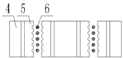
Fig. 2 is a schematic top view of the novel self-tightening brake according to the present invention.
Fig. 3 is a schematic view of a clamping structure of the self-tightening brake of the present invention.
Fig. 4 is a schematic view of the clamping overlooking structure of the self-tightening brake of the present invention.
In the figure: to the pouring weight 1; a wire rope 2; a car 3; a self-tightening device 4; a fixed wedge 5; a movable wedge 6; a fixed seat 7; a traction sheave 8.
Detailed Description
The specific implementation mode is as follows:
the present embodiment will be described with reference to fig. 1 to 4, and the present invention relates to elevator safety protection technology, and more specifically to a novel self-tightening brake, which includes a counterweight 1, a steel wire rope 2, a car 3, a self-tightening device 4, a fixed wedge 5, a movable wedge 6, a fixed seat 7 and a traction sheave 8, and can provide a dual safety brake for an elevator.
The counterweight block 1 and the cage 3 are distributed at two ends of a traction sheave 8, and the peripheries of the steel wire ropes at the counterweight block 1 side and the cage 3 side are respectively provided with a fixed wedge block 5 and a movable wedge block 6. Two movable wedge blocks 6 are arranged on the periphery of the steel wire rope 2, and the two movable wedge blocks 6 are positioned in conical grooves on the fixed wedge blocks 5.
The original brake of the elevator is unchanged, and refer to fig. 1-4.
A self-tightening type band-type brake device is formed by combining a fixed wedge block and a movable wedge block, an electric trigger device is arranged on the movable wedge block, and the trigger device is in an elevator mainboard active trigger control mode. The action mode is as follows: when the main board detects that the speed needs emergency braking or the lift car moves accidentally, a mechanism arranged on the wedge blocks is triggered to act, the two pairs of movable wedge blocks generate downward force according to a mechanical structure, and the inclined surfaces of the wedge blocks respectively clamp steel wire ropes on two sides of a steel wire rope on the traction machine, so that the upper and lower rows of the steel wire ropes can be effectively braked, and the steel wire ropes are more and more tightened to realize the emergency braking effect of the lift car. When the elevator fault is relieved. Must be manually recovered by service personnel.
One movable wedge block is provided with rope grooves corresponding to the diameters and the number of the steel wire ropes.
Of course, the above description is not intended to limit the present invention, and the present invention is not limited to the above examples, and the changes, modifications, additions or replacements made by those skilled in the art within the scope of the present invention also belong to the protection scope of the present invention.
Claims (1)
1. The utility model provides a novel self-tightening formula stopper, includes counterweight block (1), wire rope (2), car (3), self-tightening device (4), fixed voussoir (5), activity voussoir (6), fixing base (7) and driving sheave (8), its characterized in that: counterweight block (1) and car (3) distribute at the both ends of driving sheave (8), be equipped with fixed voussoir (5) and activity voussoir (6) respectively at the wire rope periphery of counterweight block (1) side and car (3) side, wire rope (2) periphery be equipped with two activity voussoir (6), two activity voussoir (6) are located the toper slotted hole on fixed voussoir (5).
Priority Applications (1)
| Application Number | Priority Date | Filing Date | Title |
|---|---|---|---|
| CN201922019229.0U CN211393451U (en) | 2019-11-21 | 2019-11-21 | Novel self-tightening brake |
Applications Claiming Priority (1)
| Application Number | Priority Date | Filing Date | Title |
|---|---|---|---|
| CN201922019229.0U CN211393451U (en) | 2019-11-21 | 2019-11-21 | Novel self-tightening brake |
Publications (1)
| Publication Number | Publication Date |
|---|---|
| CN211393451U true CN211393451U (en) | 2020-09-01 |
Family
ID=72228942
Family Applications (1)
| Application Number | Title | Priority Date | Filing Date |
|---|---|---|---|
| CN201922019229.0U Expired - Fee Related CN211393451U (en) | 2019-11-21 | 2019-11-21 | Novel self-tightening brake |
Country Status (1)
| Country | Link |
|---|---|
| CN (1) | CN211393451U (en) |
Cited By (1)
| Publication number | Priority date | Publication date | Assignee | Title |
|---|---|---|---|---|
| CN115783937A (en) * | 2022-11-09 | 2023-03-14 | 江苏通用电梯有限公司 | Device for preventing elevator car from accidentally moving |
-
2019
- 2019-11-21 CN CN201922019229.0U patent/CN211393451U/en not_active Expired - Fee Related
Cited By (1)
| Publication number | Priority date | Publication date | Assignee | Title |
|---|---|---|---|---|
| CN115783937A (en) * | 2022-11-09 | 2023-03-14 | 江苏通用电梯有限公司 | Device for preventing elevator car from accidentally moving |
Similar Documents
| Publication | Publication Date | Title |
|---|---|---|
| CN103459289B (en) | Lift appliance | |
| CA2082773C (en) | Double-sided wedge brake system for an elevator | |
| EP2112116A1 (en) | Safety device for elevator | |
| JPWO2013157069A1 (en) | Elevator equipment | |
| HK1047078A1 (en) | Method for braking a traction sheave elevator | |
| JP5501995B2 (en) | Elevator equipment | |
| CN104724565A (en) | Elevator brake device with trigger mechanism | |
| CN101622185A (en) | Elevator car and method for holding and braking an elevator car | |
| CN1789102B (en) | Elevator overspeed protecting device | |
| JP5603755B2 (en) | Elevator equipment | |
| KR100889280B1 (en) | Rope Braking System of Elevator | |
| CN206126538U (en) | Building construction elevator promptly prevents weighing down safety device | |
| JP2014114130A (en) | Elevator | |
| CN112456269B (en) | Intelligent braking system | |
| CN105173963A (en) | Elevator car accidental movement control device | |
| CN109019241B (en) | Elevator device and triggering method for elevator protection | |
| CN115072519A (en) | Elevator with prevent weighing down scour protection top safety alarm aggregate unit | |
| CN114772410B (en) | Elevator car deceleration-stopping intelligent system | |
| CN204873336U (en) | Unexpected amount of movement controlling means of elevator car | |
| CN204938624U (en) | Used during elevator falling brake equipment | |
| CN219708981U (en) | Elevator traction rope clamping device | |
| CN222809073U (en) | Elevator braking device | |
| CN107673154B (en) | Elevator power failure safety protection device | |
| CN117446618A (en) | A kind of anti-fall lifting equipment | |
| CN223752186U (en) | Elevator car fall protection device |
Legal Events
| Date | Code | Title | Description |
|---|---|---|---|
| GR01 | Patent grant | ||
| GR01 | Patent grant | ||
| CF01 | Termination of patent right due to non-payment of annual fee |
Granted publication date: 20200901 |
|
| CF01 | Termination of patent right due to non-payment of annual fee |