CN211393196U - Coiling mechanism for fabrics - Google Patents
Coiling mechanism for fabrics Download PDFInfo
- Publication number
- CN211393196U CN211393196U CN201922487376.0U CN201922487376U CN211393196U CN 211393196 U CN211393196 U CN 211393196U CN 201922487376 U CN201922487376 U CN 201922487376U CN 211393196 U CN211393196 U CN 211393196U
- Authority
- CN
- China
- Prior art keywords
- fixedly connected
- rectangular connecting
- winding
- baffle
- rectangular
- Prior art date
- Legal status (The legal status is an assumption and is not a legal conclusion. Google has not performed a legal analysis and makes no representation as to the accuracy of the status listed.)
- Expired - Fee Related
Links
- 239000004744 fabric Substances 0.000 title claims abstract description 16
- 230000007246 mechanism Effects 0.000 title claims abstract description 9
- 238000004804 winding Methods 0.000 claims abstract description 45
- 238000005096 rolling process Methods 0.000 claims abstract description 19
- 239000004753 textile Substances 0.000 claims description 27
- 238000003825 pressing Methods 0.000 claims description 12
- 230000008859 change Effects 0.000 abstract description 2
- 238000004519 manufacturing process Methods 0.000 description 3
- 238000009941 weaving Methods 0.000 description 2
- 230000002860 competitive effect Effects 0.000 description 1
- 239000000835 fiber Substances 0.000 description 1
- 238000012986 modification Methods 0.000 description 1
- 230000004048 modification Effects 0.000 description 1
- 239000007787 solid Substances 0.000 description 1
- 238000006467 substitution reaction Methods 0.000 description 1
- 239000002759 woven fabric Substances 0.000 description 1
Images


Landscapes
- Treatment Of Fiber Materials (AREA)
Abstract
The utility model discloses a coiling mechanism for fabrics, including PMKD, cylinder backup pad, axis of rotation, first rectangle connecting rod, rectangle loop bar, second rectangle connecting rod, decide baffle, threaded rod knob, threaded rod, move baffle, magnet piece, briquetting, decide splint, spring, backup pad, L shape slider, move splint, driving motor, first dwang, belt, second dwang, brush and take-up reel. The utility model has the advantages that: this device is rational in infrastructure, can carry out spacing rolling to the fabrics of different width through adjusting the distance between setting the baffle and moving the baffle, fabrics skew in the time of can effectually preventing the rolling, and this device can convenient and fast install the dismantlement with the winding drum through cup jointing between rectangle loop bar and the second rectangle connecting rod, is convenient for to the change work of winding drum, has improved work efficiency.
Description
Technical Field
The utility model relates to a coiling mechanism specifically is a coiling mechanism for fabrics belongs to weaving coiling mechanism application technical field.
Background
The textile is a product formed by processing and weaving textile fibers, and is divided into woven fabric and knitted fabric, China is one of the earliest countries producing textiles in the world, the main production places are Zhejiang Pu house, Hebei Qinghe and the like, China is a large country for textile production and export, and the Chinese textile industry develops for many years, has very obvious competitive advantages, has the most complete industrial chain in the world, has the highest processing matching level, continuously enhances the self-regulation capacity of a plurality of industrial clusters for the market risk, and provides a solid guarantee for the industry to keep the developed development pace.
The fabrics need carry out the rolling with it in manufacturing process, and traditional winding drum can only carry out the rolling to the fabrics of size singleness, and the fabrics of different width need different receipts spool piece to carry out the rolling, and the receipts spool piece that the winding drum rolling finishes the back needs to be renewed, and it is comparatively time-consuming when changing. Therefore, a coiling mechanism for fabrics is proposed to above-mentioned problem.
SUMMERY OF THE UTILITY MODEL
An object of the utility model is to provide a coiling mechanism for fabrics just in order to solve above-mentioned problem.
The utility model realizes the purpose through the following technical proposal, a rolling device for textiles comprises a fixed bottom plate, a roller supporting plate, a rolling structure and a leveling structure;
two sides of the upper surface of the fixed bottom plate are fixedly connected with one end of a roller supporting plate, a winding structure is fixedly arranged between the other ends of the two roller supporting plates, one end of the upper surface of the fixed bottom plate is fixedly provided with a leveling structure, and the other end of the upper surface of the fixed bottom plate is fixedly provided with a driving motor;
the winding structure comprises a rotating shaft, first rectangular connecting rods, rectangular sleeve rods, second rectangular connecting rods, a fixed baffle, a movable baffle, a magnet block and winding drums, the rotating shaft is rotatably connected to the two drum supporting plates, one end of each of the two rotating shafts is fixedly connected with one end of each of the first rectangular connecting rods, the rectangular sleeve rods are slidably sleeved on the two first rectangular connecting rods, the second rectangular connecting rods are slidably sleeved in inner cavities of the two rectangular sleeve rods, a winding drum is fixedly connected between one ends of the two second rectangular connecting rods, the magnet block is fixedly connected to the connection position of the winding drum and the second rectangular connecting rods, the fixed baffle is fixedly connected to one end of the arc-shaped surface of the winding drum, and the movable baffle is slidably sleeved at the other end of the arc-shaped surface of the winding drum;
level and smooth structure includes briquetting, decide splint, spring, backup pad, L shape slider, moves splint and brush, the one end of the equal fixedly connected with backup pad in PMKD's the upper surface both sides, two splint are decided to fixedly connected with between the other end of backup pad, two the spout cavity has all been seted up, two in the spout cavity equal sliding connection has L shape slider, two the one end of the equal fixedly connected with spring of one end of L shape slider, two on the equal fixedly connected with spout cavity lateral wall of backup pad of the other end of spring, two the spout cavity lateral wall that the backup pad was all run through to the other end of L shape slider just extends to outside the wall, two fixedly connected with moves splint between the L shape slider, decide splint and move the equal fixedly connected with briquetting and brush on the surface of splint.
Preferably, the inside of moving the baffle is seted up threaded hole, threaded hole female connection has the threaded rod, the one end fixedly connected with threaded rod knob of threaded rod.
Preferably, one of them fixedly connected with second dwang on the lateral wall of axis of rotation, the first dwang of driving motor's the terminal fixedly connected with of output shaft, cup joint through the belt between second dwang and the first dwang.
Preferably, the section of each of the two pressing blocks is circular arc.
Preferably, the section of the first rectangular connecting rod is the same as the section of the inner cavity of the rectangular sleeve rod, and the section of the first rectangular connecting rod is the same as the section of the second rectangular connecting rod.
Preferably, the length of the pressing block and the length of the brush are both greater than that of the winding drum.
The utility model has the advantages that:
1. this device is rational in infrastructure, can carry out spacing rolling to the fabrics of different width through adjusting the distance between setting the baffle and moving the baffle, fabrics skew in the time of can effectually preventing the rolling, and this device can convenient and fast install the dismantlement with the winding drum through cup jointing between rectangle loop bar and the second rectangle connecting rod, is convenient for to the change work of winding drum, has improved work efficiency.
2. This device has level and smooth structure, can carry out the tensioning through leveling the structure with the textile fabric before the rolling and flatten, can effectually prevent that the fold from appearing in the textile when the rolling, cleans the upper and lower two sides of textile through the brush simultaneously for when avoiding the rolling with the foreign matter on the textile rolling simultaneously, be fit for using widely.
Drawings
In order to more clearly illustrate the embodiments of the present invention or the technical solutions in the prior art, the drawings needed to be used in the description of the embodiments or the prior art will be briefly described below, it is obvious that the drawings in the following description are only some embodiments of the present invention, and for those skilled in the art, other drawings can be obtained according to the drawings without inventive exercise.
FIG. 1 is a schematic perspective view of the present invention;
FIG. 2 is a schematic side view of the present invention;
fig. 3 is a schematic view of the internal structure of the rolling structure of the present invention;
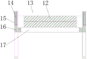
fig. 4 is a schematic view of the internal structure of the leveling structure of the present invention.
In the figure: 1. the fixed baseplate, 2, a roller supporting plate, 3, a rotating shaft, 4, a first rectangular connecting rod, 5, a rectangular sleeve rod, 6, a second rectangular connecting rod, 7, a fixed baffle, 8, a threaded rod knob, 9, a threaded rod, 10, a movable baffle, 11, a magnet block, 12, a pressing block, 13, a fixed clamping plate, 14, a spring, 15, a supporting plate, 16, an L-shaped sliding block, 17, a movable clamping plate, 18, a driving motor, 19, a first rotating rod, 20, a belt, 21, a second rotating rod, 22, a brush, 23 and a winding drum.
Detailed Description
In order to make the objects, features and advantages of the present invention more obvious and understandable, the drawings in the embodiments of the present invention are combined below to clearly and completely describe the technical solutions in the embodiments of the present invention, and obviously, the embodiments described below are only some embodiments of the present invention, but not all embodiments. Based on the embodiments in the present invention, all other embodiments obtained by a person skilled in the art without creative efforts belong to the protection scope of the present invention.
The technical solution of the present invention is further explained by the following embodiments with reference to the accompanying drawings.
In the description of the present invention, it is to be understood that the terms "upper", "lower", "top", "bottom", "inner", "outer", and the like indicate orientations or positional relationships based on those shown in the drawings, and are only for convenience of description and simplicity of description, and do not indicate or imply that the device or element referred to must have a particular orientation, be constructed and operated in a particular orientation, and therefore should not be construed as limiting the present invention.
Referring to fig. 1-4, a winding device for textiles includes a fixed base plate 1, a roller supporting plate 2, a winding structure and a leveling structure;
both sides of the upper surface of the fixed bottom plate 1 are fixedly connected with one end of a roller supporting plate 2, a winding structure is fixedly arranged between the other ends of the two roller supporting plates 2, one end of the upper surface of the fixed bottom plate 1 is fixedly provided with a flat structure, and the other end of the upper surface of the fixed bottom plate 1 is fixedly provided with a driving motor 18;
the winding structure comprises a rotating shaft 3, first rectangular connecting rods 4, rectangular sleeve rods 5, a second rectangular connecting rod 6, a fixed baffle 7, a movable baffle 10, a magnet block 11 and a winding drum 23, the rotating shaft 3 is rotatably connected on the two roller supporting plates 2, one end of each of the two rotating shafts 3 is fixedly connected with one end of the first rectangular connecting rod 4, the rectangular sleeve rods 5 are sleeved on the two first rectangular connecting rods 4 in a sliding manner, the second rectangular connecting rod 6 is sleeved in the inner cavities of the two rectangular sleeve rods 5 in a sliding manner, the winding drum 23 is fixedly connected between one ends of the two second rectangular connecting rods 6, the joint of the winding drum 23 and the second rectangular connecting rod 6 is fixedly connected with a magnet block 11, one end of the arc-shaped surface of the winding drum 23 is fixedly connected with a fixed baffle 7, and the other end of the arc-shaped surface of the winding drum 23 is sleeved with a movable baffle 10 in a sliding manner;
the flattening structure comprises a pressing block 12, a fixed clamping plate 13, a spring 14, a supporting plate 15, an L-shaped sliding block 16, a movable clamping plate 17 and a brush 22, both sides of the upper surface of the fixed bottom plate 1 are fixedly connected with one end of a supporting plate 15, a fixed clamping plate 13 is fixedly connected between the other ends of the two supporting plates 15, chute cavities are formed in the two supporting plates 15, L-shaped sliders 16 are slidably connected in the two chute cavities, one end of each L-shaped slider 16 is fixedly connected with one end of a spring 14, the other ends of the two springs 14 are fixedly connected to the side wall of the chute cavity of the supporting plate 15, the other ends of the two L-shaped sliders 16 penetrate through the side wall of the chute cavity of the supporting plate 15 and extend out of the wall, a movable clamping plate 17 is fixedly connected between the two L-shaped sliders 16, the surfaces of the fixed clamping plate 13 and the movable clamping plate 17 are fixedly connected with a pressing block 12 and a brush 22.
A threaded hole is formed in the movable baffle 10, a threaded rod 9 is connected to the threaded hole in an internal thread mode, and a threaded rod knob 8 is fixedly connected to one end of the threaded rod 9; a second rotating rod 21 is fixedly connected to the side wall of one of the rotating shafts 3, a first rotating rod 19 is fixedly connected to the tail end of an output shaft of the driving motor 18, and the second rotating rod 21 and the first rotating rod 19 are sleeved through a belt 20; the section of each of the two pressing blocks 12 is circular arc; the section of the first rectangular connecting rod 4 is the same as the section of the inner cavity of the rectangular sleeve rod 5, and the section of the first rectangular connecting rod 4 is the same as the section of the second rectangular connecting rod 6; the length of the pressing block 12 and the length of the brush 22 are both larger than that of the winding drum 23.
When the utility model is used, firstly, one end of the textile to be rolled passes between the two brushes 22, then passes between the two pressing blocks 12 again, then the textile is rolled in which the rolling drum 23 is, the distance between the baffle 7 and the movable baffle 10 is adjusted through the width of the textile, the movable baffle 10 is pushed by the staff to move the movable baffle 10 on the rolling drum 23, when the textile is moved to a proper distance, the threaded rod knob 8 is rotated, the threaded rod 9 is driven by the threaded rod knob 8 to rotate in a threaded manner, the threaded rod 9 is pressed against the surface of the rolling drum 23 through the threaded rotation of the threaded rod 9, the movable baffle 10 is fixed, then the driving motor 18 is started, the first rotating rod 19 is driven to rotate through the work of the driving motor 18, the first rotating rod 19 is linked to rotate through the belt 20 and the second rotating rod 21, the rotating shaft 3 is driven to rotate through the second rotating rod 21, the first rectangular connecting rod 4 is driven to rotate by the rotation of the rotating shaft 3, the rectangular loop bar 5 is driven to rotate by the first rectangular connecting rod 4, the second rectangular connecting rod 6 is driven to rotate by the rectangular loop bar 5, the winding drum 23 is driven to rotate by the second rectangular connecting rod 6, the textile is wound by the rotation of the winding drum 23, when the textile is wound and moved, the textile is cleaned by two brushes 22 which are close to the upper surface and the lower surface of the textile, the upper surface and the lower surface of the textile are pressed by two pressing blocks 12, the phenomenon that the textile is folded when being wound is avoided, when the winding drum 23 needs to be replaced after the textile is wound, two rectangular loop bars 5 are moved by a worker, the two rectangular loop bars 5 are separated from the second rectangular connecting rod 6, the winding drum 23 can be taken down, and then a new winding drum 23 is placed between the two rectangular loop bars 5, the two rectangular loop bars 5 are sleeved on the two second rectangular connecting rods 6 again, and the rectangular loop bars 5 are fixedly adsorbed by the two magnet blocks 11, so that the winding drum 23 can be prevented from falling off due to the fact that the rectangular loop bars 5 deviate when the winding drum 23 rotates.
The driving motor 18 adopts a motor of TC7116 model produced by Shenzhen Xintai motor Limited and related matched power supply and circuit thereof.
It is obvious to a person skilled in the art that the invention is not restricted to details of the above-described exemplary embodiments, but that it can be implemented in other specific forms without departing from the spirit or essential characteristics of the invention. The present embodiments are therefore to be considered in all respects as illustrative and not restrictive, the scope of the invention being indicated by the appended claims rather than by the foregoing description, and all changes which come within the meaning and range of equivalency of the claims are therefore intended to be embraced therein. Any reference sign in a claim should not be construed as limiting the claim concerned.
The above embodiments are only used to illustrate the technical solution of the present invention, and not to limit the same; although the present invention has been described in detail with reference to the foregoing embodiments, it should be understood by those skilled in the art that: the technical solutions described in the foregoing embodiments may still be modified, or some technical features may be equivalently replaced; such modifications and substitutions do not depart from the spirit and scope of the present invention in its corresponding aspects.
Claims (6)
1. The utility model provides a coiling mechanism for fabrics which characterized in that: comprises a fixed bottom plate (1), a roller supporting plate (2), a rolling structure and a leveling structure;
both sides of the upper surface of the fixed bottom plate (1) are fixedly connected with one end of a roller supporting plate (2), a winding structure is fixedly arranged between the other ends of the two roller supporting plates (2), one end of the upper surface of the fixed bottom plate (1) is fixedly provided with a flat structure, and the other end of the upper surface of the fixed bottom plate (1) is fixedly provided with a driving motor (18);
the winding structure comprises a rotating shaft (3), first rectangular connecting rods (4), rectangular sleeve rods (5), second rectangular connecting rods (6), a fixed baffle (7), a movable baffle (10), magnet blocks (11) and winding drums (23), the two drum supporting plates (2) are respectively and rotatably connected with the rotating shaft (3), one end of each of the two rotating shafts (3) is respectively and fixedly connected with one end of the first rectangular connecting rod (4), the two first rectangular connecting rods (4) are respectively and slidably sleeved with the rectangular sleeve rods (5), the inner cavities of the two rectangular sleeve rods (5) are respectively and slidably sleeved with the second rectangular connecting rods (6), a winding drum (23) is fixedly connected between one ends of the two second rectangular connecting rods (6), and the magnet blocks (11) are fixedly connected at the connection positions of the winding drums (23) and the second rectangular connecting rods (6), one end of the arc-shaped surface of the winding drum (23) is fixedly connected with a fixed baffle (7), and the other end of the arc-shaped surface of the winding drum (23) is sleeved with a movable baffle (10) in a sliding manner;
the leveling structure comprises a pressing block (12), a fixed clamping plate (13), springs (14), supporting plates (15), L-shaped sliding blocks (16), a movable clamping plate (17) and a brush (22), wherein both sides of the upper surface of the fixed bottom plate (1) are fixedly connected with one end of the supporting plate (15), the fixed clamping plate (13) is fixedly connected between the other ends of the two supporting plates (15), sliding groove cavities are formed in the two supporting plates (15), the L-shaped sliding blocks (16) are slidably connected in the two sliding groove cavities, one end of each L-shaped sliding block (16) is fixedly connected with one end of each spring (14), the other ends of the two springs (14) are fixedly connected to the side wall of each sliding groove cavity of the supporting plate (15), and the other ends of the two L-shaped sliding blocks (16) penetrate through the side wall of each sliding groove cavity of the supporting plate (15) and extend out of, two fixedly connected with moves splint (17) between L shape slider (16), decide splint (13) and move splint (17) on the surface equal fixedly connected with briquetting (12) and brush (22).
2. The winding device for the textile according to claim 1, wherein: the novel adjustable screw driver is characterized in that a threaded hole is formed in the movable baffle (10), a threaded rod (9) is connected to the inner thread of the threaded hole, and a threaded rod knob (8) is fixedly connected to one end of the threaded rod (9).
3. The winding device for the textile according to claim 1, wherein: one of them fixedly connected with second dwang (21) on the lateral wall of axis of rotation (3), the first dwang (19) of the terminal fixedly connected with of output shaft of driving motor (18), cup joint through belt (20) between second dwang (21) and first dwang (19).
4. The winding device for the textile according to claim 1, wherein: the section of each of the two pressing blocks (12) is arc-shaped.
5. The winding device for the textile according to claim 1, wherein: the section of the first rectangular connecting rod (4) is the same as the section of the inner cavity of the rectangular sleeve rod (5), and the section of the first rectangular connecting rod (4) is the same as the section of the second rectangular connecting rod (6).
6. The winding device for the textile according to claim 1, wherein: the length of the pressing block (12) and the length of the brush (22) are both larger than that of the winding drum (23).
Priority Applications (1)
| Application Number | Priority Date | Filing Date | Title |
|---|---|---|---|
| CN201922487376.0U CN211393196U (en) | 2019-12-31 | 2019-12-31 | Coiling mechanism for fabrics |
Applications Claiming Priority (1)
| Application Number | Priority Date | Filing Date | Title |
|---|---|---|---|
| CN201922487376.0U CN211393196U (en) | 2019-12-31 | 2019-12-31 | Coiling mechanism for fabrics |
Publications (1)
| Publication Number | Publication Date |
|---|---|
| CN211393196U true CN211393196U (en) | 2020-09-01 |
Family
ID=72212962
Family Applications (1)
| Application Number | Title | Priority Date | Filing Date |
|---|---|---|---|
| CN201922487376.0U Expired - Fee Related CN211393196U (en) | 2019-12-31 | 2019-12-31 | Coiling mechanism for fabrics |
Country Status (1)
| Country | Link |
|---|---|
| CN (1) | CN211393196U (en) |
Cited By (1)
| Publication number | Priority date | Publication date | Assignee | Title |
|---|---|---|---|---|
| CN112390043A (en) * | 2020-10-12 | 2021-02-23 | 如皋市坝新肠衣有限公司 | Casing winding device |
-
2019
- 2019-12-31 CN CN201922487376.0U patent/CN211393196U/en not_active Expired - Fee Related
Cited By (1)
| Publication number | Priority date | Publication date | Assignee | Title |
|---|---|---|---|---|
| CN112390043A (en) * | 2020-10-12 | 2021-02-23 | 如皋市坝新肠衣有限公司 | Casing winding device |
Similar Documents
| Publication | Publication Date | Title |
|---|---|---|
| CN210619741U (en) | Tensioning mechanism of winding device for spinning | |
| CN212503091U (en) | Fabric winding device for textile processing | |
| CN110884956B (en) | Winding drum convenient for fixing spinning cloth and adjustable in diameter for textile machinery | |
| CN108529323A (en) | A kind of adaptable textile winding device | |
| CN111501321A (en) | Automatic cutting device for textiles | |
| CN210884667U (en) | Weaving workshop is with orderly coiling mechanism of weaving rope | |
| CN209721131U (en) | A kind of anti-offset textile cloth wrap-up | |
| CN214692479U (en) | Surface fabric coiling mechanism convenient to adjust rate of tension | |
| CN213536692U (en) | Cloth coiling mechanism for textile production | |
| CN210366133U (en) | Adjustable spinning winding device | |
| CN210914614U (en) | Textile fabric processing and conveying device | |
| CN211338275U (en) | Coiling machine of wind-up roll is conveniently changed | |
| CN217417651U (en) | Coiling mechanism for film processing | |
| CN218261254U (en) | A textile thread winding device with uniform thread winding function | |
| CN218201245U (en) | Tail cloth collecting device of setting machine for knitted fabric production | |
| CN212892989U (en) | Transmission adjusting device for beating roll, transferring and feeding cotton | |
| CN210133777U (en) | Winding drum for textile machinery | |
| CN213364613U (en) | A textile quality inspection robot | |
| CN110757970A (en) | An integrated production equipment for textile and non-woven fabrics | |
| CN214191833U (en) | Cloth winding device is used in production of high-elastic spring inferior spinning cloth | |
| CN211107522U (en) | Weaving feedway convenient to adjust | |
| CN214726448U (en) | Novel braided bag wire drawing machine's winding displacement equipment | |
| CN214736506U (en) | Stable winding mechanism of rope belt knitting machine | |
| CN209306639U (en) | A printing and dyeing textile winding device | |
| CN210117061U (en) | Polyester fabric winding device for textile machinery |
Legal Events
| Date | Code | Title | Description |
|---|---|---|---|
| GR01 | Patent grant | ||
| GR01 | Patent grant | ||
| CF01 | Termination of patent right due to non-payment of annual fee |
Granted publication date: 20200901 Termination date: 20201231 |
|
| CF01 | Termination of patent right due to non-payment of annual fee |