CN211392738U - Noise elimination cooling conveyer - Google Patents
Noise elimination cooling conveyer Download PDFInfo
- Publication number
- CN211392738U CN211392738U CN201922004724.4U CN201922004724U CN211392738U CN 211392738 U CN211392738 U CN 211392738U CN 201922004724 U CN201922004724 U CN 201922004724U CN 211392738 U CN211392738 U CN 211392738U
- Authority
- CN
- China
- Prior art keywords
- round
- steel
- muffling
- adjacent
- parallel
- Prior art date
- Legal status (The legal status is an assumption and is not a legal conclusion. Google has not performed a legal analysis and makes no representation as to the accuracy of the status listed.)
- Active
Links
- 238000001816 cooling Methods 0.000 title claims abstract description 23
- 230000008030 elimination Effects 0.000 title claims abstract description 10
- 238000003379 elimination reaction Methods 0.000 title claims abstract description 10
- 229910000831 Steel Inorganic materials 0.000 claims abstract description 85
- 239000010959 steel Substances 0.000 claims abstract description 85
- 230000005540 biological transmission Effects 0.000 claims description 11
- 230000007246 mechanism Effects 0.000 claims description 11
- 230000000694 effects Effects 0.000 abstract description 3
- 238000000034 method Methods 0.000 description 4
- 230000008569 process Effects 0.000 description 4
- 230000009471 action Effects 0.000 description 2
- 238000004519 manufacturing process Methods 0.000 description 2
- 238000005096 rolling process Methods 0.000 description 2
- 241001397809 Hakea leucoptera Species 0.000 description 1
- 238000010276 construction Methods 0.000 description 1
- 238000010586 diagram Methods 0.000 description 1
- 230000017525 heat dissipation Effects 0.000 description 1
- 230000009467 reduction Effects 0.000 description 1
- 238000006748 scratching Methods 0.000 description 1
- 230000002393 scratching effect Effects 0.000 description 1
- 230000009466 transformation Effects 0.000 description 1
Images


Landscapes
- Rollers For Roller Conveyors For Transfer (AREA)
Abstract
The utility model relates to a noise elimination cooling conveyer, which comprises a frame, the top surface of frame is provided with the transport face, the anterior segment of transport face includes the backing plate, parallel arrangement's the first round steel about a plurality of are laid to the interval on the backing plate, first round steel is parallel with the direction of delivery of steel ball, the back end of transport face includes a plurality of from preceding to back interval arrangement's gusset, and a plurality of gussets upper berths are equipped with parallel arrangement's the second round steel about a plurality of, the second round steel is parallel with the direction of delivery of steel ball. The utility model relates to a noise elimination cooling conveyer has the advantage that improves the cooling effect, reduces noise pollution, improves workshop environment.
Description
Technical Field
The utility model relates to a noise elimination cooling conveyer belongs to steel ball production facility technical field.
Background
The existing translation type conveyor generally adopts a structure that a motor drives a driving wheel and the driving wheel drives a driven wheel, but the structure can only be used for conveying products with planes generally and can not convey steel ball products due to the shape; some containers or boxes using frames are placed on the conveying belt, the steel balls are placed in the containers or boxes to be conveyed, at the moment, more workers need to be equipped to perform the next operation, the operation is inconvenient, the working efficiency is not high enough, manpower is not saved, the existing equipment can only convey the steel balls on the top surface of the conveying belt, and the up-and-down conveying of the same conveying equipment cannot be realized. In general, in the prior art, a special conveying mechanism for conveying steel balls is not provided.
The patent number is 201510436720.7's utility model discloses a translation formula conveyer, which comprises a motor, the driving shaft, the driven shaft, the driving chain, the action wheel, the follower, a machine support, the motor drives the driving shaft and rotates, the action wheel is connected the driving chain and is moved the follower and rotate, the steel ball carriage is connected to two the inner of driving chain, the below of steel ball carriage is equipped with the backing plate that is used for supporting the steel ball, the backing plate is fixed in the frame, the steel ball is restricted in the clearance between two adjacent round pin axles of steel ball carriage, the steel ball can freely roll between two adjacent round pin axles in transportation process, thereby prevent that certain point of steel ball from always motionless with the backing plate contact, thereby form the flaw on the steel ball surface, effectively guarantee the surface quality. But this translation conveyer sets up in sieve ball mechanism rear usually, and the steel ball that comes out from sieve ball mechanism directly smashes to fall to this translation conveyer's backing plate on, can produce very big noise when the steel ball smashes to fall to the backing plate surface, produces noise pollution to workshop environment, influences that staff's is healthy. In addition, the whole base plate is of a closed structure, and no heat dissipation holes are formed in the surface of the base plate, so that the cooling effect in the steel ball conveying process is greatly influenced.
SUMMERY OF THE UTILITY MODEL
The utility model aims to solve the technical problem that the utility model provides a noise elimination cooling conveyer that improves cooling efficiency, noise pollution reduction, improve workshop environment to above-mentioned prior art.
The utility model provides a technical scheme that above-mentioned problem adopted does: the utility model provides a noise elimination cooling conveyer, includes the frame, the frame top is provided with the transport face, the anterior segment of transport face includes the backing plate, parallel arrangement has a plurality of first round steel about on the backing plate.
Preferably, the first round steel is parallel to the conveying direction of the steel balls.
Preferably, the axial center distance between two adjacent first round steel Wherein: r is the radius of the steel ball, and R is the radius of the first round steel.
Preferably, the first round steel is replaced by a first flat key.
Preferably, the distance between two adjacent first flat keys Wherein: r is the radius of the steel ball, and h is the height of the first flat bond.
Preferably, the rear section of the conveying surface comprises a plurality of rib plates which are arranged from front to back at intervals, a plurality of second round steels are arranged on the front rib plate and the rear rib plate in parallel from left to right, and the second round steels are parallel to the conveying direction of the steel balls.
Preferably, the axial center distance between two adjacent second round bars is smaller than the axial center distance between two adjacent first round bars.
Preferably, the axial center distance between two adjacent second round bars is 1/3 of the axial center distance between two adjacent first round bars.
Preferably, be provided with conveying mechanism in the frame, conveying mechanism includes parallel arrangement's driven shaft and driving shaft from beginning to end, two driving sprocket about being provided with on the driving shaft, two driven sprocket about being provided with on the driven shaft, the driving chain has been around having placed between driving sprocket and the driven sprocket, and the parallel arrangement has a plurality of round pins around controlling between two driving chains.
Compared with the prior art, the utility model has the advantages of:
1. the utility model discloses laid round steel or flat key along the steel ball direction of delivery interval on the anterior segment backing plate that is close to sieve ball mechanism, the steel ball that comes out from sieve ball mechanism from the steel ball can not directly pound and fall on the backing plate, but contacts with round steel or flat key that interval laid on the backing plate, can greatly reduce the steel ball and drop the noise that produces on the conveyer, greatly reduced the noise pollution in workshop, improved workshop production environment;
2. the utility model discloses original backing plate has been cancelled to the conveyer rear end, and changes into the round steel or the parallel key of laying along the direction of delivery interval of steel ball, and round steel or parallel key support through the gusset of arranging around, are hollow out construction between two adjacent round steels, and the steel ball supports through round steel or parallel key that the interval was laid, can prevent unordered the rolling of steel ball on the one hand, and on the other hand can effectively improve the cooling effect of steel ball in transportation process.
Drawings
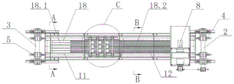
Fig. 1 is a schematic structural view of the noise elimination cooling conveyor of the present invention.
Fig. 2 is a front view of fig. 1.
Fig. 3 is a sectional view taken along line a-a of fig. 1.
Fig. 4 is a sectional view taken along line B-B in fig. 1.
Fig. 5 is a schematic view of the connection between the pin and the driving chain in the section C of fig. 1.
Fig. 6 is a schematic diagram of the limit positions at which the axial center distance between two adjacent first round steels can support the steel balls.
FIG. 7 is a schematic view of the limit position of the axial spacing between two adjacent first flat keys capable of supporting the steel ball.
Wherein:
Drive sprocket 4
Clamp spring 14
Pin bush 16
Guide flat key 17
Conveying surface 18
Front section 18.1
And a rear section 18.2.
Detailed Description
The present invention will be described in further detail with reference to the following embodiments.
Referring to fig. 1 to 7, the utility model relates to a noise elimination cooling conveyor, including frame 1, frame 1 top is provided with conveying surface 18, conveying surface 18 includes anterior segment 18.1 and back end 18.2, anterior segment 18.1 includes backing plate 9, a plurality of first round steel 11 have been arranged in parallel about backing plate 9, first round steel 11 is parallel with the direction of delivery of steel ball;
the length of the front section 18.1 is 150-250 mm;
the axial center distance between two adjacent first round steel 11 Wherein: r is the radius of the steel ball, and R is the radius of the first
round steel 11;
the first round steel 11 can be replaced by a first flat key, and the distance between two adjacent first flat keys
 Wherein: r is the radius of the steel ball, and h is the height of the first flat bond;
the rear section 18.2 comprises a plurality of rib plates 10 which are arranged from front to back at intervals, the rib plates 10 are arranged along the left-right direction, a plurality of second round steel 12 are arranged on the front rib plate 10 and the rear rib plate 10 in parallel left and right, and the second round steel 12 is parallel to the conveying direction of the steel balls;
the axial center distance between two adjacent second round steel 12 is smaller than the axial center distance between two adjacent first round steel 11;
the axial center distance between two adjacent second round steel 12 is 1/3 of the axial center distance between two adjacent first round steel 11;
the conveying mechanism is arranged on the rack 1 and comprises a driven shaft 3 and a driving shaft 2 which are arranged in parallel front and back, a left driving chain wheel 4 and a right driving chain wheel 4 are arranged on the driving shaft 2, a left driven chain wheel 5 and a right driven chain wheel 5 are arranged on the driven shaft 3, a transmission chain 6 is wound between the driving chain wheels 4 and the driven chain wheels 5, and a plurality of pin shafts 7 are arranged between the left transmission chain wheel 6 and the right transmission chain wheel 6 in parallel front and back;
the transmission chain 6 is a chain plate type transmission chain, the transmission chain 6 comprises a plurality of outer chain plates 61 and inner chain plates 62 which are opposite to each other in pairs, shaft holes are formed in two ends of each of the outer chain plates 61 and the inner chain plates 62, rollers 13 are arranged between the shaft holes of two adjacent inner chain plates 62 and the shaft holes of two adjacent outer chain plates 61, the outer ends of the pin shafts 7 sequentially penetrate through the shaft holes of two adjacent inner chain plates 62, the rollers 13 and the shaft holes of two adjacent outer chain plates 61, and clamp springs 14 are arranged at the outer ends of the pin shafts 7;
a gasket 15 is arranged between the clamp spring 14 and the outer side surface of the outer chain plate 61;
a guide flat key 17 is arranged below the roller 13, the width of the guide flat key 17 is matched with the distance between the outer chain plate 61 and the inner chain plate 62, and the guide flat key 17 has the functions of guiding and preventing the chain plates from scratching the rack 1;
a pin shaft sleeve 16 is sleeved on the pin shaft 7, and the pin shaft sleeve 16 can reduce the friction force generated in the rolling process of the steel ball;
the heights of the outer chain plate 61 and the inner chain plate 62 are larger than the radius of the steel ball, so that the steel ball can be prevented from falling;
the chain pitch of the transmission chain 6 is larger than the diameter of the steel ball;
the height of the axial center of the pin shaft 7 is lower than the height of the center of the steel ball, so that the steel ball is prevented from being supported by the pin shaft 7 in the conveying process;
the driving shaft 2 is driven by a motor 8, the motor 8 is installed on the rack 1 through a motor base, and the motor 8 is connected with the driving shaft 2 in a chain transmission mode.
In addition to the above embodiments, the present invention also includes other embodiments, and all technical solutions formed by equivalent transformation or equivalent replacement should fall within the protection scope of the claims of the present invention.
Claims (10)
1. A noise elimination cooling conveyer which characterized in that: including frame (1), frame (1) top is provided with transport face (18), anterior segment (18.1) of transport face (18) include backing plate (9), parallel arrangement has a plurality of first round steel (11) about on backing plate (9).
2. A muffling cooling conveyor according to claim 1, wherein: the first round steel (11) is parallel to the conveying direction of the steel balls.
3. A muffling cooling conveyor according to claim 1, wherein: the axial center distance between two adjacent first round steel (11) Wherein: r is the radius of the steel ball, and R is the radius of the first round steel.
4. A muffling cooling conveyor according to claim 1, wherein: the first round steel (11) is replaced by a first flat key.
5. The muffling cooling conveyor of claim 4, wherein: distance between two adjacent first flat keys Wherein: r is the radius of the steel ball, and h is the height of the first flat bond.
6. A muffling cooling conveyor according to claim 1, wherein: the rear section (18.2) of the conveying surface (18) comprises a plurality of second round steels (12) which are arranged in parallel from left to right, and the second round steels (12) are parallel to the conveying direction of the steel balls.
7. A muffling cooling conveyor according to claim 6, wherein: a plurality of rib plates (10) are arranged in parallel front and back below the second round steels (12), and the second round steels (12) are erected on the rib plates (10).
8. A muffling cooling conveyor according to claim 6, wherein: the axial center distance between two adjacent second round bars (12) is smaller than the axial center distance between two adjacent first round bars (11).
9. A muffling cooling conveyor according to claim 8, wherein: the axial center distance between two adjacent second round bars (12) is 1/3 of the axial center distance between two adjacent first round bars (11).
10. A muffling cooling conveyor according to claim 1, wherein: the automatic conveying mechanism is characterized in that a conveying mechanism is arranged on the rack (1), the conveying mechanism comprises a driven shaft (3) and a driving shaft (2) which are arranged in a front-back parallel mode, a left driving chain wheel and a right driving chain wheel (4) are arranged on the driving shaft (2), a left driven chain wheel and a right driven chain wheel (5) are arranged on the driven shaft (3), a transmission chain (6) is wound between the driving chain wheels (4) and the driven chain wheels (5), and a plurality of pin shafts (7) are arranged between the left transmission chain wheel and the right transmission chain (6) in a front-.
Priority Applications (1)
| Application Number | Priority Date | Filing Date | Title |
|---|---|---|---|
| CN201922004724.4U CN211392738U (en) | 2019-11-19 | 2019-11-19 | Noise elimination cooling conveyer |
Applications Claiming Priority (1)
| Application Number | Priority Date | Filing Date | Title |
|---|---|---|---|
| CN201922004724.4U CN211392738U (en) | 2019-11-19 | 2019-11-19 | Noise elimination cooling conveyer |
Publications (1)
| Publication Number | Publication Date |
|---|---|
| CN211392738U true CN211392738U (en) | 2020-09-01 |
Family
ID=72225404
Family Applications (1)
| Application Number | Title | Priority Date | Filing Date |
|---|---|---|---|
| CN201922004724.4U Active CN211392738U (en) | 2019-11-19 | 2019-11-19 | Noise elimination cooling conveyer |
Country Status (1)
| Country | Link |
|---|---|
| CN (1) | CN211392738U (en) |
Cited By (1)
| Publication number | Priority date | Publication date | Assignee | Title |
|---|---|---|---|---|
| CN110817273A (en) * | 2019-11-19 | 2020-02-21 | 江阴东邦钢球机械有限公司 | Noise elimination cooling conveyer |
-
2019
- 2019-11-19 CN CN201922004724.4U patent/CN211392738U/en active Active
Cited By (2)
| Publication number | Priority date | Publication date | Assignee | Title |
|---|---|---|---|---|
| CN110817273A (en) * | 2019-11-19 | 2020-02-21 | 江阴东邦钢球机械有限公司 | Noise elimination cooling conveyer |
| CN110817273B (en) * | 2019-11-19 | 2024-07-16 | 江阴东邦钢球机械有限公司 | Silencing and cooling conveyor |
Similar Documents
| Publication | Publication Date | Title |
|---|---|---|
| CN110434075B (en) | Multilayer cross belt sorter | |
| CN201458234U (en) | Telescopic belt conveyor | |
| CN212830965U (en) | Intermittent steel mould feeder | |
| CN204638733U (en) | A kind of section steel cooling bed | |
| CN215923442U (en) | Axle conveying line | |
| CN212474888U (en) | Plate arranging device | |
| CN110817273B (en) | Silencing and cooling conveyor | |
| CN107758217B (en) | Circulating vertical conveyor | |
| CN210730194U (en) | Vertical cross-belt sorting machine | |
| CN221875766U (en) | Automatic palletizing device | |
| CN220484391U (en) | Hole ring feeding mechanism | |
| CN217866481U (en) | I-shaped wheel transfer device for steel cord production | |
| CN217650132U (en) | Double-tube conveying device | |
| CN212420164U (en) | Positioning device for reinforcing ribs for elevator door plate assembly | |
| CN214297708U (en) | A skip car for gear heat treatment | |
| CN212502357U (en) | Pipe pile mould conveyor | |
| CN210213681U (en) | Conveying mechanism of container gooseneck tunnel | |
| CN220010988U (en) | Scratch-proof flat steel conveying chain | |
| CN203211881U (en) | Steel ball conveyor | |
| CN210029009U (en) | Linear material warehouse suitable for automatic lamination of transformer cores | |
| CN208948163U (en) | A kind of two chain conveyers | |
| CN215325052U (en) | Raw material adding device for iron and steel smelting | |
| CN224072351U (en) | Discharging mechanism for steel bar surface coating spraying equipment | |
| CN220906412U (en) | Pneumatic side displacement steel device | |
| CN219729442U (en) | Noise reduction device for straight-line crossed belt sorter |
Legal Events
| Date | Code | Title | Description |
|---|---|---|---|
| GR01 | Patent grant | ||
| GR01 | Patent grant |