CN211390856U - A tire dismounting assist device - Google Patents
A tire dismounting assist device Download PDFInfo
- Publication number
- CN211390856U CN211390856U CN201922017149.1U CN201922017149U CN211390856U CN 211390856 U CN211390856 U CN 211390856U CN 201922017149 U CN201922017149 U CN 201922017149U CN 211390856 U CN211390856 U CN 211390856U
- Authority
- CN
- China
- Prior art keywords
- tire
- lower beam
- bracket
- shaped bracket
- adjustable screw
- Prior art date
- Legal status (The legal status is an assumption and is not a legal conclusion. Google has not performed a legal analysis and makes no representation as to the accuracy of the status listed.)
- Expired - Fee Related
Links
Images


Landscapes
- Vehicle Cleaning, Maintenance, Repair, Refitting, And Outriggers (AREA)
Abstract
本实用新型公开了一种轮胎拆装助力装置,该装置包括轮胎支架、液压千斤顶、可调节螺杆、工字型支架、滑道、下梁和导向杆。所述滑道位于框架立柱的内侧,与工字型支架左右两端的滚轮相配合,所述工字型支架通过可调节螺杆和导向杆连接下梁,工字型支架和下梁的两端均安装滚轮,可实现在滑道内上下移动。在所述工字型支架前端固定安装两个轮胎支架,所述轮胎支架包括轴承连接的滚筒和支架轴,可实现轮胎在轮胎支架上旋转。所述液压千斤顶连接下梁和底座,能推拉下梁上下移动。该装置实现了轮胎拆装的定位准确,轮胎拆装方便快捷,效率高。
The utility model discloses a tire disassembly and assembly assist device, which comprises a tire bracket, a hydraulic jack, an adjustable screw rod, an I-shaped bracket, a slideway, a lower beam and a guide rod. The slideway is located on the inner side of the frame column and is matched with the rollers at the left and right ends of the I-shaped bracket. The I-shaped bracket is connected to the lower beam through an adjustable screw rod and a guide rod. Both ends of the I-shaped bracket and the lower beam are Install rollers to move up and down in the slideway. Two tire brackets are fixedly installed at the front end of the I-shaped bracket, and the tire bracket includes a roller connected by a bearing and a bracket shaft, which can realize the rotation of the tire on the tire bracket. The hydraulic jack connects the lower beam and the base, and can push and pull the lower beam to move up and down. The device realizes accurate positioning of tire disassembly and assembly, convenient and quick tire disassembly and assembly, and high efficiency.
Description
技术领域technical field
本实用新型应用于汽车维修领域,具体涉及一种用于轮胎拆装的助力装置。The utility model is applied to the field of automobile maintenance, in particular to a power assist device used for tire disassembly and assembly.
背景技术Background technique
随着我国汽车人均拥有量正在逐年增加,我国已成为世界汽车生产消费大国,汽车销售量也居世界前列。作为易损件和定期更换件的汽车轮胎使用量也在逐年增加。当轮胎达到使用年限或行驶里程后需要更换新轮胎,或当出现扎胎后也需要拆卸轮胎进行维修。轮胎加轮毂一般重量在25—40公斤,若没有专用工具,轮胎的拆装需多人合作,费时费力,劳动效率低。As my country's per capita car ownership is increasing year by year, my country has become the world's largest automobile production and consumption country, and automobile sales are also in the forefront of the world. The use of car tires as wearing parts and regular replacement parts is also increasing year by year. When the tire reaches its useful life or mileage, it needs to be replaced with a new tire, or when a puncture occurs, the tire needs to be removed for maintenance. The weight of tires and hubs is generally 25-40 kg. If there are no special tools, the disassembly and assembly of tires requires the cooperation of many people, which is time-consuming and labor-intensive, and labor efficiency is low.
专利CN105620211B给出了一种轮胎拆卸装置,该装置适用于大型轮胎。轮胎拆卸装置相关专利有很多,缺点有的是结构和操作复杂,有的定位费时费力。Patent CN105620211B presents a tire dismounting device, which is suitable for large tires. There are many patents related to tire removal devices, some of which are complicated in structure and operation, and some are time-consuming and labor-intensive in positioning.
发明内容SUMMARY OF THE INVENTION
本实用新型解决的技术问题是:提供一种轮胎拆装助力装置,可实现快速准确定位,使得轮毂和制动盘上的螺栓孔对齐,提高工作效率。The technical problem solved by the utility model is: to provide a tire disassembly and assembly booster device, which can realize fast and accurate positioning, align the bolt holes on the wheel hub and the brake disc, and improve the work efficiency.
本实用新型所采用的技术方案是:该轮胎拆装助力装置,包括垂直框架、水平底座、万向轮、轮胎支架、液压千斤顶、可调节螺杆、工字型支架、滑道、下梁和导向杆,所述底座与框架焊接固定,万向轮固定在底座下面,用于调整移动方向。所述滑道位于框架立柱的内侧,与工字型支架左右两端的滚轮相配合,所述工字型支架通过可调节螺杆和导向杆连接下梁,所述可调节螺杆能调整工字型支架上下移动;工字型支架和下梁的两端均安装滚轮,可实现在滑道内上下移动。在所述工字型支架前端固定安装两个轮胎支架,所述轮胎支架包括轴承连接的滚筒和支架轴,可实现轮胎在轮胎支架上旋转。所述液压千斤顶连接下梁和底座,能推拉下梁上下移动。所述导向杆固定连接下梁,滑动连接工字型支架,对工字型支架上下移动起到导向作用。The technical scheme adopted by the utility model is: the tire disassembly and assembly assisting device includes a vertical frame, a horizontal base, a universal wheel, a tire bracket, a hydraulic jack, an adjustable screw rod, an I-shaped bracket, a slideway, a lower beam and a guide The base is welded and fixed with the frame, and the universal wheel is fixed under the base to adjust the moving direction. The slideway is located on the inner side of the frame column and is matched with the rollers at the left and right ends of the I-shaped bracket. The I-shaped bracket is connected to the lower beam through an adjustable screw rod and a guide rod, and the adjustable screw rod can adjust the I-shaped bracket. Move up and down; both ends of the I-shaped bracket and the lower beam are equipped with rollers, which can move up and down in the slideway. Two tire brackets are fixedly installed at the front end of the I-shaped bracket, and the tire bracket includes a roller and a bracket shaft connected by a bearing, which can realize the rotation of the tire on the tire bracket. The hydraulic jack connects the lower beam and the base, and can push and pull the lower beam to move up and down. The guide rod is fixedly connected to the lower beam and slidably connected to the I-shaped bracket, and plays a guiding role for the up and down movement of the I-shaped bracket.
本实用新型的有益效果是:实现轮胎拆装的定位准确,轮胎拆装方便快捷,效率高。The beneficial effects of the utility model are: accurate positioning of tire disassembly and assembly, convenient and quick tire disassembly and assembly, and high efficiency.
附图说明Description of drawings
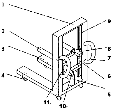
图1为本实用新型立体结构示意图;1 is a schematic diagram of the three-dimensional structure of the present utility model;
图2为工字型支架俯视图;Figure 2 is a top view of an I-shaped bracket;
其中:1-框架、2-轮胎支架、3-底座、4-万向轮、5-液压千斤顶、6-可调节螺杆、7-推手、8-工字型支架、9-滑道、10-下梁、11-导向杆、12-滚轮、13-螺纹孔、14-导向孔。Among them: 1-frame, 2-tire bracket, 3-base, 4-universal wheel, 5-hydraulic jack, 6-adjustable screw, 7-push handle, 8-I-shaped bracket, 9-slide, 10- Lower beam, 11-guide rod, 12-roller, 13-threaded hole, 14-guide hole.
具体实施方式Detailed ways
本实用新型轮胎拆装助力装置的三维视图如附图1所示,包括垂直框架1,轮胎支架2、水平底座3、万向轮4、液压千斤顶5、可调节螺杆6、推手7、工字型支架8、滑道9、下梁10等。以操作的方向为前,所述框架1包括左右两个立柱,两个推手7分部焊接在左右立柱上。在框架立柱的内侧加工有滑道9。水平底座3与框架1焊接固定,万向轮4固定在底座3的下面,用于调整移动方向。在所述滑道9内安装可以滑动的移动支架,该移动支架包括工字型支架8和下梁10,工字型支架8和下梁10通过可调节螺杆6和导向杆11连接,可调节螺杆6和导向杆11固定在下梁10上,可调节螺杆6可旋转。工字型支架8与可调节螺杆6螺纹连接,与导向杆11滑动连接,这样,可调节螺杆6旋转时,可在导向杆11的作用下,可调整工字型支架8上下移动。在工字型支架8的前面安装有两个轮胎支架2,轮胎支架2用于拆装轮胎时放置轮胎。轮胎支架2上的滚筒经过轴承可以绕轮胎支架轴进行转动,便于圆周方向调整轮胎与轮毂的螺栓定位。液压千斤顶5连接下梁10和底座3,可推拉下梁10,使得移动支架在滑道9内快速移动,可快速调整轮胎支架2的高度,从而快速调整轮胎与轮毂的相对位置。当需要微调时,可采用可调节螺杆6。The three-dimensional view of the tire disassembly and assembly assist device of the present utility model is shown in FIG. 1, including a
工字型支架8左右两端的滚轮12套装在滑道9内,与滑道9相配合,见附图2,可实现工字型支架8在滑道9内上下移动,下梁10的两端也安装滚轮12,与工字型支架8一起在滑道9内移动。在工字型支架8上加工有与可调节螺杆6配合的螺纹孔13,以及与导向杆11配合的导向孔14。The
本实用新型通过调整万向轮4、液压千斤顶5和可调节螺杆6来调整轮胎支架的位置,从而实现轮胎的拆装。以安装轮胎为例,推手将轮胎推到机动车制动器的正下方,使用液压千斤顶将轮胎提升到指定高度,通过在轮胎支架上转动轮胎,可调节螺杆6微调轮胎高度,使得轮毂上的螺栓孔和轮胎制动器或制动盘上的螺栓孔对齐,方便轮胎螺栓的安装。The utility model adjusts the position of the tire bracket by adjusting the
本实用新型主要应用于轮胎店、汽车维修店等,实现汽车轮胎的快速拆装,提高工作效率,采用该轮胎拆装助理装置,定位准确,轮胎拆装方便快捷、省时省力。The utility model is mainly used in tire shops, automobile repair shops, etc., to realize quick disassembly and assembly of automobile tires, and improve work efficiency.
Claims (2)
Priority Applications (1)
| Application Number | Priority Date | Filing Date | Title |
|---|---|---|---|
| CN201922017149.1U CN211390856U (en) | 2019-11-21 | 2019-11-21 | A tire dismounting assist device |
Applications Claiming Priority (1)
| Application Number | Priority Date | Filing Date | Title |
|---|---|---|---|
| CN201922017149.1U CN211390856U (en) | 2019-11-21 | 2019-11-21 | A tire dismounting assist device |
Publications (1)
| Publication Number | Publication Date |
|---|---|
| CN211390856U true CN211390856U (en) | 2020-09-01 |
Family
ID=72230885
Family Applications (1)
| Application Number | Title | Priority Date | Filing Date |
|---|---|---|---|
| CN201922017149.1U Expired - Fee Related CN211390856U (en) | 2019-11-21 | 2019-11-21 | A tire dismounting assist device |
Country Status (1)
| Country | Link |
|---|---|
| CN (1) | CN211390856U (en) |
Cited By (2)
| Publication number | Priority date | Publication date | Assignee | Title |
|---|---|---|---|---|
| CN113715556A (en) * | 2021-08-21 | 2021-11-30 | 邱林 | Automobile manufacturing spare part auxiliary assembly equipment |
| CN114043821A (en) * | 2021-09-27 | 2022-02-15 | 中国煤炭科工集团太原研究院有限公司 | Mining explosion-proof rubber tyre dismouting device |
-
2019
- 2019-11-21 CN CN201922017149.1U patent/CN211390856U/en not_active Expired - Fee Related
Cited By (2)
| Publication number | Priority date | Publication date | Assignee | Title |
|---|---|---|---|---|
| CN113715556A (en) * | 2021-08-21 | 2021-11-30 | 邱林 | Automobile manufacturing spare part auxiliary assembly equipment |
| CN114043821A (en) * | 2021-09-27 | 2022-02-15 | 中国煤炭科工集团太原研究院有限公司 | Mining explosion-proof rubber tyre dismouting device |
Similar Documents
| Publication | Publication Date | Title |
|---|---|---|
| CN207548635U (en) | Coupler knuckle for car coupler dismounts tooling | |
| CN213318572U (en) | Frame-shaped component welding side-tipping device | |
| CN104986199A (en) | Device for dismounting and mounting tire | |
| CN108640025B (en) | Dismounting device for unit brake of urban rail vehicle | |
| CN218343196U (en) | Tire replacement auxiliary device for automobile maintenance | |
| CN205043708U (en) | Motor overhauls specialized tool | |
| CN112518660B (en) | Dismounting device for rolling pin of nut pair of subway vehicle door | |
| CN211866775U (en) | Automobile wheel hub cutting device | |
| CN206203790U (en) | A kind of four-wheel aligner lifting machine | |
| CN203711479U (en) | Roller bearing seat assembling and disassembling machine | |
| CN218798183U (en) | Roller dismounting platform | |
| CN116945823A (en) | Swinging type tire removing machine and working method thereof | |
| CN205706024U (en) | A kind of card passenger tyre changer | |
| CN205257901U (en) | A bayonet lock structure for locking holder | |
| CN115446248A (en) | Wheel hub dress trim cover riveting production facility | |
| CN202742983U (en) | Small trolley provided with truck wheels | |
| CN222491739U (en) | A multi-point positioning device for wheel punching | |
| CN221253758U (en) | Tire installation lift | |
| CN207824983U (en) | A kind of reverse osmosis membrane bead cutter | |
| CN207449192U (en) | A kind of movable pressing machine | |
| CN223264852U (en) | A milling machine cutter head disassembly tool | |
| CN220837746U (en) | Ring rolling machine capable of achieving rapid machining | |
| CN213679634U (en) | A portable tire removal device | |
| CN107457552B (en) | Quick disassembly and assembly device of transmission shaft of large-scale railway track maintenance machinery and its working method | |
| CN212532161U (en) | Front and rear motor dismounting platform for electric automobile |
Legal Events
| Date | Code | Title | Description |
|---|---|---|---|
| GR01 | Patent grant | ||
| GR01 | Patent grant | ||
| CF01 | Termination of patent right due to non-payment of annual fee |
Granted publication date: 20200901 |
|
| CF01 | Termination of patent right due to non-payment of annual fee |