CN211386373U - Gas generator J lead wire is put in order to press shape device - Google Patents
Gas generator J lead wire is put in order to press shape device Download PDFInfo
- Publication number
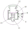
- CN211386373U CN211386373U CN201922236150.3U CN201922236150U CN211386373U CN 211386373 U CN211386373 U CN 211386373U CN 201922236150 U CN201922236150 U CN 201922236150U CN 211386373 U CN211386373 U CN 211386373U
- Authority
- CN
- China
- Prior art keywords
- fixedly connected
- plate
- backup pad
- frame
- supporting plate
- Prior art date
- Legal status (The legal status is an assumption and is not a legal conclusion. Google has not performed a legal analysis and makes no representation as to the accuracy of the status listed.)
- Expired - Fee Related
Links
- WABPQHHGFIMREM-UHFFFAOYSA-N lead(0) Chemical compound [Pb] WABPQHHGFIMREM-UHFFFAOYSA-N 0.000 title claims abstract description 15
- 230000006978 adaptation Effects 0.000 claims abstract description 5
- 238000007493 shaping process Methods 0.000 claims description 14
- 238000004513 sizing Methods 0.000 claims 5
- 230000008859 change Effects 0.000 abstract description 2
- 239000007789 gas Substances 0.000 description 11
- 238000000034 method Methods 0.000 description 5
- 238000003825 pressing Methods 0.000 description 4
- 230000009471 action Effects 0.000 description 3
- 238000004519 manufacturing process Methods 0.000 description 2
- VNWKTOKETHGBQD-UHFFFAOYSA-N methane Chemical compound C VNWKTOKETHGBQD-UHFFFAOYSA-N 0.000 description 2
- 230000008569 process Effects 0.000 description 2
- 241000282836 Camelus dromedarius Species 0.000 description 1
- 230000004075 alteration Effects 0.000 description 1
- 230000009286 beneficial effect Effects 0.000 description 1
- 238000002485 combustion reaction Methods 0.000 description 1
- 239000002283 diesel fuel Substances 0.000 description 1
- 230000000694 effects Effects 0.000 description 1
- 230000007613 environmental effect Effects 0.000 description 1
- 238000012423 maintenance Methods 0.000 description 1
- 238000012986 modification Methods 0.000 description 1
- 230000004048 modification Effects 0.000 description 1
- 239000003345 natural gas Substances 0.000 description 1
- 238000010248 power generation Methods 0.000 description 1
- 230000036632 reaction speed Effects 0.000 description 1
- 238000006467 substitution reaction Methods 0.000 description 1
- 239000000758 substrate Substances 0.000 description 1
Images



Landscapes
- Gripping Jigs, Holding Jigs, And Positioning Jigs (AREA)
Abstract
The utility model discloses a gas generator J lead wire integer pressure shape device, the concave circular arc template of right side fixedly connected with of second backup pad, the convex circular arc template of the left side fixedly connected with and concave circular arc template looks meshing of third backup pad, the equal sliding connection in both sides at first backup pad top has fixed frame, the utility model relates to a generator rotor rule equipment technical field. This gas generator J lead wire is put and is pressed shape device, fixedly connected with second slide rail between the front and the back through first backup pad top, the bottom fixedly connected with of first screw thread frame and the slider of second slide rail looks adaptation, can make the work piece under the tight condition of clamp, when meetting the work piece by the putting of different models, convenient and fast's change is put and is pressed shape device as required, thereby make the area of device reduce, adjust the tension of work piece according to the needs of self simultaneously, the work piece has been reduced because the damage of tension to self, the practicality of device has been improved.
Description
Technical Field
The utility model relates to a generator rotor rule technical field specifically is a gas generator J lead wire is put and is pressed shape device.
Background
The gas generator is a novel and high-efficiency new energy generator which takes combustible gases such as liquefied gas, natural gas and the like as combustion products to replace gasoline and diesel oil as engine power, has the advantages of wide output power range, reliable and high starting and running, good power generation quality, light weight, small volume, simple maintenance, low frequency noise and the like, because the generator only rotates when working, the electric regulation has fast reaction speed, stable work, high precision of the output voltage and frequency of the generator and small fluctuation, when the load is reduced by 50 percent and 75 percent by sudden air filling, the unit haunch gathering fur camel running is very stable and is superior to the electrical performance index of a diesel generating set, the time from the successful cold start to the full load is only 30 seconds, and the international regulation indicates that the diesel generator carries load 3 minutes after being successfully started, and the gas turbine generator set can ensure the success rate of starting at any environmental temperature and climate.
When the shaping device is used, workpieces which are shaped by shaping and have different models cannot be met, multiple shaping devices are needed, the occupied area of the shaping devices is large, different shaping devices are prepared according to different workpiece models, and the production cost is greatly improved.
SUMMERY OF THE UTILITY MODEL
The utility model provides a not enough to prior art, the utility model provides a gas generator J lead wire integer pressing device has solved the problem that the integer pressing device need prepare different integer pressing devices according to the difference of work piece.
In order to achieve the above purpose, the utility model discloses a following technical scheme realizes: a J lead shaping device of a gas generator comprises a first supporting plate, a second supporting plate and a third supporting plate, wherein the bottoms of the second supporting plate and the third supporting plate are slidably connected with the top of the first supporting plate, the left side of the top of the first supporting plate is fixedly connected with a first hydraulic rod, the right side of the top of the first supporting plate is fixedly connected with a second hydraulic rod, the right side of the second supporting plate is fixedly connected with a concave arc template, the left side of the third supporting plate is fixedly connected with a convex arc template meshed with the concave arc template, both sides of the top of the first supporting plate are slidably connected with a fixed frame, both sides of the inner wall of the fixed frame are fixedly connected with first slide rails, a sliding plate is slidably connected between the two opposite sides of the first slide rails, the back of the sliding plate is fixedly connected with a fixed plate, and the fixed plate penetrates through the fixed frame and extends, the front of the sliding plate is fixedly connected with a spring plate, the front of the spring plate penetrates through the front of the fixing frame and extends to the outside of the fixing frame, and the front of the second supporting plate and the front of the third supporting plate are both provided with clamping holes matched with the fixing plate.
Preferably, a spring is fixedly connected between the front face of the sliding plate and the front face of the inner wall of the fixed frame and positioned on the surface of the spring plate, and a connecting plate is fixedly connected to the back face of the top of the first supporting plate.
Preferably, the front surface of the top of the first supporting plate is fixedly connected with a first threaded frame, and two sides of the first threaded frame are in threaded connection with first threaded rods.
Preferably, the back fixedly connected with second thread frame at first backup pad top, the equal threaded connection in both sides of second thread frame has the second threaded rod.
Preferably, the back surface of the first thread frame is provided with a first through hole matched with the workpiece, and the front surface of the second thread frame is provided with a second through hole matched with the workpiece.
Preferably, the top of the first supporting plate is fixedly connected with a second sliding rail, and the bottom of the first thread frame is fixedly connected with a sliding block matched with the second sliding rail.
Advantageous effects
The utility model provides a gas generator J lead wire is put in order to press shape device. Compared with the prior art, the method has the following beneficial effects:
(1) this gas generator J lead wire integer pressure shape device, the concave circular arc template of right side fixedly connected with through the second backup pad, the convex circular arc template that left side fixedly connected with and concave circular arc template of third backup pad engaged with, the equal sliding connection in both sides at first backup pad top has fixed frame, just be located the fixed surface that the spring board was connected with the spring between the front of sliding plate and the front of fixed frame inner wall, the block hole with fixed plate looks adaptation is all seted up with the front of third backup pad to the second backup pad, can make when meetting the work piece of being integer pressure shape of different models, can be as required convenient and fast's change integer pressure shape device, thereby make the area of device reduce, and the production cost is saved, and the practicality of device is improved.
(2) This gas generator J lead wire is put and is pressed shape device through fixedly connected with second slide rail between the front at first backup pad top and the back, and the bottom fixedly connected with of first screw thread frame and the slider of second slide rail looks adaptation can be so that the work piece under the tight condition of clamp, can adjust the position of work piece according to the needs of self, have reduced the work piece because tension to the damage of self, have improved the practicality of device.
Drawings
Fig. 1 is a top view of the structure of the present invention;
FIG. 2 is a top view of the interior of the present invention;
FIG. 3 is an enlarged view of a portion of the substrate of FIG. 2;
fig. 4 is a front view of the screw frame structure of the present invention.
In the figure: the device comprises a first supporting plate 1, a first hydraulic rod 2, a second supporting plate 3, a second hydraulic rod 4, a third supporting plate 5, a concave arc template 6, a convex arc template 7, a fixed frame 8, a first sliding rail 9, a sliding plate 10, a spring plate 11, a fixed plate 12, a first threaded frame 13, a spring 14, a connecting plate 15, a sliding block 16, a first threaded rod 17, a second threaded frame 18, a second threaded rod 19 and a second sliding rail 20.
Detailed Description
The technical solutions in the embodiments of the present invention will be described clearly and completely with reference to the accompanying drawings in the embodiments of the present invention, and it is obvious that the described embodiments are only some embodiments of the present invention, not all embodiments. Based on the embodiments in the present invention, all other embodiments obtained by a person skilled in the art without creative work belong to the protection scope of the present invention.
Referring to fig. 1-4, the present invention provides a technical solution: a J lead shaping device of a gas generator comprises a first supporting plate 1, a second supporting plate 3 and a third supporting plate 5, wherein the bottoms of the second supporting plate 3 and the third supporting plate 5 are in sliding connection with the top of the first supporting plate 1, the top of the first supporting plate 1 is fixedly connected with a sliding chute, the bottom of a fixing frame 8 is in sliding connection with the sliding chute on the top of the first supporting plate 1 through a sliding block, the top of the first supporting plate 1 is fixedly connected with a second sliding rail 20, the bottom of a first thread frame 13 is fixedly connected with a sliding block 16 matched with the second sliding rail 20, the back of the top of the first supporting plate 1 is fixedly connected with a second thread frame 18, two sides of the second thread frame 18 are in threaded connection with second threaded rods 19, the front of the top of the first supporting plate 1 is fixedly connected with a first thread frame 13, the back of the first thread frame 13 is provided with first through holes matched with a workpiece, the front of the second thread frame 18 is provided with second through holes matched, the two sides of the first thread frame 13 are both in threaded connection with a first threaded rod 17, the left side of the top of the first support plate 1 is fixedly connected with a first hydraulic rod 2, the first hydraulic rod 2 is connected with an external power supply through a lead, the left side of the back of the top of the first support plate 1 is fixedly connected with a connecting plate 15, the right side of the top of the first support plate 1 is fixedly connected with a second hydraulic rod 4, the right side of the second support plate 2 is fixedly connected with a concave arc template 6, the left side of the third support plate 5 is fixedly connected with a convex arc template 7 meshed with the concave arc template 6, the two sides of the top of the first support plate 1 are both in sliding connection with fixed frames 8, a rebound device is fixedly connected between the opposite sides of the two fixed frames 8, after the workpiece is subjected to shaping, the shaping die is restored to the original position, the two sides of the inner wall of the fixed frame 8 are both fixedly connected with first slide rails 9, a, the back fixedly connected with fixed plate 12 of sliding plate 10, fixed plate 12 runs through fixed frame 8 and extends to the outside of fixed frame 8, the front fixedly connected with spring plate 11 of sliding plate 10, the front fixedly connected with handle of spring plate 11, the front of spring plate 11 runs through the front of fixed frame 8 and extends to the outside of fixed frame 8, the fixed surface that just is located spring plate 11 between the front of sliding plate 10 and the front of fixed frame 8 inner wall is connected with spring 14, the block hole with fixed plate 12 looks adaptation is all seted up with the front of second backup pad 3 and third backup pad 5.
When in use, a workpiece to be processed is put into the first thread frame 13 and the second thread frame 18 through the first through hole and the second through hole, the workpiece is fixed by screwing the first threaded rod 17 and the second threaded rod 19, the first hydraulic rod 2 and the second hydraulic rod 4 are started, the second support plate 3 fixedly connected with the output end of the first hydraulic rod 2 drives the concave arc template 6 to move rightwards, a third supporting plate 5 fixedly connected with the output end of the second hydraulic rod 4 drives the convex arc template 7 to move leftwards, the concave arc template 6 is meshed with the convex arc template 7 to ensure that the workpiece is pressed and shaped, in use, if the pressing template needs to be replaced, the pull ring is pulled, the spring plate 11 fixedly connected with the pull ring drives the sliding plate 10 to move on the first sliding rail 9, the fixed plate 12 fixedly connected to the rear surface of the slide plate 10 is moved away from the engaging block, and the mold is replaced.
It is noted that, herein, relational terms such as first and second, and the like may be used solely to distinguish one entity or action from another entity or action without necessarily requiring or implying any actual such relationship or order between such entities or actions. Also, the terms "comprises," "comprising," or any other variation thereof, are intended to cover a non-exclusive inclusion, such that a process, method, article, or apparatus that comprises a list of elements does not include only those elements but may include other elements not expressly listed or inherent to such process, method, article, or apparatus.
Although embodiments of the present invention have been shown and described, it will be appreciated by those skilled in the art that changes, modifications, substitutions and alterations can be made in these embodiments without departing from the principles and spirit of the invention, the scope of which is defined in the appended claims and their equivalents.
Claims (6)
1. The utility model provides a gas generator J lead wire is put and is pressed shape device, includes first backup pad (1), second backup pad (3) and third backup pad (5), the bottom of second backup pad (3) and third backup pad (5) and the top sliding connection of first backup pad (1), its characterized in that: the left side of the top of the first supporting plate (1) is fixedly connected with a first hydraulic rod (2), the right side of the top of the first supporting plate (1) is fixedly connected with a second hydraulic rod (4), the right side of the second supporting plate (3) is fixedly connected with a concave arc template (6), the left side of the third supporting plate (5) is fixedly connected with a convex arc template (7) meshed with the concave arc template (6), two sides of the top of the first supporting plate (1) are both slidably connected with a fixed frame (8), two sides of the inner wall of the fixed frame (8) are both fixedly connected with first sliding rails (9), a sliding plate (10) is slidably connected between the two opposite sides of the first sliding rails (9), the back of the sliding plate (10) is fixedly connected with a fixed plate (12), and the fixed plate (12) penetrates through the fixed frame (8) and extends to the outside of the fixed frame (, the front face of the sliding plate (10) is fixedly connected with a spring plate (11), the front face of the spring plate (11) penetrates through the front face of the fixing frame (8) and extends to the outside of the fixing frame (8), and the front faces of the second supporting plate (3) and the third supporting plate (5) are provided with clamping holes matched with the fixing plate (12).
2. The gas generator J lead wire sizing and shaping device as claimed in claim 1, wherein: and a spring (14) is fixedly connected between the front surface of the sliding plate (10) and the front surface of the inner wall of the fixed frame (8) and positioned on the surface of the spring plate (11), and a connecting plate (15) is fixedly connected to the back surface of the top of the first supporting plate (1).
3. The gas generator J lead wire sizing and shaping device as claimed in claim 1, wherein: the front face of the top of the first supporting plate (1) is fixedly connected with a first threaded frame (13), and two sides of the first threaded frame (13) are in threaded connection with first threaded rods (17).
4. The gas generator J lead wire sizing and shaping device as claimed in claim 3, wherein: the back fixedly connected with second screw thread frame (18) at first backup pad (1) top, the equal threaded connection in both sides of second screw thread frame (18) has second threaded rod (19).
5. The gas generator J lead wire sizing and shaping device as claimed in claim 4, wherein: the back surface of the first thread frame (13) is provided with a first through hole, and the front surface of the second thread frame (18) is provided with a second through hole.
6. The gas generator J lead wire sizing and shaping device as claimed in claim 3, wherein: the top fixedly connected with second slide rail (20) of first backup pad (1), the bottom fixedly connected with of first thread frame (13) and slider (16) of second slide rail (20) looks adaptation.
Priority Applications (1)
| Application Number | Priority Date | Filing Date | Title |
|---|---|---|---|
| CN201922236150.3U CN211386373U (en) | 2019-12-13 | 2019-12-13 | Gas generator J lead wire is put in order to press shape device |
Applications Claiming Priority (1)
| Application Number | Priority Date | Filing Date | Title |
|---|---|---|---|
| CN201922236150.3U CN211386373U (en) | 2019-12-13 | 2019-12-13 | Gas generator J lead wire is put in order to press shape device |
Publications (1)
| Publication Number | Publication Date |
|---|---|
| CN211386373U true CN211386373U (en) | 2020-09-01 |
Family
ID=72229549
Family Applications (1)
| Application Number | Title | Priority Date | Filing Date |
|---|---|---|---|
| CN201922236150.3U Expired - Fee Related CN211386373U (en) | 2019-12-13 | 2019-12-13 | Gas generator J lead wire is put in order to press shape device |
Country Status (1)
| Country | Link |
|---|---|
| CN (1) | CN211386373U (en) |
Cited By (1)
| Publication number | Priority date | Publication date | Assignee | Title |
|---|---|---|---|---|
| CN112821694A (en) * | 2020-12-29 | 2021-05-18 | 嘉兴格鲁博机械有限公司 | Mechanisms for thread embedding on thread embedding machines |
-
2019
- 2019-12-13 CN CN201922236150.3U patent/CN211386373U/en not_active Expired - Fee Related
Cited By (1)
| Publication number | Priority date | Publication date | Assignee | Title |
|---|---|---|---|---|
| CN112821694A (en) * | 2020-12-29 | 2021-05-18 | 嘉兴格鲁博机械有限公司 | Mechanisms for thread embedding on thread embedding machines |
Similar Documents
| Publication | Publication Date | Title |
|---|---|---|
| CN208101035U (en) | A kind of longitudinal tensile fixture for lithium battery diaphragm | |
| CN204029935U (en) | A kind of soft-package battery forming and capacity dividing cabinet | |
| CN213034469U (en) | Fixture for producing railway locomotive vehicle accessories | |
| CN208861899U (en) | A kind of contact assembling jig | |
| CN209094745U (en) | Welder is used in a kind of production of photovoltaic module | |
| CN216250841U (en) | Press-fit device for lithium battery production and processing | |
| CN215315366U (en) | Fixed cutting device for cable processing | |
| CN212056411U (en) | Fast dismounting's reactive power compensation controller | |
| CN212216714U (en) | Long frame pressure point hydraulic punch press is used in photovoltaic module processing | |
| CN213793746U (en) | Cable accessory expansion equipment | |
| CN111331233B (en) | Arc breakage prevention protection device based on high-power plasma cutting | |
| CN202260920U (en) | Hot pressing die for magnetic pole coil | |
| CN214519498U (en) | New forms of energy prime moving equipment manufacturing installation | |
| CN222344539U (en) | Semi-automatic button cell welding mechanism | |
| CN211220061U (en) | Motor shaft of electric bus | |
| CN215764023U (en) | Diesel generator base locomotive | |
| CN215835267U (en) | Hybrid excitation automobile generator | |
| CN214429512U (en) | A solar photovoltaic module equipped with a DC optimizer | |
| CN211135901U (en) | A spacing frock for surpassing welds connection piece | |
| CN218888350U (en) | Auxiliary fixing device for automobile generator production | |
| CN212774514U (en) | A diesel generator with a hidden roller at the bottom | |
| CN223587569U (en) | Frame gluing device for heterojunction photovoltaic module production | |
| CN215865552U (en) | Photovoltaic power plant panel temperature monitoring device | |
| CN217141627U (en) | Photovoltaic board cleaning machines people | |
| CN221755181U (en) | Frock clamp is used in wind-powered electricity generation sliding ring finish machining |
Legal Events
| Date | Code | Title | Description |
|---|---|---|---|
| GR01 | Patent grant | ||
| GR01 | Patent grant | ||
| CF01 | Termination of patent right due to non-payment of annual fee |
Granted publication date: 20200901 |
|
| CF01 | Termination of patent right due to non-payment of annual fee |