CN211381832U - A head support device for surgery - Google Patents
A head support device for surgery Download PDFInfo
- Publication number
- CN211381832U CN211381832U CN201921204570.7U CN201921204570U CN211381832U CN 211381832 U CN211381832 U CN 211381832U CN 201921204570 U CN201921204570 U CN 201921204570U CN 211381832 U CN211381832 U CN 211381832U
- Authority
- CN
- China
- Prior art keywords
- hole
- support
- slide rail
- supporting part
- head support
- Prior art date
- Legal status (The legal status is an assumption and is not a legal conclusion. Google has not performed a legal analysis and makes no representation as to the accuracy of the status listed.)
- Expired - Fee Related
Links
Images


Landscapes
- Accommodation For Nursing Or Treatment Tables (AREA)
Abstract
本实用新型公开了一种用于手术的头部支撑装置,包括固定件、支撑件;所述固定件包括套装部、滑槽;所述套装部设置有横向的第一通孔,所述滑槽为下端设置有终止结构的竖向滑槽,其位于所述第一通孔的一端,与所述套装部固定连接;所述支撑件包括滑轨、支撑部;所述滑轨为竖向,其与所述滑槽滑接适配;所述支撑部为板状结构;所述滑轨位于所述支撑部的一端,与所述支撑部连接;当处于使用状态时,所述第一通孔套装在所述手术台的一端;所述支撑部位于所述头部的上方;所述滑轨与所述滑槽连接。本实用新型解决覆盖无菌巾使无菌巾污染及病人憋闷的问题;其相对手术台的位置可调;可支撑大夫手臂及放置手术器械,降低大夫的疲劳程度,缩短手术时间。

The utility model discloses a head support device for surgery, comprising a fixing piece and a supporting piece; the fixing piece comprises a sleeve part and a chute; the sleeve part is provided with a transverse first through hole, and the slide The groove is a vertical sliding groove with a termination structure at the lower end, which is located at one end of the first through hole and is fixedly connected with the sleeve portion; the support member includes a slide rail and a support portion; the slide rail is vertical , which is slidably fitted with the chute; the support part is a plate-like structure; the slide rail is located at one end of the support part and is connected to the support part; when in use, the first The through hole is sleeved on one end of the operating table; the support part is located above the head; the sliding rail is connected with the sliding groove. The utility model solves the problems of covering the sterile towel to contaminate the sterile towel and suffocating the patient; its position relative to the operating table is adjustable; it can support the doctor's arm and place surgical instruments, reduce the doctor's fatigue and shorten the operation time.
Description
技术领域technical field
本实用新型属于医疗器械技术领域,具体地说,是涉及一种用于手术的头部支撑装置。The utility model belongs to the technical field of medical instruments, in particular to a head support device used for surgery.
背景技术Background technique
目前,在局部麻醉的情况下做起搏器置入手术时,应无菌条件要求,无菌巾需要覆盖病人头部,遮挡病人口鼻,避免病人打喷嚏或者呼吸呼出的携带细菌或者病毒的空气与手术部位直接连通,影响无菌效果。如果无菌巾直接覆盖病人头部容易引起无菌巾污染、病人恐慌、憋气、烦闷。另外,手术使用器械一般放置在器械台车上,距离手术位置有一定的距离,使大夫手术过程中换取手术器械传递距离较长,增加手术时间;且手术过程中大夫胳膊一直悬空,增加大夫体力消耗。现有的手术头部支撑架虽然可以起到撑起头部空间的作用,但是当病人躺入、起身或者换床时存在很大的不便。At present, when a pacemaker is implanted under local anesthesia, aseptic conditions are required. A sterile towel needs to cover the patient's head, cover the patient's mouth and nose, and prevent the patient from sneezing or breathing out bacteria or viruses. The air is directly connected to the surgical site, which affects the aseptic effect. If the sterile towel directly covers the patient's head, it is easy to cause contamination of the sterile towel, panic, suffocation, and annoyance of the patient. In addition, the surgical instruments are generally placed on the instrument trolley, which is a certain distance from the surgical site, so that the doctor can exchange surgical instruments during the operation. consume. Although the existing surgical head support frame can support the head space, it is inconvenient when the patient lies down, gets up or changes the bed.
发明内容SUMMARY OF THE INVENTION
本实用新型提供一种用于手术的头部支撑装置,解决无菌巾污染及无菌巾遮挡头部引起病人憋闷的问题,同时可调整相对头部的位置,使病人更加舒适;支撑部拆卸简单,使病人躺入、起身、换床更加方便。The utility model provides a head support device for surgery, which solves the problem of suffocation caused by the contamination of the sterile towel and the covering of the head by the sterile towel, and at the same time, the position relative to the head can be adjusted to make the patient more comfortable; the support part is disassembled Simple, making it more convenient for patients to lie down, get up, and change beds.
为解决上述技术问题,本实用新型采用以下技术方案予以实现:In order to solve the above-mentioned technical problems, the utility model adopts the following technical solutions to be realized:
一种用于手术的头部支撑装置,包括固定件、支撑件;所述固定件包括套装部、滑槽;所述套装部设置有横向的第一通孔,所述滑槽为下端设置有终止结构的竖向滑槽,其位于所述第一通孔的一端,与所述套装部固定连接;所述支撑件包括滑轨、支撑部;所述滑轨为竖向,其与所述滑槽滑接适配;所述支撑部为板状结构;所述滑轨位于所述支撑部的一端,与所述支撑部连接;当处于使用状态时,所述第一通孔套装在所述手术台的一端;所述支撑部位于所述头部的上方;所述滑轨与所述滑槽连接。A head support device for surgery, comprising a fixing piece and a supporting piece; the fixing piece comprises a sleeve part and a chute; the sleeve part is provided with a transverse first through hole, and the lower end of the chute is provided with a The vertical chute of the termination structure is located at one end of the first through hole and is fixedly connected with the sleeve portion; the support member includes a slide rail and a support portion; the slide rail is vertical, and is connected to the The sliding groove is slidably connected and adapted; the support part is a plate-like structure; the slide rail is located at one end of the support part and is connected with the support part; when in use, the first through hole is sleeved on the one end of the operating table; the support part is located above the head; the slide rail is connected with the chute.
作为所述头部支撑装置的一种具体的结构设计,所述支撑部为矩形的平板状结构;所述套装部为长方体形状;所述第一通孔为与所述手术台的一端套装适配的方形孔;当处于使用状态时,所述支撑部位于所述套装部的上方。As a specific structural design of the head support device, the support part is a rectangular plate-like structure; the sleeve part is in the shape of a cuboid; the first through hole is sleeved with one end of the operating table. The matching square hole; when in use, the support part is located above the sleeve part.
优选的,所述第一通孔包括上壁、下壁、左壁、右壁;所述上壁的厚度范围为2~6mm;在所述上壁上设置有第三通孔,其与所述第一通孔连通。Preferably, the first through hole includes an upper wall, a lower wall, a left wall, and a right wall; the thickness of the upper wall ranges from 2 to 6 mm; and a third through hole is arranged on the upper wall, which is connected to the upper wall. The first through hole communicates with each other.
作为所述头部支撑装置的一种具体的结构设计,所述支撑件还包括支撑块,其位于所述滑轨的上端,并与所述滑轨固定连接;所述支撑部的一端与所述滑轨的上端铰接;当处于使用状态时,所述支撑块位于所述支撑部的下方,与所述支撑部承接,支撑所述支撑部,使其横向平放;当处于收回状态时,所述支撑部位于所述滑轨的后侧。As a specific structural design of the head support device, the support member further includes a support block, which is located at the upper end of the slide rail and is fixedly connected to the slide rail; one end of the support portion is connected to the slide rail. The upper end of the slide rail is hinged; when in the use state, the support block is located below the support part, is received with the support part, supports the support part, and makes it horizontally flat; when in the retracted state, The support portion is located at the rear side of the slide rail.
进一步的,在所述支撑部的上侧设置有凹槽,其与手术器械放置盘的形状及尺寸相适配。Further, a groove is provided on the upper side of the support portion, which is adapted to the shape and size of the surgical instrument placement tray.
优选的,在所述凹槽内设置有至少一个第二通孔。Preferably, at least one second through hole is provided in the groove.
进一步的,还包括锁扣,其连接所述滑轨与所述滑槽;当处于使用状态时,所述滑轨与所述滑槽通过所述锁扣相对固定。Further, a lock is also included, which connects the slide rail and the chute; when in use, the slide rail and the chute are relatively fixed by the lock.
作为所述头部支撑装置的一种具体的结构设计,所述滑轨与所述滑槽分别包括两个;两个所述滑槽分别位于所述套装部的左右两侧;两个所述滑轨分别位于所述支撑部的左右两侧;当处于使用状态时,各所述滑轨与对应的所述滑槽分别通过所述锁扣相对固定连接。As a specific structural design of the head support device, the sliding rail and the sliding groove respectively include two; the two sliding grooves are respectively located on the left and right sides of the sleeve part; The slide rails are respectively located on the left and right sides of the support portion; when in use, each of the slide rails and the corresponding slide grooves are relatively and fixedly connected through the locks.
优选的,所述锁扣包括设置在所述滑槽的槽壁上的螺纹通孔、螺柱;所述螺柱与所述螺纹通孔螺纹连接适配;当螺柱旋进所述螺纹通孔时,所述滑轨与所述滑槽相对固定;当螺柱旋出所述螺纹通孔时,所述滑轨与所述滑槽可相对滑动。Preferably, the lock includes a threaded through hole and a stud provided on the groove wall of the chute; the stud is threadedly connected to the threaded through hole; when the threaded stud is screwed into the threaded through hole When the hole is inserted, the sliding rail and the sliding groove are relatively fixed; when the stud is screwed out of the threaded through hole, the sliding rail and the sliding groove can slide relative to each other.
作为所述头部支撑装置的一种具体的结构设计,还包括手术器械放置盘,其与所述支撑部的形状及尺寸安装适配;当处于使用状态时,所述手术器械放置盘位于所述支撑部的上方,与所述支撑部连接。As a specific structural design of the head support device, it also includes a surgical instrument placement tray, which is fitted and fitted with the shape and size of the support portion; when in use, the surgical instrument placement tray is located at the The upper part of the support part is connected with the support part.
与现有技术相比,本实用新型的优点和积极效果是:本实用新型的一种用于手术的头部支撑装置在使用时支撑部位于头部的上方,使无菌巾覆盖到头部时搭在支撑部上,避免无菌巾污染及病人憋闷;由于本实用新型的套装部包括第一通孔,使用时采用第一通孔套装在手术台的一端的方式与手术台连接使支撑部相对手术台的位置可调,即支撑部相对病人的头部位置可调,使无菌巾覆盖到病人头部上方的支撑部上时,病人处于相对舒适的状态,减少紧张等负面情绪;另外,在进行永久起搏器置入手术时,手术位置距离头部较近,大夫可将手术器械放置在支撑部的上方、或者手术过程中将手臂支撑在支撑部的上方,减少手术器械换取的时间及降低大夫的疲劳程度,加快手术,提高手术质量。Compared with the prior art, the advantages and positive effects of the present invention are as follows: the support part of the head support device for surgery of the present invention is located above the head when in use, so that the sterile towel covers the head. It is placed on the support part to avoid the contamination of the sterile towel and the suffocation of the patient; since the sleeve part of the present invention includes a first through hole, the first through hole is sleeved on one end of the operating table to connect with the operating table during use, so that the support can be supported. The position of the support part relative to the operating table is adjustable, that is, the position of the support part relative to the patient's head is adjustable, so that when the sterile towel covers the support part above the patient's head, the patient is in a relatively comfortable state, reducing negative emotions such as tension; In addition, when the permanent pacemaker is implanted, the surgical site is closer to the head, and the doctor can place the surgical instruments on the top of the support, or support the arm above the support during the operation, reducing the exchange of surgical instruments. time and reduce the doctor's fatigue, speed up the operation, and improve the quality of the operation.
附图说明Description of drawings
为了更清楚地说明本发明实施例中的技术方案,下面将对实施例中所需要使用的附图作一简单地介绍,显而易见地,下面描述中的附图是本实用新型的一些实施例,对于本领域普通技术人员来讲,在不付出创造性劳动的前提下,还可以根据这些附图获得其他的附图。In order to illustrate the technical solutions in the embodiments of the present invention more clearly, the following will briefly introduce the accompanying drawings that need to be used in the embodiments. Obviously, the accompanying drawings in the following description are some embodiments of the present invention. For those of ordinary skill in the art, other drawings can also be obtained from these drawings without creative effort.
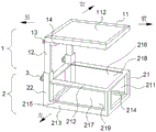
图1是本实用新型所提出的一种用于手术的头部支撑装置的一种实施例的结构示意图;1 is a schematic structural diagram of an embodiment of a head support device for surgery proposed by the present invention;
图2是本实用新型所提出的一种用于手术的头部支撑装置的另一种实施例的结构示意图;2 is a schematic structural diagram of another embodiment of a head support device for surgery proposed by the present invention;
图3是本实用新型所提出的一种手术头部支撑装置的一种实施例的使用状态结构示意图。FIG. 3 is a structural schematic diagram of an embodiment of a surgical head support device proposed by the present invention in a use state.
图中,In the figure,
1、支撑件;2、固定件;3、锁扣;4、手术台;11、支撑部;12、滑轨;13、铰链;14、支撑块;21、套装部;22、滑槽;111、第二通孔;112、凹槽;113、连接杆;211、第一通孔;212、上壁;213、左壁;214、右壁;215、下壁;216、第三通孔;217、第四通孔;218、第五通孔;219、第六通孔。1. Supporting parts; 2. Fixing parts; 3. Locking parts; 4. Operating table; 11. Supporting part; 12. Slide rail; 13. Hinge; 14. Supporting block; 21. Set part; 22. Chute; 111 , the second through hole; 112, the groove; 113, the connecting rod; 211, the first through hole; 212, the upper wall; 213, the left wall; 214, the right wall; 215, the lower wall; 216, the third through hole; 217, the fourth through hole; 218, the fifth through hole; 219, the sixth through hole.
具体实施方式Detailed ways
下面详细描述本实用新型的实施例,所述实施例的示例在附图中示出,其中至始至终相同或类似的标号表示相同或类似的元件或具有相同或类似功能的元件。下面通过参考附图描述的实施例是示例性的,旨在用于解释本实用新型,而不能理解为对本实用新型的限制。The following describes in detail the embodiments of the present invention, examples of which are illustrated in the accompanying drawings, wherein the same or similar reference numerals refer to the same or similar elements or elements having the same or similar functions throughout. The embodiments described below with reference to the accompanying drawings are exemplary, and are intended to be used to explain the present invention, but should not be construed as a limitation of the present invention.
参照图1、图2及图3,本实用新型的一种用于手术的头部支撑装置包括固定件2、支撑件1。固定件2用于与手术台4连接,使其相对手术台4固定。支撑件1在手术时位于病人的头部的上方,用于支撑覆盖在病人头部的无菌巾,防止无菌巾污染、病人憋闷及缓解病人紧张等情绪。固定件2包括套装部21、滑槽22。套装部21设置有横向的第一通孔211,用于套装在手术台4的一端。滑槽22为下端设置有终止结构的竖向滑槽22,其位于第一通孔211的一端,与套装部21固定连接。支撑件1包括支撑部11、滑轨12。支撑部11为横向板状结构,滑轨12位于支撑部11的一端,与支撑部11连接。当头部支撑装置处于使用状态时,第一通孔211套装在手术台4的一端,滑轨12与滑槽22连接,支撑部11位于病人的头部的上方,无菌巾覆盖头部时搭接在支撑部11上,避免直接覆盖在病人的头部,解决无菌巾直接覆盖病人口鼻而加快其污染、无菌巾直接覆盖在病人头部引起的憋闷、紧张等情况。且头部支撑装置通过第一通孔211套装在手术台4的一端,可以通过调整第一通孔211位于手术台4的一端的位置以适应病人头部的位置,使支撑部11位于病人头部的正上方,提高支撑部11支撑无菌巾的效果。另外,在进行永久起搏器置入手术时,由于手术位置距离头部较近,所以手术器械可以放置在支撑部11的上方,缩短大夫换取手术器械的距离及时间,提高手术效率;手术过程中,大夫也可将手臂放置在支撑部11上进行支撑,降低大夫的劳动强度,减少大夫的疲劳度,提高手术质量。Referring to FIG. 1 , FIG. 2 and FIG. 3 , a head support device for surgery according to the present invention includes a
实施例一,参照图1及图3,支撑部11为形状规则的平板状结构。优选的,支撑部11为矩形平板。滑轨12包括两个,分别位于支撑部11的左右两侧。支撑部11的一端与滑轨12的上端固定连接。在支撑部11的上侧设置有凹槽112,其与放置手术器械的放置盘的形状及尺寸适配,使放置盘能够稳固的放置在凹槽112内。优选的,在凹槽112内设置有至少一个第二通孔111,可节省材料。对应的,套装部21为长方体形状;第一通孔211为与手术台4的一端套装适配的方形通孔;滑槽22包括两个,分别位于套装部21的两侧、第一通孔211的一端,分别与两个滑轨12对应且与套装部21固定连接。使用时,第一通孔211套装在手术台4的一端,使病人的头部位于套装部21的上方;滑轨12位于滑槽22中使支撑部11位于套装部21的上方,即病人的头部的上方;滑轨12的末端抵接在滑槽22的下端的终止结构上,使支撑部11的高度固定。收回时,可将滑轨12向上提起至与滑槽22脱离并移开,方便病人躺入、换床或者起身。优选的,滑槽22的上端设置为喇叭口的形状,对滑轨12插入滑槽22具有的导向性,方便滑轨12与滑槽22的插接。
参照图1及图3,第一通孔211包括上壁212、左壁213、右壁214、下壁215。由于上壁212位于手术台4的上方,为了防止病人体感不适及节省材料,上壁212的厚度范围优选为1mm~10mm;进一步优选的,上壁212的厚度范围为2mm~6mm;且在上壁212上设置有第三通孔216,其与第一通孔211连通,使病人躺下时头部位于手术台4上,避免影响舒适感。为了节省材料,在第一通孔211的左壁213、右壁214及下壁215上分别设置有第四通孔217、第五通孔218、第六通孔219。1 and 3 , the first through
实施例二,参照图2及图3,支撑部11为规则的平板状结构。优选的,支撑部为为矩形平板。滑轨12包括两个,分别位于支撑部11的左右两侧。支撑部11的一端分别与滑轨12的上端铰接。在滑轨12的上端设置有支撑块14。当处于使用状态时,支撑部11位于支撑块14的上方,与支撑块14触接;支撑块14则承接支撑部11,使其水平放置;当收回时,支撑部11通过铰链13翻转到滑轨12的后侧,方便病人躺入、起身或者更换病床。为了使手术器械放置盘放置更加方便稳固,在支撑部11的上侧设置有凹槽112,其形状及尺寸与手术器械放置盘的形状尺寸适配,或者大于手术器械放置盘的尺寸。优选的,在凹槽112内设置有至少一个第二通孔111,节省材料。In the second embodiment, referring to FIG. 2 and FIG. 3 , the
参照图2及图3,相应的,套装部21为长方体形状,且第一通孔211为与手术台的一端套装适配的方形通孔。滑槽22包括两个,分别位于套装部21的左右两侧,且与套装部21的一端固定连接。两个滑轨12与两个滑槽22的位置对应,且两个滑轨12分别位于两个滑槽22中,且可上提滑轨12至与滑槽22脱离并移开。为了使滑轨12放入滑槽22时比较容易及方便,将滑槽22的上端设置为喇叭口的形状。2 and 3 , correspondingly, the
参照图2,为了使支撑部11与套装部21的距离可调,即支撑部11与病人头部的距离可调,还包括锁扣3。当滑轨12相对滑槽22滑动至适宜位置时,锁扣3将滑轨12与滑槽22相对固定,使支撑部11相对套装部21的距离固定。优选的,锁扣3采用螺纹孔及与螺纹孔的螺纹连接适配的螺柱的形式实现。在滑槽22的槽壁上设置有螺纹通孔。当滑轨12与滑槽22调整好位置时,旋进螺柱,使滑轨12与滑槽22相对固定;当收回时,旋出螺柱,使滑轨12相对滑槽22可滑动。方便调整支撑部11相对套装部21的距离,适应病人的头部的高度,使病人更加的舒适。Referring to FIG. 2 , in order to adjust the distance between the
为了使病人更加的舒适,第一通孔211包括上壁212、左壁213、右壁214、下壁215。上壁212的厚度范围为1mm~10mm,优选为2mm~6mm,且在上壁212上设置有第三通孔216,其与第一通孔211连通,使病人的头部不受上壁212的影响直接与手术台4接触,使病人对头部支撑装置的使用无感。为了节省材料,在左壁213、右壁214、下壁215上分别设置有第四通孔217、第五通孔218、第六通孔219。In order to make the patient more comfortable, the first through
实施例三,参照图1及图2,头部支撑装置还包括手术器械放置盘,其与支撑部11的形状及尺寸安装适配。当处于使用状态时,手术器械放置盘位于支撑部11的上方,与支撑部11连接。具体为,当支撑部11为平板状结构时,手术器械放置盘放置在支撑部11的上方;当支撑部11的上侧设置有凹槽112时,手术器械放置盘与凹槽112连接适配,其放置在凹槽112内;当凹槽112内设置有一个第二通孔111时,手术器械放置盘放置在凹槽112内、第二通孔111的上方;当凹槽112内设置有两个及两个以上第二通孔111时,凹槽112内相应的具有连接杆113或者连接部,手术器械放置盘放置在凹槽112内、连接杆113或者连接部的上方。
在本实用新型的描述中,需要理解的是,术语“上”、“下”、“前”、“后”、“左”、“右”等指示的方位或位置关系为基于附图所示的方位或位置关系,仅是为了便于描述本实用新型和简化描述,而不是指示或暗示所指的装置或元件必须具有特定的方位、以特定的方位构造和操作,因此不能理解为对本实用新型的限制。In the description of the present invention, it should be understood that the orientations or positional relationships indicated by the terms "upper", "lower", "front", "rear", "left", "right", etc. are based on those shown in the accompanying drawings. The orientation or positional relationship is only for the convenience of describing the present utility model and simplifying the description, rather than indicating or implying that the device or element referred to must have a specific orientation, be constructed and operated in a specific orientation, and therefore cannot be understood as a reference to the present utility model. limits.
此外,术语“第一”、“第二”仅用于描述目的,而不能理解为指示或暗示相对重要性或者隐含指明所指示的技术特征的数量。由此,限定有“第一”、“第二”的特征可以明示或者隐含地包括至少一个该特征。在本实用新型的描述中,“多个”的含义是至少两个,例如两个,三个等,除非另有明确具体的限定。In addition, the terms "first" and "second" are only used for descriptive purposes, and should not be construed as indicating or implying relative importance or implying the number of indicated technical features. Thus, a feature delimited with "first", "second" may expressly or implicitly include at least one of that feature. In the description of the present invention, "plurality" means at least two, such as two, three, etc., unless otherwise expressly and specifically defined.
在本实用新型中,除非另有明确的规定和限定,术语“安装”、“相连”、“连接”、“固定”等术语应做广义理解,例如,可以是固定连接,也可以是可拆卸连接,或成一体;可以是机械连接,也可以是电连接;可以是直接相连,也可以通过中间媒介间接相连,可以是两个元件内部的连通或两个元件的相互作用关系,除非另有明确的限定。对于本领域的普通技术人员而言,可以根据具体情况理解上述术语在本实用新型中的具体含义。In the present utility model, unless otherwise expressly specified and limited, the terms "installation", "connection", "connection", "fixed" and other terms should be understood in a broad sense, for example, it may be a fixed connection or a detachable connection connected, or integrated; it can be a mechanical connection or an electrical connection; it can be directly connected or indirectly connected through an intermediate medium, it can be the internal communication between two elements or the interaction between the two elements, unless otherwise clearly defined. For those of ordinary skill in the art, the specific meanings of the above terms in the present invention can be understood according to specific situations.
在本实用新型中,除非另有明确的规定和限定,第一特征在第二特征“上”或“下”可以是第一和第二特征直接接触,或第一和第二特征通过中间媒介间接接触。而且,第一特征在第二特征“之上”、“上方”和“上面”可是第一特征在第二特征正上方或斜上方,或仅仅表示第一特征水平高度高于第二特征。第一特征在第二特征“之下”、“下方”和“下面”可以是第一特征在第二特征正下方或斜下方,或仅仅表示第一特征水平高度小于第二特征。In the present invention, unless otherwise expressly specified and defined, a first feature "on" or "under" a second feature may be in direct contact with the first and second features, or the first and second features through an intermediary indirect contact. Also, the first feature being "above", "over" and "above" the second feature may mean that the first feature is directly above or obliquely above the second feature, or simply means that the first feature is level higher than the second feature. The first feature being "below", "below" and "below" the second feature may mean that the first feature is directly below or obliquely below the second feature, or simply means that the first feature has a lower level than the second feature.
在本说明书的描述中,参考术语“实施例一”、“实施例二”、中的描述意指结合该实施例或示例描述的具体特征、结构、材料或者特点包含于本实用新型实施例一或者实施例二中。在本说明书中,实施例一及实施例二中描述的具体特征、结构、材料或者特点可以在任一个或多个实施例或示例中以合适的方式结合。此外,在不相互矛盾的情况下,本领域的技术人员可以将本说明书中描述的不同实施例或示例以及不同实施例或示例的特征进行结合和组合。In the description of this specification, the reference to the terms "
尽管上面已经示出和描述了本实用新型的实施例,可以理解的是,上述实施例是示例性的,不能理解为对本实用新型的限制,本领域的普通技术人员在本实用新型的范围内可以对上述实施例进行变化、修改、替换和变型。Although the embodiments of the present invention have been shown and described above, it should be understood that the above embodiments are exemplary and should not be construed as limitations of the present invention, and those of ordinary skill in the art are within the scope of the present invention Variations, modifications, substitutions and variations can be made to the above-described embodiments.
Claims (10)
Priority Applications (1)
| Application Number | Priority Date | Filing Date | Title |
|---|---|---|---|
| CN201921204570.7U CN211381832U (en) | 2019-07-29 | 2019-07-29 | A head support device for surgery |
Applications Claiming Priority (1)
| Application Number | Priority Date | Filing Date | Title |
|---|---|---|---|
| CN201921204570.7U CN211381832U (en) | 2019-07-29 | 2019-07-29 | A head support device for surgery |
Publications (1)
| Publication Number | Publication Date |
|---|---|
| CN211381832U true CN211381832U (en) | 2020-09-01 |
Family
ID=72229770
Family Applications (1)
| Application Number | Title | Priority Date | Filing Date |
|---|---|---|---|
| CN201921204570.7U Expired - Fee Related CN211381832U (en) | 2019-07-29 | 2019-07-29 | A head support device for surgery |
Country Status (1)
| Country | Link |
|---|---|
| CN (1) | CN211381832U (en) |
Cited By (1)
| Publication number | Priority date | Publication date | Assignee | Title |
|---|---|---|---|---|
| CN112690989A (en) * | 2021-01-12 | 2021-04-23 | 蚌埠医学院第一附属医院(蚌埠医学院附属肿瘤医院) | A surgical hood and surgical bed |
-
2019
- 2019-07-29 CN CN201921204570.7U patent/CN211381832U/en not_active Expired - Fee Related
Cited By (1)
| Publication number | Priority date | Publication date | Assignee | Title |
|---|---|---|---|---|
| CN112690989A (en) * | 2021-01-12 | 2021-04-23 | 蚌埠医学院第一附属医院(蚌埠医学院附属肿瘤医院) | A surgical hood and surgical bed |
Similar Documents
| Publication | Publication Date | Title |
|---|---|---|
| CN212037770U (en) | Orthopedic traction frame device | |
| CN209984232U (en) | Adjustable B-ultrasonic examining table | |
| CN210962725U (en) | Neonate position adjusting device | |
| CN208641093U (en) | A kind of nursing mattress | |
| CN204501449U (en) | An ophthalmic operating bed | |
| CN217611448U (en) | Orthopedics arthroscopic surgery auxiliary device | |
| CN111568684A (en) | A neurosurgery head positioning support device | |
| CN212547568U (en) | Fixed pillow of ophthalmic surgery | |
| CN221154276U (en) | Skull traction auxiliary structure | |
| CN203001353U (en) | Body posture neck collar used in head-and-neck operation | |
| CN206342634U (en) | A kind of medical pillow with neck of patient with cervical Spondylopathy | |
| CN218979587U (en) | A painless gastroenteroscope position fixer | |
| CN221013255U (en) | Upper limb support device | |
| CN211634133U (en) | An operating bed for spinal surgery in prone position | |
| CN218338661U (en) | Arm head supporting bracket | |
| CN218923043U (en) | Dual-purpose bed table for ophthalmology | |
| CN204337233U (en) | Multifunction surgical puts palm | |
| CN217039353U (en) | A multifunctional bedside table | |
| CN217430399U (en) | Support convenient to adjust for clinical hip joint operation of orthopedics | |
| CN211095715U (en) | Interventional operation bracket | |
| CN223041757U (en) | A nursing surgical dressing device | |
| CN222265669U (en) | Posture pad suitable for prone position of female operation patient | |
| CN206025784U (en) | Electric bed | |
| CN220917609U (en) | Nursing stretcher | |
| CN109303957A (en) | A kind of pediatric anesthesia stabilization hand fixing device |
Legal Events
| Date | Code | Title | Description |
|---|---|---|---|
| GR01 | Patent grant | ||
| GR01 | Patent grant | ||
| CF01 | Termination of patent right due to non-payment of annual fee |
Granted publication date: 20200901 |
|
| CF01 | Termination of patent right due to non-payment of annual fee |