CN211377117U - Power track, socket and track power system - Google Patents
Power track, socket and track power system Download PDFInfo
- Publication number
- CN211377117U CN211377117U CN202020138915.XU CN202020138915U CN211377117U CN 211377117 U CN211377117 U CN 211377117U CN 202020138915 U CN202020138915 U CN 202020138915U CN 211377117 U CN211377117 U CN 211377117U
- Authority
- CN
- China
- Prior art keywords
- socket
- power track
- track
- conductor
- receptacle
- Prior art date
- Legal status (The legal status is an assumption and is not a legal conclusion. Google has not performed a legal analysis and makes no representation as to the accuracy of the status listed.)
- Active
Links
- 239000004020 conductor Substances 0.000 claims abstract description 53
- 238000003780 insertion Methods 0.000 claims description 20
- 230000037431 insertion Effects 0.000 claims description 20
- RNFJDJUURJAICM-UHFFFAOYSA-N 2,2,4,4,6,6-hexaphenoxy-1,3,5-triaza-2$l^{5},4$l^{5},6$l^{5}-triphosphacyclohexa-1,3,5-triene Chemical group N=1P(OC=2C=CC=CC=2)(OC=2C=CC=CC=2)=NP(OC=2C=CC=CC=2)(OC=2C=CC=CC=2)=NP=1(OC=1C=CC=CC=1)OC1=CC=CC=C1 RNFJDJUURJAICM-UHFFFAOYSA-N 0.000 claims description 4
- 239000003292 glue Substances 0.000 claims 2
- 230000009286 beneficial effect Effects 0.000 abstract description 2
- 230000002349 favourable effect Effects 0.000 abstract description 2
- 239000002390 adhesive tape Substances 0.000 description 4
- 238000010586 diagram Methods 0.000 description 2
- 230000000694 effects Effects 0.000 description 2
- 239000000463 material Substances 0.000 description 2
- 230000002265 prevention Effects 0.000 description 2
- 229910000838 Al alloy Inorganic materials 0.000 description 1
- RYGMFSIKBFXOCR-UHFFFAOYSA-N Copper Chemical compound [Cu] RYGMFSIKBFXOCR-UHFFFAOYSA-N 0.000 description 1
- 238000010276 construction Methods 0.000 description 1
- 208000010247 contact dermatitis Diseases 0.000 description 1
- 229910052802 copper Inorganic materials 0.000 description 1
- 239000010949 copper Substances 0.000 description 1
- 239000000428 dust Substances 0.000 description 1
- 238000010891 electric arc Methods 0.000 description 1
- 239000003063 flame retardant Substances 0.000 description 1
- 239000011810 insulating material Substances 0.000 description 1
- 229910052751 metal Inorganic materials 0.000 description 1
- 239000002184 metal Substances 0.000 description 1
- 238000012986 modification Methods 0.000 description 1
- 230000004048 modification Effects 0.000 description 1
- 229920003023 plastic Polymers 0.000 description 1
- 239000004033 plastic Substances 0.000 description 1
- 229920000915 polyvinyl chloride Polymers 0.000 description 1
- 239000004800 polyvinyl chloride Substances 0.000 description 1
- 239000010935 stainless steel Substances 0.000 description 1
- 229910001220 stainless steel Inorganic materials 0.000 description 1
- XLYOFNOQVPJJNP-UHFFFAOYSA-N water Substances O XLYOFNOQVPJJNP-UHFFFAOYSA-N 0.000 description 1
Images




Landscapes
- Connector Housings Or Holding Contact Members (AREA)
Abstract
The utility model discloses an electric power track, socket and track electric power system belongs to electric power connecting device technical field. The power track comprises a shell, the top of the shell is an inclined plane, an opening is formed in the inclined plane along the length direction of the power track, the opening is used for inserting a socket into an area extending inside the shell, and a conductor is arranged inside the shell along the length direction of the power track. Through the inclined plane guide at electric power track top, be favorable to slipping the inserted sheet of socket to the opening, convenience of customers inserts electric power track's inside with the socket to reach the beneficial effect that convenient user used.
Description
Technical Field
The utility model relates to a power equipment technical field, in particular to electric power connecting device technical field specifically indicates an electric power track, socket and track electric power system.
Background
In daily life, various electric appliances used by people need sockets for supplying power, so that the sockets are often arranged at a plurality of positions in a room, but the environment is disordered by arranging the sockets at different positions. The existing power supply connecting device comprises a power track and a socket, and when the power supply connecting device is used, the socket is inserted into the power track so as to supply power to an electric appliance through the socket; when the socket is not needed to be used, the socket is pulled out of the power track. However, the surface of the socket of the power track is perpendicular to the two adjacent surfaces, the socket needs to be found before the socket is inserted into the power track, and the socket is hidden in an environment with insufficient light or the power track with high waterproof and dustproof performance, which causes inconvenience for a user to insert the socket into the power track.
For example, as shown in fig. 1, a power rail and socket of the prior art, a socket 302 is inserted on a power rail 301, and the power rail 301 is fixed on a desktop 304 by a fixing bracket 303. Wherein the top surface 301a of the power rail 301 is planar, in particular the top surface 301a of the power rail 301 is perpendicular to the two adjacent surfaces 301b, 301 c.
SUMMERY OF THE UTILITY MODEL
In order to overcome the problems, the utility model discloses an aspect provides an electric power track, which comprises a housin, the top of casing is the inclined plane, follow on the inclined plane electric power track length direction is equipped with the opening, follows the opening to the position is inserted for the socket in the inside region that extends of casing, the casing is inside to be followed electric power track length direction is equipped with the conductor.
Further, the back of the shell is higher than the front of the shell, the top extends from the top end of the back to the top end of the front, and the back of the shell is provided with a mounting structure.
Furthermore, the power track further comprises an elastic supporting piece, the elastic supporting piece abuts against the inner wall of the shell, the conductor is fixed on the elastic supporting piece, and the conductor is located at a position close to the socket insertion position.
Further, the elastic supporting piece is of a flame-retardant structure.
Further, the number of the conductors is at least two, and the at least two conductors are distributed on two sides of the socket insertion position.
Further, be equipped with two cylindricality adhesive tapes along the opening in the casing, two cylindricality adhesive tapes are contradicted each other.
The utility model also provides a socket, which comprises a socket main body, a bevel board and an inserting piece, wherein the front of the socket main body is provided with a jack; the inclined plane plate is connected to the socket main body, is positioned behind the socket main body and is inclined relative to the socket main body; the inserted sheet is fixed in on the inclined plane board, just be equipped with the conductor contact on the inserted sheet.
Further, the inclined plane plate inclines upwards relative to the socket main body, and the insertion sheet is fixed on the lower side of the inclined plane plate.
Another aspect of the utility model provides a track electric power system, include the utility model discloses an electric power track with the utility model discloses a socket, the socket passes through the inserted sheet insert in electric power is orbital the position is inserted to the socket, the conductor contact is with corresponding the conductor contact.
Further, the conductor is located proximate to the receptacle insertion site when the receptacle is not inserted in the power track; when the socket is inserted into the power track, the conductor contact contacts the corresponding conductor and presses the elastic supporting piece against the inner wall of the shell.
According to the above, the power track of the present invention comprises a housing, the top of the housing is an inclined plane, an opening is provided on the inclined plane along the length direction of the power track, a socket is inserted into the area extending from the opening to the inside of the housing, and a conductor is provided inside the housing along the length direction of the power track. Through the inclined plane guide at electric power track top, be favorable to slipping the inserted sheet of socket to the opening, convenience of customers inserts electric power track's inside with the socket to reach the beneficial effect that convenient user used.
Drawings
FIG. 1 is a schematic diagram of a prior art power track and receptacle;
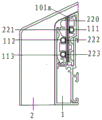
fig. 2 is a schematic diagram of a receptacle inserted into a power track according to an embodiment of the present invention;
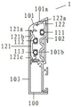
fig. 3 is a perspective view of an electric power track according to an embodiment of the present invention;
fig. 4 is a right side view of an electric power track according to an embodiment of the present invention;
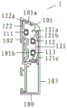
fig. 5 is a left side view of an electric power track according to an embodiment of the present invention;
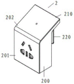
fig. 6 is a perspective view of a socket according to an embodiment of the present invention;
fig. 7 is a right side view of a receptacle according to an embodiment of the present invention;
fig. 8 is a left side view of a receptacle according to an embodiment of the present invention;
description of the symbols:
1-an electric power track; 100-a housing; 101-a housing top; 101 a-opening; 101 b-socket insertion position; 102-housing back; 103-housing front; 111. 112, 113-conductors; 121. 122-a resilient support; 121a, 121b, 121c, 122 a-voids; 2-a socket; 200-a socket body; 201-front of socket; 202-a socket top; 210-a bevel panel; 220-plug sheet; 221. 222, 223-conductor contacts.
Detailed Description
In order to make the objects, technical solutions and advantages of the present invention clearer, embodiments of the present invention will be described in further detail below with reference to the accompanying drawings.
Referring to fig. 2, a track power system according to an embodiment of the present invention includes a power track 1 and a receptacle 2, the receptacle 2 is inserted into the power track 1 through an insert 220, wherein conductor contacts 221, 222, 223 on the receptacle 2 are respectively contacted with conductors 111, 112, 113 on the corresponding power track.
Specifically, the power rail 1 in the present embodiment is a perspective view of the power rail 1 when the receptacle 2 is not inserted, as shown in fig. 3, and the power rail 1 is substantially elongated as a whole, and has its upper and lower surfaces parallel to each other. If the position of the conductor in the power track 1 is not affected, the shape of the lower surface thereof may not be limited. Furthermore, the power track 1 of the present embodiment includes a housing 100, which may be divided into a front cover plate and a rear cover plate, and may be fixed by structural caulking, and may be made of metal, such as aluminum alloy or stainless steel. The top 101 of the housing 100 is a slope having an opening 101a along the length of the power track 1. As shown in fig. 4 or 5, the area extending from the opening 101a to the inside of the housing 100 is a socket insertion site 101 b. When inserting the receptacle 2 into the power track 1, the blade 220 of the receptacle 2 is guided by the inclined surface of the top 101 of the power track 1 to slide to the opening 101a, so that the user can insert the blade 220 of the receptacle 2 into the receptacle insertion site 101 b.
Furthermore, at least two conductors, such as copper conductive tubes, are disposed inside the housing 100 along the length direction of the power track 1, and the highest load 50A is disposed. These conductors may be located on the same side of the socket insertion site 101b or may be distributed on different sides for connection to house wires. In the embodiment, three conductors 111, 112, and 113 are disposed in the power rail 1, the conductors 112 and 113 are located at the left side of the socket insertion site 101b, and the conductor 111 is located at the right side of the socket insertion site 101b, so that the conductor 111 is connected to the live wire, thereby effectively preventing the generation of electric arc.
Preferably, the back side 102 of the housing 100 is provided with mounting structures, such as snap-in structures or screw connection structures or the like, for fixing the power track 1 to a wall or furniture. Also, the back surface 102 of the housing 100 is higher than the front surface 103 of the housing 100, and the top 101 extends from the top end of the back surface 102 to the top end of the front surface 103, in such a manner that the top 101 shows the opening 101a toward the user, thereby further facilitating the user's use.
Preferably, the power track 1 may further include an elastic support abutting against an inner wall of the housing 100, the conductors 111, 112, 113 being fixed to the elastic support and being located near the socket insertion site 101 b. The number of the elastic supporting members is set according to the distribution positions of the conductors 111, 112, 113, and if the conductors are located on the same side, one elastic supporting member may be provided. Since the conductors 111, 112, 113 in this embodiment are distributed on two sides, the elastic support 121 is disposed to fix the conductors 112, 113, and the elastic support 122 is disposed to fix the conductor 111. When the blades 220 of the socket 2 are inserted into the socket insertion site 101b, the stability of the contact between the conductors 111, 112, 113 and the conductor contacts 221, 222, 223 can be increased under the force of the elastic supports 121, 122. Wherein, elasticity support piece can select for use self to have the flexible function of elasticity's structure, for example insulating material's spring structure, also can adopt the structure that can deform and kick-back, for example plastic construction. In this embodiment, pvc (polyvinyl chloride) is used as the material of the elastic supporting members 121 and 122.
The elastic supporting member 121 abuts against the left inner wall of the housing 100, and gaps 121a, 121b, and 121c are respectively left between the end, upper portion, and lower portion of the elastic supporting member 121 and the inner wall of the housing 100. The elastic support 122 abuts against the inner wall of the right side of the housing 100, and a gap 122a is left between the elastic support 122 and the inner wall of the housing 100. The end of the elastic support 122 may be provided with a protrusion located at the middle of the opening 101 a. When the socket 2 is not inserted, the bulge plays a role in dust prevention and water prevention; when the socket 2 is inserted, the projection moves downward away from the opening 101a, and at this time, the elastic support 122 is deformed, and the bent portion thereof moves toward the gap 122 a. At this time, the conductor contact on the socket 2 contacts with the corresponding conductor on the power rail 1, and presses the elastic support members 121 and 122 against the inner wall of the housing 100. Specifically, as shown in fig. 2, the conductor contacts 221, 222, 223 are in contact with the conductors 111, 112, 113, respectively. At this time, the elastic supporting member 121 is deformed such that the end thereof extends into the space 121a, and the upper and lower portions of the elastic supporting member 121 are moved into the spaces 121b and 121c, respectively, due to the deformation. In this way, the elastic supporting members 121 exert elastic effects, which can increase the contact stability of each conductor contact and the corresponding conductor, increase the contact sensitivity, and enable the left and right elastic supporting members to retract and pop up.
Preferably, the elastic supporting members 121 and 122 may be provided with a flame retardant structure, as shown in fig. 4, the conductors are isolated from each other, and the flame retardant material fixes the conductors in a semi-surrounding manner, thereby increasing the safety of users.
Preferably, two cylindrical adhesive tapes are arranged in the shell 1 along the opening 101a, and the two cylindrical adhesive tapes are mutually abutted, so that the waterproof and dustproof effects can be achieved.
Specifically, as can be seen from fig. 6, the socket 2 of the present embodiment includes a socket body 200, a bevel board 210 and a plug 220, wherein the front 201 of the socket body 200 is provided with a plug hole. The bevel plate 210 is coupled to the socket body 200. In this embodiment, the bevel board 210 is connected to the top 202 of the socket body 200 as a single panel, but the invention is not limited to this, for example, the bevel board 210 may be connected to the back of the socket body 200, and the bevel board 210 is located behind the socket body 200, so as to tilt the bevel board 210 relative to the socket body 200. In addition, as shown in fig. 7 or 8, the insertion sheet 220 is fixed on the inclined plane 210, and the insertion sheet 220 is provided with conductor contacts 221, 222, 223.
Further, the slope plate 210 is inclined upward with respect to the socket body 200, and the insertion piece 220 is fixed to a lower side of the slope plate 210. The blades 220 are guided by the inclined surface of the top 101 of the power rail 1, so that the receptacle 2 can be inserted into the power rail 1 more conveniently.
When the receptacle 2 is inserted into the power track 1, a portion of the thickness of the power track 1 is sandwiched between the back of the receptacle 2 and the blades 220. Preferably, the ramp plate 210 of the receptacle 2 is inclined at an angle corresponding to the top surface 101 of the power rail 1, so that the connection of the receptacle 2 to the power rail 1 is more stable.
Further, the distance from the socket insertion site 101b of the power track 1 of the present embodiment to the housing front face 103 is kept constant in the length direction of the power track 1. The receptacle 2 can then be moved along the length of the power track 1 for more convenient use by the user.
In addition, the number of the conductor contacts on the socket 2 in this embodiment is not limited, and may be specifically set according to actual requirements.
In this specification, the invention has been described with reference to specific embodiments thereof. It will, however, be evident that various modifications and changes may be made thereto without departing from the broader spirit and scope of the invention. The specification and drawings are, accordingly, to be regarded in an illustrative rather than a restrictive sense.
Claims (10)
1. The power track is characterized by comprising a shell, wherein the top of the shell is an inclined plane, an opening is formed in the inclined plane along the length direction of the power track, a socket inserting position is formed in an area extending from the opening to the inside of the shell, and a conductor is arranged in the shell along the length direction of the power track.
2. The power track of claim 1, wherein the back of the housing is higher than the front of the housing, the top extends from a top of the back to a top of the front, and the back of the housing is provided with a mounting structure.
3. The power track of claim 1, further comprising a resilient support abutting against an inner wall of the housing, wherein the conductor is fixed to the resilient support and is located near the socket insertion site.
4. An electric power track according to claim 3, characterized in that the resilient support is provided as a flame-retardant structure.
5. The power track of claim 1, wherein the number of conductors is at least two, the at least two conductors being distributed on both sides of the socket insertion site.
6. The power track of claim 5, wherein two cylindrical strips of glue are provided within the housing along the opening, the two cylindrical strips of glue abutting each other.
7. A socket, comprising:
the socket comprises a socket main body, wherein jacks are arranged in the front of the socket main body;
the inclined plane plate is connected to the socket main body, is positioned behind the socket main body and is inclined relative to the socket main body;
the inserted sheet, the inserted sheet is fixed in on the inclined plane board, just be equipped with the conductor contact on the inserted sheet.
8. The receptacle of claim 7 wherein said ramp panel is angled upward relative to said receptacle body and said tab is secured to the underside of said ramp panel.
9. A rail power system, comprising: the power track of any one of claims 1 to 6, and the receptacle of claim 7 or 8, the receptacle being inserted into the receptacle insertion site of the power track by the blades, the conductor contacts being in contact with the corresponding conductors.
10. The track power system of claim 9, wherein the power track further comprises a resilient support abutting against an inner wall of the housing, the conductor being secured to the resilient support; the conductor is located proximate to the receptacle insertion site when the receptacle is not inserted in the power track; when the socket is inserted into the power track, the conductor contact contacts the corresponding conductor and presses the elastic supporting piece against the inner wall of the shell.
Priority Applications (1)
| Application Number | Priority Date | Filing Date | Title |
|---|---|---|---|
| CN202020138915.XU CN211377117U (en) | 2020-01-21 | 2020-01-21 | Power track, socket and track power system |
Applications Claiming Priority (1)
| Application Number | Priority Date | Filing Date | Title |
|---|---|---|---|
| CN202020138915.XU CN211377117U (en) | 2020-01-21 | 2020-01-21 | Power track, socket and track power system |
Publications (1)
| Publication Number | Publication Date |
|---|---|
| CN211377117U true CN211377117U (en) | 2020-08-28 |
Family
ID=72150812
Family Applications (1)
| Application Number | Title | Priority Date | Filing Date |
|---|---|---|---|
| CN202020138915.XU Active CN211377117U (en) | 2020-01-21 | 2020-01-21 | Power track, socket and track power system |
Country Status (1)
| Country | Link |
|---|---|
| CN (1) | CN211377117U (en) |
Cited By (1)
| Publication number | Priority date | Publication date | Assignee | Title |
|---|---|---|---|---|
| CN111146658A (en) * | 2020-01-21 | 2020-05-12 | 上海酷仑智能科技有限公司 | Power Tracks, Outlets and Track Power Systems |
-
2020
- 2020-01-21 CN CN202020138915.XU patent/CN211377117U/en active Active
Cited By (1)
| Publication number | Priority date | Publication date | Assignee | Title |
|---|---|---|---|---|
| CN111146658A (en) * | 2020-01-21 | 2020-05-12 | 上海酷仑智能科技有限公司 | Power Tracks, Outlets and Track Power Systems |
Similar Documents
| Publication | Publication Date | Title |
|---|---|---|
| CN111146658A (en) | Power Tracks, Outlets and Track Power Systems | |
| US7670156B2 (en) | Electrical connector | |
| AU2010357631B2 (en) | Electrical power distribution track system | |
| CN113675685A (en) | A track socket system | |
| CN112484001A (en) | Embedded goods shelves get electric system | |
| CN216289377U (en) | Track socket capable of being flexibly adapted | |
| CN212204115U (en) | Track lamp assembly | |
| CN220172425U (en) | Adapter and track socket | |
| CN203690564U (en) | Electric connector | |
| CN212005263U (en) | Rail lamp system | |
| JPS5846543Y2 (en) | Electrical connectors for circuit boards | |
| CN217036238U (en) | Power taking system for goods shelf | |
| CN210430312U (en) | Sliding type socket guide rail mounting structure | |
| CN222395218U (en) | A power rail with fool-proof function | |
| CN219106700U (en) | Reverse-plug type power guide rail | |
| CN221375595U (en) | Welding-free lamp strip | |
| CN220107126U (en) | Power supply rail | |
| CN221574374U (en) | Hidden intelligent socket backboard | |
| CN219800762U (en) | Grafting structure and 1U surge protector | |
| CN221009390U (en) | Socket structure | |
| CN2277574Y (en) | Socket connector | |
| CN223693404U (en) | Multi-plug socket | |
| CN216698981U (en) | Triangular multifunctional socket | |
| CN221262735U (en) | Be used for orbital quick binding post of lamp decoration and terminal box | |
| CN217589657U (en) | Embedded socket and have its home equipment |
Legal Events
| Date | Code | Title | Description |
|---|---|---|---|
| GR01 | Patent grant | ||
| GR01 | Patent grant |