CN211369699U - electric sunshade - Google Patents
electric sunshade Download PDFInfo
- Publication number
- CN211369699U CN211369699U CN201921669126.2U CN201921669126U CN211369699U CN 211369699 U CN211369699 U CN 211369699U CN 201921669126 U CN201921669126 U CN 201921669126U CN 211369699 U CN211369699 U CN 211369699U
- Authority
- CN
- China
- Prior art keywords
- toothed belt
- sleeve
- driving wheel
- tarpaulin
- power unit
- Prior art date
- Legal status (The legal status is an assumption and is not a legal conclusion. Google has not performed a legal analysis and makes no representation as to the accuracy of the status listed.)
- Active
Links
Images






Landscapes
- Walking Sticks, Umbrellas, And Fans (AREA)
Abstract
Description
技术领域technical field
本实用新型涉及遮阳伞领域技术,尤其是指一种电动遮阳伞,其主要适用于车载使用。The utility model relates to the technology in the field of sunshades, in particular to an electric sunshade, which is mainly suitable for vehicle use.
背景技术Background technique
随着经济的发展,和人民生活水平的提高,私家车作为一种高级代步工具走进千家万户。日常生活中,汽车经常会停放在露天环境中,夏天高温暴晒后,会使车内温度高达70摄氏度以上,开车前须通风降温一段时间,同时造成车内饰品加速老化并释放大量有气体,为了对汽车进行保护,一般都会利用遮阳伞或者车衣进行防护和降温。With the development of the economy and the improvement of people's living standards, private cars have entered thousands of households as an advanced means of transportation. In daily life, cars are often parked in the open air. After high temperature exposure in summer, the temperature inside the car will reach above 70 degrees Celsius. Before driving, it is necessary to ventilate and cool down for a period of time. At the same time, it will cause the interior accessories to accelerate aging and release a large amount of gas. In order to To protect the car, umbrellas or car clothing are generally used for protection and cooling.
但是,现有的遮阳伞,大多采用手动收展的方式设计,或者采用纯机械方式设计;而此种类型的遮阳伞其结构普遍存在结构复杂,整体的体积大;不仅在收展时变得尤为不便,还不便于收纳,并不符合当今的小型化发展趋势;且其结构本身复杂,使用的稳定性和可靠性也较差。However, most of the existing sunshades are designed by manual retraction or purely mechanical design; however, the structure of this type of sunshade is generally complicated and the overall volume is large; It is particularly inconvenient, not easy to store, and does not conform to the current miniaturization development trend; and its structure itself is complex, and the stability and reliability of use are also poor.
实用新型内容Utility model content
有鉴于此,本实用新型针对现有技术存在之缺失,其主要目的是提供一种结构简单、零部件少、体积小、便于收纳的电动遮阳伞。In view of this, the main purpose of the present invention is to provide an electric sunshade with simple structure, few parts, small volume and convenient storage.
为实现上述目的,本实用新型采用如下之技术方案:To achieve the above object, the present invention adopts the following technical scheme:
一种电动遮阳伞,包括有An electric sunshade includes
一伸缩杆,包括有至少两节同轴的套管构成,且相邻套管可滑动伸缩;a telescopic rod, which is composed of at least two coaxial sleeves, and the adjacent sleeves can be slidably telescopic;
一驱动机构,包括有至少一齿形带、一动力单元和一驱动件;所述齿形带的一端连接套管,动力单元驱动驱动件转动时牵引齿形带使套管可选择性地缩回或伸出。A driving mechanism includes at least one toothed belt, a power unit and a driving member; one end of the toothed belt is connected to a sleeve, and when the power unit drives the driving member to rotate, the toothed belt is pulled so that the sleeve can be selectively retracted back or out.
一篷布,连接于套管;随套管的伸出展开篷布或缩回收回篷布。A tarpaulin is connected to the casing; the tarpaulin is unfolded or retracted with the extension of the casing.
作为一种优选方案:所述齿形带卷绕式位于驱动件的外周,该齿形带的内侧具有沿其延伸方向设置第一啮合齿;所述驱动件设有第二啮合齿,该第一啮合齿配合于第二啮合齿;所述动力单元连接驱动件,驱动件转动时牵引齿形带使套管可选择性地缩回或伸出。As a preferred solution: the toothed belt is wound on the outer circumference of the driving member, and the inner side of the toothed belt has first meshing teeth arranged along its extending direction; the driving member is provided with second meshing teeth, the A meshing tooth is matched with the second meshing tooth; the power unit is connected with the driving member, and when the driving member rotates, the toothed belt is pulled so that the sleeve can be retracted or extended selectively.
作为一种优选方案:所述驱动件包括有上驱动轮和下驱动轮,该下驱动轮设有离合结构,该上驱动轮可转动安装于离合结构;所述第二啮合齿设于上驱动轮,所述动力单元连接下驱动轮;所述上驱动轮随下驱动轮同步转动,最大伸出量和/或最大回缩量时,所述下驱动轮的离合结构脱离上驱动轮,以形成下驱动轮相对上驱动轮转动之空转状态。As a preferred solution: the driving member includes an upper driving wheel and a lower driving wheel, the lower driving wheel is provided with a clutch structure, and the upper driving wheel can be rotatably installed on the clutch structure; the second meshing teeth are provided on the upper driving wheel The power unit is connected to the lower driving wheel; the upper driving wheel rotates synchronously with the lower driving wheel, and when the maximum extension and/or maximum retraction amount is reached, the clutch structure of the lower driving wheel is separated from the upper driving wheel to An idling state in which the lower driving wheel rotates relative to the upper driving wheel is formed.
作为一种优选方案:所述驱动件上方设有用于收纳齿形带的收纳件,所述齿形带收回时容置于齿形带收纳件中。As a preferred solution, a storage member for accommodating the toothed belt is arranged above the driving member, and the toothed belt is accommodated in the toothed belt storage member when retracted.
作为一种优选方案:所述驱动件的侧旁设有一压紧轮,所述齿形带位于该压紧轮和驱动件之间。As a preferred solution, a pressing wheel is provided on the side of the driving member, and the toothed belt is located between the pressing wheel and the driving member.
作为一种优选方案:所述齿形带可选择性容置于套管内,且该齿形带的端部连接最末端的套管。As a preferred solution, the toothed belt can be selectively accommodated in the sleeve, and the end of the toothed belt is connected to the endmost sleeve.
作为一种优选方案:进一步地包括有一机壳,该机壳由底壳和上盖构成;所述驱动机构和最首端的一套管设于机壳中。As a preferred solution: it further includes a casing, the casing is composed of a bottom casing and an upper cover; the driving mechanism and the first sleeve are arranged in the casing.
作为一种优选方案:进一步地包括有一收纳袋,所述机壳和篷布可选择性收纳于收纳袋中。As a preferred solution: a storage bag is further included, and the cabinet and the tarpaulin can be selectively stored in the storage bag.
作为一种优选方案:所述收纳袋底部安装有一底座,该底座设有导柱;所述机壳底部设有筒体,该筒体可移动安装于导柱。As a preferred solution, a base is installed at the bottom of the storage bag, and the base is provided with a guide post; the bottom of the casing is provided with a cylinder, and the cylinder can be movably installed on the guide post.
作为一种优选方案:所述底座的底部显露于收纳袋的底部,该底座的底部还设有吸盘。As a preferred solution: the bottom of the base is exposed at the bottom of the storage bag, and the bottom of the base is also provided with a suction cup.
本实用新型与现有技术相比具有明显的优点和有益效果,具体而言,由上述技术方案可知:通过设置的伸缩杆、驱动机构和篷布,伸缩杆能够通过驱动机构驱动其伸出或者缩回,由此可以使连接伸缩杆的篷布展开或者收回;相较于以往需要手动收展的遮阳伞而言,其使用更加方便;Compared with the prior art, the utility model has obvious advantages and beneficial effects. Specifically, it can be seen from the above technical solutions that the telescopic rod can be driven by the driving mechanism to extend or extend through the provided telescopic rod, the driving mechanism and the tarpaulin. Retracted, so that the tarpaulin connected to the telescopic rod can be unfolded or retracted; compared with the previous sunshades that need to be manually retracted, it is more convenient to use;
并且,该驱动机构主要够动力单元和齿形带两个关键部件构成,齿形带连接伸缩杆的套管,利用动力单元牵引齿形带即完成套管缩回或者伸出,这样将篷布连接套管就能够使篷布随着套管缩回收回篷布或伸出展开篷布;由此可见,驱动机构的结构简单,零部件设置巧妙合理,能够降低自动遮阳伞的体积和重量,使收纳和使用更加方便,符合当今的小型化发展趋势,利于推广应用;同时结构简单的电动遮阳伞,可以提高使用时的稳定性和可靠性。In addition, the drive mechanism is mainly composed of two key components, the power unit and the toothed belt. The toothed belt is connected to the sleeve of the telescopic rod, and the power unit is used to pull the toothed belt to complete the retraction or extension of the sleeve, so that the tarpaulin can be retracted or extended. By connecting the sleeve, the tarpaulin can be retracted back to the tarpaulin or extended to unfold the tarpaulin with the sleeve; it can be seen that the structure of the driving mechanism is simple, the parts are set ingeniously and reasonably, and the volume and weight of the automatic sunshade can be reduced. It makes storage and use more convenient, conforms to the current miniaturization development trend, and is conducive to popularization and application; at the same time, the electric sunshade with a simple structure can improve the stability and reliability during use.
为更清楚地阐述本实用新型的结构特征和功效,下面结合附图与具体实施例来对本实用新型进行详细说明。In order to illustrate the structural features and functions of the present invention more clearly, the present invention will be described in detail below with reference to the accompanying drawings and specific embodiments.
附图说明Description of drawings
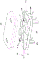
图1是本实用新型之较佳实施例的电动伸缩杆的立体结构示意图。FIG. 1 is a schematic three-dimensional structure diagram of an electric telescopic rod according to a preferred embodiment of the present invention.
图2是本实用新型之较佳实施例的电动伸缩杆打开上盖的结构示意图。2 is a schematic structural diagram of the electric telescopic rod opening the upper cover according to the preferred embodiment of the present invention.
图3是本实用新型之较佳实施例的电动伸缩杆的分解图。FIG. 3 is an exploded view of the electric telescopic rod according to the preferred embodiment of the present invention.
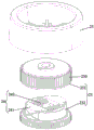
图4是图3 A处的放大示意图。FIG. 4 is an enlarged schematic view at A of FIG. 3 .
图5是本实用新型之较佳实施例的驱动件的结构示意图。FIG. 5 is a schematic structural diagram of a driving member of a preferred embodiment of the present invention.
图6是图5的驱动件的分解图。FIG. 6 is an exploded view of the drive member of FIG. 5 .
图7是图5的驱动件的剖视图。FIG. 7 is a cross-sectional view of the driver of FIG. 5 .
图8是本实用新型之较佳实施例的伸缩杆伸出的状态示意图。FIG. 8 is a schematic diagram of a state in which the telescopic rod is extended according to the preferred embodiment of the present invention.
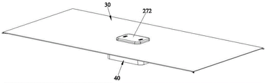
图9是本实用新型之较佳实施例的篷布张开的状态示意图。FIG. 9 is a schematic diagram of the state where the tarpaulin is opened according to the preferred embodiment of the present invention.
图10是图9的另一角度示意图。FIG. 10 is another perspective view of FIG. 9 .
附图标识说明:Description of drawings:
10、伸缩杆 11、套管10. Telescopic
20、驱动机构 21、齿形带20.
211、第一啮合齿 22、动力单元211, the first meshing tooth 22, the power unit
221、电机 222、减速齿轮221,
23、驱动件 230、第二啮合齿23. Driving
231、上驱动轮 232、下驱动轮231, upper
24、离合结构 241弹块24. Clutch
242、弹簧 25、收纳件242,
251、仓体 26、压紧轮251,
27、机壳 271、底壳27.
272、上盖 273、筒体272,
28、衔接齿轮 29、PCB控制板28. Connecting gears 29. PCB control board
200、电池 30、篷布200,
40、收纳袋 411、导柱40.
412、吸盘。412. Suction cups.
具体实施方式Detailed ways
请参照图1至图10所示,其显示出了本实用新型之较佳实施例的具体结构,是一种电动遮阳伞,包括有伸缩杆10、驱动机构20和篷布30。Please refer to FIGS. 1 to 10 , which show the specific structure of a preferred embodiment of the present invention, which is an electric sunshade, including a
所述伸缩杆10包括有至少两节同轴的套管11构成,且相邻的套管11可欢动伸缩。所述驱动机构20包括有至少一齿形带21、一动力单元22和一驱动件23;其中,所述齿形带21卷绕式位于驱动件23的外周,该齿形带21的内侧具有沿其延伸方向设置第一啮合齿211;所述驱动件23设有第二啮合齿230,该第一啮合齿211配合于第二啮合齿230;所述动力单元22连接驱动件23,驱动件23转动时牵引齿形带21使套管11可选择性地缩回或伸出。由此可见,此种电动伸缩杆的结构非常简单,相较于传统的电动伸缩杆结构而言,其结构更加简单,伸缩杆10的收回之后的整体体积小,重量轻,非常适合应用于遮阳伞等产品上;并且结构简单的电动伸缩杆其伸缩效果更佳容易实现,其使用时的稳定性和可靠性更高。The
在本申请实施例中,所述驱动件23包括有上驱动轮231和下驱动轮232,该下驱动轮232设有离合结构24,该上驱动轮231可转动安装于离合结构24;所述第二啮合齿230设于上驱动轮231,所述动力单元22连接下驱动轮232。具体地说,所述上驱动轮231随下驱动轮232同步转动,最大伸出量和/或最大回缩量时,所述下驱动轮232的离合结构24脱离上驱动轮231,以形成下驱动轮232相对上驱动轮231转动之空转状态。从而能够防止处于最大伸出量和/或最大回缩量时,动力单元22继续工作时齿形带21和套管11出现损坏。具体地说,该离合结构24包括有两个弹块241和抵于两个弹块241之间的弹簧242组成,利用弹簧242能够使弹块241抵于上驱动轮231的内壁面上;如果出现最大伸出量和/或最大回缩量时,弹簧242的抵压力会小于伸缩杆10最大伸出量和/或最大回缩量时出现的作用力,就会使上驱动轮231和下驱动轮232之间出现空转现象。In the embodiment of the present application, the driving
所述驱动件23上方设有用于收纳齿形带的收纳件25,该收纳件25具有一开口朝下的仓体251;所述齿形带21收回时容置于齿形带收纳件25的仓体251中;具体地说,该齿形带21的一端连接该仓体251的最顶端,这样驱动件23转动时,该收纳件25能够随之同步转动;在收回齿形带21时,齿形带21就能够随着该收纳件25的转动而容置在仓体251中。并且,所述驱动件23的侧旁设有一压紧轮26,该压紧轮26与上驱动轮231在同一高度上;所述齿形带21位于该压紧轮26和驱动件23之间。以及,所述齿形带21可选择性容置于套管11内,且该齿形带21的端部连接最末端的套管11。通过设置的压紧轮26,能够在伸缩杆10伸出时,可以使齿形带21准确地进入到套管11中;且,在伸缩杆10收回使,齿形带21能够依次地朝仓体251中移动。A
所述动力单元22包括有电机221和减速齿轮222,所述下驱动轮232的外表面设有与减速齿轮222相适配的凸齿,该电机221通过减速齿轮222连接所述下驱动轮232以为下驱动轮232提供动力。The power unit 22 includes a
进一步地包括有一机壳27,该机壳27由底壳271和上盖272构成;所述驱动机构20和最首端的一套管11设于机壳27中进行防护。It further includes a casing 27, the casing 27 is composed of a
在本申请实施例中,所述伸缩杆10有四根,每两根伸缩杆10的之间采用一个动力单元22驱动。具体地,每两驱动件之间,通过设置衔接齿轮28连接在两个驱动件23的下驱动轮232上,而动力单元22连接在其中一个下驱动轮232上就能够同时带动两个驱动件23进行工作,此种结构可以降低零部件的数量。四个伸缩杆10的连接于篷布30的端点,伸缩杆10伸出时就能够使篷布30张开(如图9和图10所示)。且,在机壳27内设置PCB控制板29和电池200,电池200连接动力单元22以为动力单元22提供动力,利用PCB控制板29控制动力单元22的工作状态即可实现伸缩杆10的自动工作。当然,也可以通过设置一个或两个或三个或其它数量的伸缩杆10来完成对篷布30张开及收折,这些变化设计通常取决于遮阳伞的具体形状、尺寸等,因此,遮阳伞并不局限本实施例的情形。In the embodiment of the present application, there are four
进一步地,包括有一收纳袋40,在收回篷布30时,可以利用该收纳袋对机壳和篷布收纳于收纳袋40中。在本申请实施例中,该收纳袋40底部安装有一底座41,该底座41设有导柱411;所述机壳27底部设有筒体273,该筒体273可移动安装于导柱411。若需要张开篷布30时,将机壳27向上移动显露于收纳袋40外,然后再驱动伸缩杆10工作;若收回篷布30时,将机壳27向下移动收纳,且随之将篷布30连同机壳27收纳于收纳袋40中;当然在使用的时候,例如:将该电动遮阳伞放置在车顶上,该机壳27向上移动显露收纳袋40外、打开篷布30后,篷布30能够和车顶有一定的距离,可以提高降温效果,使遮阳效果更佳。通过设置的收纳袋40能够使得整个电动遮阳伞的便于携带和便于收纳篷布30。且该底座41的底部显露于收纳袋40的底部,该底座41的底部还设有吸盘412;在使用电动遮阳伞时,可以利用吸盘412吸附在相应的物体上,保证电动遮阳伞不易受外部因素影响导致使用不可靠。Further, a
本实用新型的设计重点在于:通过设置的伸缩杆10、驱动机构20和篷布30,伸缩杆10能够通过驱动机构20驱动其伸出或者缩回,由此可以使连接伸缩杆10的篷布30展开或者收回;相较于以往需要手动收展的遮阳伞而言,其使用更加方便;The key point of the design of the present invention is that: the
并且,该驱动机构20主要够动力单元22和齿形带21两个关键部件构成,齿形带21连接伸缩杆10的套管11,利用动力单元22牵引齿形带21即完成套管11缩回或者伸出,这样将篷布30连接套管11就能够使篷布30随着套管11缩回收回篷布30或伸出展开篷布30;由此可见,驱动机构20的结构简单,零部件设置巧妙合理,能够降低自动遮阳伞的体积和重量,使收纳和使用更加方便,符合当今的小型化发展趋势,利于推广应用;同时电动遮阳伞的结构简单,可以提高使用时的稳定性和可靠性。In addition, the driving mechanism 20 is mainly composed of two key components, a power unit 22 and a
以上所述,仅是本实用新型的较佳实施例而已,并非对本实用新型的技术范围作任何限制,故凡是依据本实用新型的技术实质对以上实施例所作的任何细微修改、等同变化与修饰,均仍属于本实用新型技术方案的范围内。The above descriptions are only preferred embodiments of the present invention, and do not limit the technical scope of the present invention. Therefore, any minor modifications, equivalent changes and modifications made to the above embodiments according to the technical essence of the present invention , all still belong to the scope of the technical solution of the present invention.
Claims (10)
Priority Applications (1)
| Application Number | Priority Date | Filing Date | Title |
|---|---|---|---|
| CN201921669126.2U CN211369699U (en) | 2019-10-08 | 2019-10-08 | electric sunshade |
Applications Claiming Priority (1)
| Application Number | Priority Date | Filing Date | Title |
|---|---|---|---|
| CN201921669126.2U CN211369699U (en) | 2019-10-08 | 2019-10-08 | electric sunshade |
Publications (1)
| Publication Number | Publication Date |
|---|---|
| CN211369699U true CN211369699U (en) | 2020-08-28 |
Family
ID=72172212
Family Applications (1)
| Application Number | Title | Priority Date | Filing Date |
|---|---|---|---|
| CN201921669126.2U Active CN211369699U (en) | 2019-10-08 | 2019-10-08 | electric sunshade |
Country Status (1)
| Country | Link |
|---|---|
| CN (1) | CN211369699U (en) |
Cited By (1)
| Publication number | Priority date | Publication date | Assignee | Title |
|---|---|---|---|---|
| CN115749424A (en) * | 2022-11-03 | 2023-03-07 | 佛山科学技术学院 | A multifunctional caravan |
-
2019
- 2019-10-08 CN CN201921669126.2U patent/CN211369699U/en active Active
Cited By (1)
| Publication number | Priority date | Publication date | Assignee | Title |
|---|---|---|---|---|
| CN115749424A (en) * | 2022-11-03 | 2023-03-07 | 佛山科学技术学院 | A multifunctional caravan |
Similar Documents
| Publication | Publication Date | Title |
|---|---|---|
| CN220607586U (en) | Outdoor sunshade umbrella | |
| CN107089124A (en) | A kind of full-automatic intelligent clothing | |
| CN115534642A (en) | Vehicle sunshade umbrella with manual withdrawing device | |
| CN103978876B (en) | A kind of automatic telescopic car sunshade | |
| CN103479007B (en) | Sunshade umbrella capable of automatically opening and closing | |
| CN214101787U (en) | An outdoor portable loudspeaker | |
| CN209240966U (en) | A self-sealing passenger car | |
| CN115742703A (en) | An electric parasol device for automobiles | |
| CN108891281A (en) | A kind of multi-functional energy storage charging pile | |
| CN203492941U (en) | Parasols that open and close automatically | |
| CN104442325B (en) | Full-automatic sunshade gas hood | |
| CN221931455U (en) | A two-way automatic umbrella | |
| CN114403652B (en) | Deployable science popularization patrols exhibition case | |
| CN111245353A (en) | Folding flexible photovoltaic panel folding and unfolding equipment | |
| CN206213442U (en) | A kind of umbrella that umbrella handle is received with integral type | |
| CN210898791U (en) | Electric telescopic rod | |
| CN116937761A (en) | Portable outdoor energy storage power supply and waterproof method | |
| CN221162163U (en) | A car sunshade device that is easy to store | |
| CN223266592U (en) | A retractable automobile sunshade accessory | |
| CN217741376U (en) | Solar awning for motor home | |
| CN209473851U (en) | multifunctional suitcase | |
| CN216724979U (en) | Simple foldable stretcher | |
| CN221783355U (en) | A multifunctional portable energy storage battery | |
| CN219969372U (en) | Visit car cover | |
| CN209616859U (en) | A car electric sunshade |
Legal Events
| Date | Code | Title | Description |
|---|---|---|---|
| GR01 | Patent grant | ||
| GR01 | Patent grant |