CN211365604U - A turntable transport fixture - Google Patents
A turntable transport fixture Download PDFInfo
- Publication number
- CN211365604U CN211365604U CN201922369806.9U CN201922369806U CN211365604U CN 211365604 U CN211365604 U CN 211365604U CN 201922369806 U CN201922369806 U CN 201922369806U CN 211365604 U CN211365604 U CN 211365604U
- Authority
- CN
- China
- Prior art keywords
- fixedly connected
- turntable
- plates
- plate
- fixed
- Prior art date
- Legal status (The legal status is an assumption and is not a legal conclusion. Google has not performed a legal analysis and makes no representation as to the accuracy of the status listed.)
- Expired - Fee Related
Links
Images


Landscapes
- Buffer Packaging (AREA)
Abstract
本实用新型公开了一种转盘运输固定装置,包括两个固定板,两个所述固定板相对的一侧均固定连接有弧形板,两个所述弧形板相对一侧的顶部和底部均固定连接有固定有固定弹簧,四个所述固定弹簧的另一端均固定连接有挤压板,并且两个挤压板相对的一侧均安装有防滑垫,两个所述固定板的背面均固定连接有隔板,通过挤压板和固定弹簧的设置,当转盘放置在两个挤压板之间时,能够利用固定弹簧自身的弹性力将转盘固定,防止转盘滚动,从而避免转盘损坏和脱离固定装置,又通过滑动板和弹簧伸缩杆等装置的设置,当转盘发生抖动时,利用弹簧伸缩杆自身的弹性力能够抵消转盘所受的冲击力,从而对转盘进行保护,进一步防止转盘损坏。
The utility model discloses a turntable transportation fixing device, which comprises two fixing plates, arc plates are fixedly connected on the opposite sides of the two fixing plates, and the top and the bottom of the opposite sides of the two arc plates are fixedly connected. A fixed spring is fixedly connected to each of them, the other ends of the four fixed springs are fixedly connected to a squeeze plate, and the opposite sides of the two squeeze plates are installed with anti-skid pads, and the backs of the two fixed plates are fixed. The partition plates are fixedly connected to each other. Through the arrangement of the squeeze plate and the fixed spring, when the turntable is placed between the two squeeze plates, the turntable can be fixed by the elastic force of the fixed spring itself to prevent the turntable from rolling, thereby avoiding damage to the turntable. When the turntable shakes, the elastic force of the spring extension rod can offset the impact force on the turntable, thereby protecting the turntable and further preventing the turntable damage.
Description
技术领域technical field
本实用新型涉及一种转盘运输,具体是一种转盘运输固定装置。The utility model relates to a turntable transportation, in particular to a turntable transportation fixing device.
背景技术Background technique
运输是指用特定的设备和工具,将物品从一个地点向另一个地点运送的物流活动,它是在不同地域范围内,以改变物的空间位置为目的对物进行的空间位移。通过这种位移创造商品的空间效益,实现其使用价值,满足社会的不同需要,运输是物流的中心环节之一,也是现代物流活动最重要的一个功能,转盘运输需要特殊的固定装置,以防止转盘在运输过程中损坏。Transportation refers to the logistics activities that use specific equipment and tools to transport items from one location to another. Through this displacement, the space benefits of commodities are created, their use value is realized, and the different needs of society are met. Transportation is one of the central links of logistics and the most important function of modern logistics activities. Carousel transportation requires special fixtures to prevent The turntable was damaged during transport.
但是一般的转盘运输装置在横向上没有对转盘固定,使得转盘在运输时易发生滚动和抖动,使得转盘容易损坏,产生安全隐患,并且现有的转盘运输装置无法对路况的冲击进行缓冲,进一步使得转盘容易损坏。因此,本领域技术人员提供了一种转盘运输固定装置,以解决上述背景技术中提出的问题。However, the general carousel transport device does not fix the carousel in the lateral direction, which makes the carousel easy to roll and shake during transportation, which makes the carousel easy to be damaged, resulting in potential safety hazards, and the existing carousel transportation device cannot buffer the impact of road conditions, further Makes the turntable easily damaged. Therefore, those skilled in the art provide a turntable transport fixing device to solve the problems raised in the above background art.
发明内容SUMMARY OF THE INVENTION
本实用新型的目的在于提供一种转盘运输固定装置,以解决上述背景技术中提出的问题。The purpose of the present invention is to provide a turntable transport fixing device to solve the problems raised in the above background technology.
为实现上述目的,本实用新型提供如下技术方案:To achieve the above object, the utility model provides the following technical solutions:
一种转盘运输固定装置,包括两个固定板,两个所述固定板相对的一侧均固定连接有弧形板,两个所述弧形板相对一侧的顶部和底部均固定连接有固定有固定弹簧,四个所述固定弹簧的另一端均固定连接有挤压板,并且两个挤压板相对的一侧均安装有防滑垫,两个所述固定板的背面均固定连接有隔板。A turntable transportation fixing device, comprising two fixing plates, two opposite sides of the two fixed plates are fixedly connected with an arc plate, and the top and bottom of the two opposite sides of the two arc plates are fixedly connected with a fixed plate. There are fixed springs, the other ends of the four fixed springs are fixedly connected with extrusion plates, and the opposite sides of the two extrusion plates are installed with anti-skid pads, and the backs of the two fixed plates are fixedly connected with spacers. plate.
作为本实用新型进一步的方案:两个所述固定板的底部均固定连接有移动块,两个所述移动块的底部均设置有固定装置,两个所述固定装置的底部均通过滑动槽滑动连接有安装板。As a further solution of the present invention: the bottoms of the two fixed plates are fixedly connected with moving blocks, the bottoms of the two moving blocks are both provided with fixing devices, and the bottoms of the two fixing devices slide through the sliding grooves A mounting plate is attached.
作为本实用新型再进一步的方案:两个所述固定板相对一侧之间的底部固定连接有底板,所述底板顶部的两侧均固定连接有弹簧伸缩杆,两个所述弹簧伸缩杆的顶端均固定连接有滑动板,并且滑动板的两侧分别与两个固定板相对的一侧滑动连接,所述滑动板的顶部安装有软垫。As a further solution of the present invention, a bottom plate is fixedly connected to the bottom between the opposite sides of the two fixed plates, and spring telescopic rods are fixedly connected to both sides of the top of the bottom plate. A sliding plate is fixedly connected to the top ends, and two sides of the sliding plate are respectively slidably connected to the opposite sides of the two fixed plates, and a soft pad is installed on the top of the sliding plate.
作为本实用新型再进一步的方案:所述固定装置包括连接杆,所述连接杆内壁的顶部和底部之间固定连接有竖板,所述连接杆内壁顶部和底部之间的两侧均滑动连接有移动板,两个所述移动板和竖板相对的一侧之间均固定连接有挤压弹簧,两个所述移动板相对的一侧均固定连接有卡接杆,两个所述卡接杆相离的一端均贯穿连接杆并延伸至连接杆的外部,两个所述卡接杆延伸至连接杆外部的一端均通过固定孔与滑动槽卡接。As a further solution of the present invention: the fixing device includes a connecting rod, a vertical plate is fixedly connected between the top and the bottom of the inner wall of the connecting rod, and both sides between the top and the bottom of the inner wall of the connecting rod are slidingly connected There are moving plates, compression springs are fixedly connected between the opposite sides of the two moving plates and the vertical plate, and clamping rods are fixedly connected to the opposite sides of the two moving plates, and the two The separated ends of the connecting rods pass through the connecting rods and extend to the outside of the connecting rods, and the ends of the two clamping rods extending to the outside of the connecting rods are both clamped with the sliding grooves through the fixing holes.
作为本实用新型再进一步的方案:所述安装板顶部的两侧均贯穿有安装螺丝。As a further solution of the present utility model: both sides of the top of the mounting plate are provided with mounting screws.
作为本实用新型再进一步的方案:两个所述弧形板相对一侧的顶部和底部均固定连接有加强杆,并且四个加强杆远离弧形板的一端分别与两个固定板相对的一侧固定连接。As a further solution of the present utility model: the top and bottom of the opposite sides of the two arc-shaped plates are fixedly connected with reinforcing rods, and the ends of the four reinforcing rods away from the arc-shaped plates are respectively opposite to the two fixed plates. Side fixed connection.
与现有技术相比,本实用新型的有益效果是:Compared with the prior art, the beneficial effects of the present utility model are:
1、通过挤压板和固定弹簧的设置,当转盘放置在两个挤压板之间时,能够利用固定弹簧自身的弹性力将转盘固定,防止转盘滚动,从而避免转盘损坏和脱离固定装置,又通过滑动板和弹簧伸缩杆等装置的设置,当转盘发生抖动时,利用弹簧伸缩杆自身的弹性力能够抵消转盘所受的冲击力,从而对转盘进行保护,进一步防止转盘损坏。1. Through the setting of the squeeze plate and the fixed spring, when the turntable is placed between the two squeeze plates, the turntable can be fixed by the elastic force of the fixed spring itself to prevent the turntable from rolling, thereby preventing the turntable from being damaged and detached from the fixing device. Through the arrangement of sliding plates and spring telescopic rods, when the turntable shakes, the elastic force of the spring telescopic rod can offset the impact force on the turntable, thereby protecting the turntable and further preventing damage to the turntable.
2、通过滑动槽的设置,使得固定板和弧形板能够根据所固定的转盘规格而调整距离,使得本装置能够适应多种规格的转盘,从而增加本装置的普适性,并且通过固定装置的设置,使得固定板在移动到预定位置后可以固定在当前位置,保证转盘固定的稳定性,又通过安装板和安装螺丝的设置,使得本装置方便固定在运输装置上,并且方便拆卸,使得运输装置在运输完转盘后可以运输其他的物品,增加运输装置的普适性。2. Through the setting of the sliding groove, the distance between the fixed plate and the curved plate can be adjusted according to the fixed turntable specifications, so that the device can adapt to various specifications of the turntable, thereby increasing the universality of the device, and through the fixing device The setting of the mounting plate makes it possible to fix the fixing plate in the current position after moving to the predetermined position, so as to ensure the stability of the fixing of the turntable; The transport device can transport other items after transporting the turntable, increasing the universality of the transport device.
附图说明Description of drawings
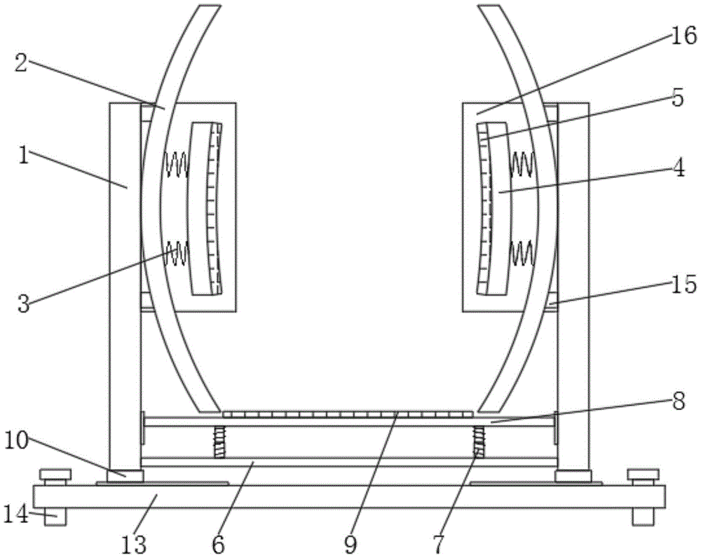
图1为一种转盘运输固定装置的整体结构示意图。FIG. 1 is a schematic diagram of the overall structure of a turntable transport fixing device.
图2为一种转盘运输固定装置中固定装置的结构示意图。FIG. 2 is a schematic structural diagram of a fixing device in a turntable transport fixing device.
图3为一种转盘运输固定装置的侧视结构示意图。FIG. 3 is a schematic side view of the structure of a turntable transport fixing device.
图4为一种转盘运输固定装置中安装板的俯视结构示意图。FIG. 4 is a schematic top view of the structure of a mounting plate in a transport fixing device for a turntable.
图中:1、固定板;2、弧形板;3、固定弹簧;4、挤压板;5、防滑垫;6、底板;7、弹簧伸缩杆;8、滑动板;9、软垫;10、移动块;11、固定装置;111、连接杆;112、竖板;113、移动板;114、挤压弹簧;115、卡接杆;12、滑动槽;13、安装板;14、安装螺丝;15、加强杆;16、隔板。In the figure: 1. Fixed plate; 2. Curved plate; 3. Fixed spring; 4. Extrusion plate; 5. Anti-skid pad; 6. Bottom plate; 7. Spring telescopic rod; 8. Sliding plate; 9. Soft pad; 10, moving block; 11, fixing device; 111, connecting rod; 112, vertical plate; 113, moving plate; 114, compression spring; 115, clamping rod; 12, sliding groove; 13, mounting plate; 14, installation Screws; 15. Reinforcing rods; 16. Partitions.
具体实施方式Detailed ways
下面将结合本实用新型实施例中的附图,对本实用新型实施例中的技术方案进行清楚、完整地描述,显然,所描述的实施例仅仅是本实用新型一部分实施例,而不是全部的实施例。基于本实用新型中的实施例,本领域普通技术人员在没有做出创造性劳动前提下所获得的所有其他实施例,都属于本实用新型保护的范围。The technical solutions in the embodiments of the present utility model will be clearly and completely described below with reference to the accompanying drawings in the embodiments of the present utility model. Obviously, the described embodiments are only a part of the embodiments of the present utility model, rather than all the implementations. example. Based on the embodiments of the present invention, all other embodiments obtained by those of ordinary skill in the art without creative work fall within the protection scope of the present invention.
请参阅图1~4,本实用新型实施例中,一种转盘运输固定装置,包括两个固定板1,两个固定板1相对的一侧均固定连接有弧形板2,两个弧形板2相对一侧的顶部和底部均固定连接有固定有固定弹簧3,四个固定弹簧3的另一端均固定连接有挤压板4,并且两个挤压板4相对的一侧均安装有防滑垫5,两个固定板1的背面均固定连接有隔板16,将转盘放置在两个挤压板4之间时,利用固定弹簧3自身的弹性力将转盘固定,防止转盘滚动,从而避免转盘损坏和脱离固定装置。Referring to FIGS. 1 to 4 , in the embodiment of the present invention, a turntable transportation fixing device includes two
两个固定板1的底部均固定连接有移动块10,两个移动块10的底部均设置有固定装置11,两个固定装置11的底部均通过滑动槽12滑动连接有安装板13,通过滑动槽12的设置,使得固定板1和弧形板2能够根据所固定的转盘规格而调整距离,使得本装置能够适应多种规格的转盘,从而增加本装置的普适性。The bottoms of the two
两个固定板1相对一侧之间的底部固定连接有底板6,底板6顶部的两侧均固定连接有弹簧伸缩杆7,两个弹簧伸缩杆7的顶端均固定连接有滑动板8,并且滑动板8的两侧分别与两个固定板1相对的一侧滑动连接,滑动板8的顶部安装有软垫9,当转盘抖动时,利用弹簧伸缩杆7自身的弹性力抵消转盘所受的冲击力,从而对转盘进行保护。The bottom between the opposite sides of the two
固定装置11包括连接杆111,连接杆111内壁的顶部和底部之间固定连接有竖板112,连接杆111内壁顶部和底部之间的两侧均滑动连接有移动板113,两个移动板113和竖板112相对的一侧之间均固定连接有挤压弹簧114,两个移动板113相对的一侧均固定连接有卡接杆115,卡接杆115表面会弧形,方便拉动,两个卡接杆115相离的一端均贯穿连接杆111并延伸至连接杆111的外部,两个卡接杆115延伸至连接杆111外部的一端均通过固定孔与滑动槽12卡接,固定孔的数量为多组,依次分布在滑动槽12内壁的两侧,通过固定装置11的设置,使得固定板1在移动到预定位置后可以固定在当前位置,保证转盘固定的稳定性。The fixing device 11 includes a connecting
安装板13顶部的两侧均贯穿有安装螺丝14,通过安装板13和安装螺14丝的设置,使得本装置方便固定在运输装置上,并且方便拆卸,使得运输装置在运输完转盘后可以运输其他的物品,增加运输装置的普适性。Both sides of the top of the
两个弧形板2相对一侧的顶部和底部均固定连接有加强杆15,并且四个加强杆15远离弧形板2的一端分别与两个固定板1相对的一侧固定连接。Reinforcing
本实用新型的工作原理是:The working principle of the utility model is:
拉动固定板1带动移动块10和固定装置11运动,固定板1移动到预定位置后利用挤压弹簧114自身的弹性力将卡接杆115弹出,使得卡接杆115与固定孔卡接,从而使得固定板1与安装板13连接,再将转盘放置在两个挤压板4之间时,利用固定弹簧3自身的弹性力将转盘固定,防止转盘滚动,并且当转盘抖动时,利用弹簧伸缩杆7自身的弹性力抵消转盘所受的冲击力,从而对转盘进行保护,并且在运输完成后,可以通过安装螺丝14将本装置拆卸,方便运输装置作为他用。Pull the fixing
以上所述,仅为本实用新型较佳的具体实施方式,但本实用新型的保护范围并不局限于此,任何熟悉本技术领域的技术人员在本实用新型揭露的技术范围内,根据本实用新型的技术方案及其实用新型构思加以等同替换或改变,都应涵盖在本实用新型的保护范围之内。The above description is only a preferred embodiment of the present invention, but the protection scope of the present invention is not limited to this. Equivalent replacement or modification of the new technical solution and its utility model concept shall be included within the protection scope of the present utility model.
Claims (6)
Priority Applications (1)
| Application Number | Priority Date | Filing Date | Title |
|---|---|---|---|
| CN201922369806.9U CN211365604U (en) | 2019-12-25 | 2019-12-25 | A turntable transport fixture |
Applications Claiming Priority (1)
| Application Number | Priority Date | Filing Date | Title |
|---|---|---|---|
| CN201922369806.9U CN211365604U (en) | 2019-12-25 | 2019-12-25 | A turntable transport fixture |
Publications (1)
| Publication Number | Publication Date |
|---|---|
| CN211365604U true CN211365604U (en) | 2020-08-28 |
Family
ID=72171452
Family Applications (1)
| Application Number | Title | Priority Date | Filing Date |
|---|---|---|---|
| CN201922369806.9U Expired - Fee Related CN211365604U (en) | 2019-12-25 | 2019-12-25 | A turntable transport fixture |
Country Status (1)
| Country | Link |
|---|---|
| CN (1) | CN211365604U (en) |
Cited By (3)
| Publication number | Priority date | Publication date | Assignee | Title |
|---|---|---|---|---|
| CN112620214A (en) * | 2020-11-30 | 2021-04-09 | 浙江省海洋水产研究所 | Large-scale marine benthos screening and washing device |
| CN113060398A (en) * | 2021-03-19 | 2021-07-02 | 深圳市爱租机科技有限公司 | Transport collision-prevention device for rental machine and working method thereof |
| WO2022052164A1 (en) * | 2020-09-08 | 2022-03-17 | 苏州元联科技创业园管理有限公司 | Transport tool for turbine |
-
2019
- 2019-12-25 CN CN201922369806.9U patent/CN211365604U/en not_active Expired - Fee Related
Cited By (4)
| Publication number | Priority date | Publication date | Assignee | Title |
|---|---|---|---|---|
| WO2022052164A1 (en) * | 2020-09-08 | 2022-03-17 | 苏州元联科技创业园管理有限公司 | Transport tool for turbine |
| CN112620214A (en) * | 2020-11-30 | 2021-04-09 | 浙江省海洋水产研究所 | Large-scale marine benthos screening and washing device |
| CN113060398A (en) * | 2021-03-19 | 2021-07-02 | 深圳市爱租机科技有限公司 | Transport collision-prevention device for rental machine and working method thereof |
| CN113060398B (en) * | 2021-03-19 | 2022-06-10 | 深圳市爱租机科技有限公司 | Transport collision-prevention device for rental machine and working method thereof |
Similar Documents
| Publication | Publication Date | Title |
|---|---|---|
| CN211853243U (en) | Positioning device for big data all-in-one machine | |
| CN104339195A (en) | Lightweight sheet workpiece machining fixture | |
| CN105128020A (en) | Clamping jaw with pre-positioning function | |
| CN210417387U (en) | Portable instrument based on commodity circulation is carried and is used | |
| CN210162112U (en) | Heat conduction structure rectifier diode conveyer | |
| CN205755199U (en) | Width-adjusting general instrument rack pallet | |
| CN206969984U (en) | A kind of removable damping suspender bracket | |
| CN216154506U (en) | A kind of handling equipment for aluminum production of hollow shutters | |
| CN205668804U (en) | A kind of clip claw mechanism | |
| CN212668045U (en) | A kind of stacking device for logistics | |
| CN105382772A (en) | Assembly table | |
| CN220501666U (en) | Buffering device of storage logistics goods shelf | |
| CN211642301U (en) | A transportation device used by social workers engaged in urban and rural community development | |
| CN212606914U (en) | Clean safe type aluminium book placement system | |
| CN210902078U (en) | Convenient and flexible combined desktop storage device for accounting office | |
| CN211321435U (en) | Vehicle-mounted router | |
| CN205928701U (en) | Lower hanging truss machine handle structure | |
| CN205333287U (en) | Adjustable testboard height fall machine | |
| CN211550928U (en) | Guide rail type base for air compressor | |
| CN218952883U (en) | Safety protection device for roof construction of steel structure building | |
| CN213566040U (en) | A measuring device for construction engineering management | |
| CN216464133U (en) | Automatic guide and balance pressing clamp | |
| CN213230467U (en) | Be used for absorbing workshop transportation equipment | |
| CN210920627U (en) | Positioning equipment mounting structure capable of being flexibly disassembled and assembled | |
| CN218791255U (en) | Goods shelves are used in internet commodity circulation of convenient letter sorting and transportation |
Legal Events
| Date | Code | Title | Description |
|---|---|---|---|
| GR01 | Patent grant | ||
| GR01 | Patent grant | ||
| CF01 | Termination of patent right due to non-payment of annual fee |
Granted publication date: 20200828 |
|
| CF01 | Termination of patent right due to non-payment of annual fee |