CN211362235U - Finished straight steel bar storage rack - Google Patents
Finished straight steel bar storage rack Download PDFInfo
- Publication number
- CN211362235U CN211362235U CN201922373935.5U CN201922373935U CN211362235U CN 211362235 U CN211362235 U CN 211362235U CN 201922373935 U CN201922373935 U CN 201922373935U CN 211362235 U CN211362235 U CN 211362235U
- Authority
- CN
- China
- Prior art keywords
- rods
- storage rack
- straight
- reinforcing bar
- vertical
- Prior art date
- Legal status (The legal status is an assumption and is not a legal conclusion. Google has not performed a legal analysis and makes no representation as to the accuracy of the status listed.)
- Expired - Fee Related
Links
- 238000003860 storage Methods 0.000 title claims abstract description 42
- 229910000831 Steel Inorganic materials 0.000 title description 19
- 239000010959 steel Substances 0.000 title description 19
- 230000003014 reinforcing effect Effects 0.000 claims abstract description 40
- 238000000151 deposition Methods 0.000 claims abstract description 6
- 230000001174 ascending effect Effects 0.000 claims abstract description 4
- 230000000694 effects Effects 0.000 abstract description 4
- 229910001294 Reinforcing steel Inorganic materials 0.000 description 24
- 239000003351 stiffener Substances 0.000 description 5
- 239000011150 reinforced concrete Substances 0.000 description 2
- 238000005096 rolling process Methods 0.000 description 2
- 238000009826 distribution Methods 0.000 description 1
- 238000000034 method Methods 0.000 description 1
- 238000007789 sealing Methods 0.000 description 1
- XLYOFNOQVPJJNP-UHFFFAOYSA-N water Substances O XLYOFNOQVPJJNP-UHFFFAOYSA-N 0.000 description 1
Images


Landscapes
- Warehouses Or Storage Devices (AREA)
Abstract
The utility model relates to a straight reinforcing bar storage rack of finished product belongs to reinforcing bar strorage device's technical field, and it includes the support frame, the support frame includes a pair of parallel arrangement's vertical pole, be provided with vertical ascending dead lever on the vertical pole respectively, the both sides of dead lever all are provided with the bracing piece that is used for depositing straight reinforcing bar, the both ends fixedly connected with of bracing piece is used for restricting the locating part that straight reinforcing bar breaks away from along vertical direction. The utility model discloses have the effect of depositing safety and stability.
Description
Technical Field
The utility model belongs to the technical field of the technique of reinforcing bar strorage device and specifically relates to a straight reinforcing bar storage rack of finished product is related to.
Background
The reinforcing steel bar is steel for reinforced concrete and prestressed reinforced concrete, and the cross section of the reinforcing steel bar is circular or square with round corners. Comprises plain round steel bars, ribbed steel bars and twisted steel bars.
The invention discloses a straight steel bar storage and transportation frame which comprises an underframe structure and a vertical support frame arranged on the underframe structure, wherein a plurality of groups of support arms are arranged on the front surface and the back surface of the vertical support frame in parallel from top to bottom, and the support arms are arranged in an upward inclined manner. When the reinforcing steel bar is stored, the reinforcing steel bar is placed on the support arm which is inclined upwards, and the limiting mechanism is not arranged above the support arm, so that the reinforcing steel bar can fall off from the upper part of the support arm, and potential safety hazards are caused.
SUMMERY OF THE UTILITY MODEL
Not enough to prior art exists, the utility model aims at providing a straight reinforcing bar storage rack of finished product, it has the effect of depositing safety and stability.
The above utility model discloses an above-mentioned utility model purpose can realize through following technical scheme: the utility model provides a straight reinforcing bar storage rack of finished product, includes the support frame, the support frame includes a pair of parallel arrangement's vertical pole, be provided with vertical ascending dead lever on the vertical pole respectively, the both sides of dead lever all are provided with the bracing piece that is used for depositing straight reinforcing bar, the both ends fixedly connected with of bracing piece is used for restricting the locating part that straight reinforcing bar breaks away from along vertical direction.
By adopting the technical scheme, when the straight reinforcing steel bar is stored, the straight reinforcing steel bar penetrates through the gap between the limiting piece and the supporting rod, and when the two ends of the straight reinforcing steel bar are lapped on the supporting rods at the two ends, the limiting piece can limit the vertical direction of the straight reinforcing steel bar, so that the straight reinforcing steel bar can be prevented from being separated from the vertical direction; when the straight steel bar needs to be taken down, the straight steel bar is pulled out from the outer sides of the supporting rod and the limiting piece.
The present invention may be further configured in a preferred embodiment as: the two ends of the supporting rod are provided with limiting parts which protrude out of the supporting rod and are provided with inclined planes.
Through adopting above-mentioned technical scheme, can prevent that straight reinforcing bar from taking place to roll along the bracing piece to can reduce straight reinforcing bar and take place the possibility that drops along the bracing piece.
The present invention may be further configured in a preferred embodiment as: the inner side of the upper surface of the support rod, which is positioned at the limiting part, is provided with a wavy fixed groove.
Through adopting above-mentioned technical scheme, when will straightening the reinforcing bar and place on the bracing piece, can will straighten the reinforcing bar card in the fixed slot through setting up the fixed slot, further promote the security performance when the brace rod is deposited.
The present invention may be further configured in a preferred embodiment as: the limiting part comprises a pair of vertical rods arranged on the upper surface of the limiting part in the vertical upward direction, and the top ends of the vertical rods are fixedly connected with limiting rods.
Through adopting above-mentioned technical scheme, can make the periphery of straight reinforcing bar form confined annular to can avoid straight reinforcing bar to take place to break away from by vertical direction.
The present invention may be further configured in a preferred embodiment as: an upper layer of storage part and a lower layer of storage part are arranged on the fixed rod.
Through adopting above-mentioned technical scheme for be provided with upper and lower two-layer storage component on the support frame, can improve the utilization ratio in space, increase the storage capacity of straight reinforcing bar on the storage rack.
The present invention may be further configured in a preferred embodiment as: a cross rod is connected between the pair of fixing rods, and a plurality of storage parts are arranged on two sides of the cross rod in a staggered mode.
Through adopting above-mentioned technical scheme, the crisscross storage device that is provided with in both sides of the regional horizontal pole that lies in between two bracing pieces on the horizontal pole can play the effect of support to the alignment reinforcing bar to the storage device that can avoid both ends bears the pressure too big and takes place the fracture.
The present invention may be further configured in a preferred embodiment as: a pair of reinforcing rods is fixedly connected between the supporting rods and the longitudinal rods, which are vertically arranged on the fixing rods, and isosceles triangles are arranged between the reinforcing rods and the supporting rods or the longitudinal rods, which are positioned on the lower sides of the two reinforcing rods.
Through adopting above-mentioned technical scheme for form the triangle-shaped structure between the bracing piece that is located the outside and the vertical pole, thereby strengthen support frame structure's intensity, improved the factor of safety of storage rack.
The present invention may be further configured in a preferred embodiment as: and self-locking trundles are arranged on the lower bottom surfaces of the longitudinal rods.
Through adopting above-mentioned technical scheme, when needs transported the straight reinforcing bar, through placing straight reinforcing bar on the storage rack, then promote the storage rack and can realize transporting the straight reinforcing bar.
To sum up, the utility model discloses a following at least one useful technological effect:
1. when the straight reinforcing steel bar is stored, the straight reinforcing steel bar penetrates through a gap between the limiting piece and the supporting rod, and when two ends of the straight reinforcing steel bar are lapped on the supporting rods at two ends, the limiting piece can limit the vertical direction of the straight reinforcing steel bar, so that the straight reinforcing steel bar can be prevented from being separated from the vertical direction; when the straight steel bar needs to be taken down, the straight steel bar is drawn out from the outer sides of the supporting rod and the limiting piece;
2. the limiting parts which protrude out of the supporting rods and are provided with the inclined planes are arranged at the two ends of the supporting rods, so that the straight reinforcing steel bars can be prevented from rolling along the supporting rods, and the possibility of falling off of the straight reinforcing steel bars along the supporting rods can be reduced;
3. the wavy fixed groove is formed in the inner side, located at the limiting portion, of the upper surface of the supporting rod, so that the straight steel bars can be clamped in the fixed groove, and the safety performance of the supporting bars during storage is further improved.
Drawings
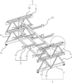
Fig. 1 is a schematic structural view of the whole of the present embodiment.
Fig. 2 is a partially enlarged schematic view of a portion a in fig. 1.
Fig. 3 is a schematic structural view of the storage member in the present embodiment.
In the figure, 1, a support frame; 11. a longitudinal bar; 12. a cross bar; 13. fixing the rod; 2. a storage member; 21. a support bar; 22. fixing grooves; 23. a limiting part; 3. a limiting member; 31. a vertical rod; 32. a limiting rod; 4. a reinforcing bar; 5. self-locking caster wheels.
Detailed Description
The present invention will be described in further detail with reference to the accompanying drawings.
As shown in fig. 1, for the utility model discloses a straight reinforcing bar storage rack of finished product, including support frame 1, support frame 1 includes parallel distribution's vertical pole 11 in a pair of horizontal direction, connects through a horizontal pole 12 in the middle of two vertical poles 11 are positive, and the positive intermediate position of two vertical poles 11 upper surfaces is provided with vertical ascending dead lever 13, and the centre and the top of two dead levers 13 still are provided with two horizontal poles 12 and are connected with the dead lever 13 of both sides, and three horizontal poles 12 are equidistant setting from top to bottom. A pair of storage parts 2 are respectively arranged on two sides of the two cross rods 12 on the upper side of each fixing rod 13, and a limiting part 3 is respectively arranged on each storage part 2 to limit the vertical direction of the straight reinforcing steel bars, so that the straight reinforcing steel bars cannot be separated from the storage parts 2. The storage amount of the storage rack for aligning the steel bars can be increased by arranging the storage parts 2 on two sides of the upper cross rod 12 and the lower cross rod 12.
As shown in fig. 1 and 3, the storage part 2 includes support rods 21 disposed on two sides of the fixing rod 13, a wave-shaped fixing groove 22 for clamping the straight steel bar is disposed on the upper surface of the support rod 21, two sides of the fixing groove 22 on the support rod 21 are provided with limiting portions 23 with inclined planes, when the straight steel bar is placed on the support rod 21, the straight steel bar can be clamped in the fixing groove 22, and the limiting portions 23 with inclined planes are disposed to prevent the straight steel bar from rolling along the support rod 21 and sliding down from the end of the support rod 21.
As shown in fig. 1 and 2, the limiting member 3 includes a pair of vertical rods 31 disposed on the upper surface of the limiting portion 23 of the supporting rod 21, and the top ends of the two vertical rods 31 limit the vertical movement of the straight reinforcing steel bar through the limiting rod 32, so as to prevent the straight reinforcing steel bar from falling off from the top of the supporting rod 21. When the straight reinforcing steel bars are taken down from the storage rack, the straight reinforcing steel bars are drawn out from two sides of the supporting rod 21.
The storage parts 2 are arranged on two sides of the two transverse rods 12 on the upper side in a staggered mode, and the fixing grooves 22 on the supporting rods 21 on the same side on the transverse rods 12 are all aligned, so that straight reinforcing steel bars can be stored on the supporting rods 21 more stably.
Because the quality of straight reinforcing bar is great, so use the back bracing piece 21 that may be broken after long, in order to strengthen the support intensity of bracing piece 21, two bracing pieces 21 about the outside and be located are provided with a pair of stiffener 4 between bracing piece 21 and the horizontal pole 12 of downside respectively, stiffener 4 sets up on the side of bracing piece 21 the outside, every 4 upside of stiffener sets up adjacently, the downside sets up apart from each other, thereby can make two stiffeners 4 and bracing piece 21 of downside or be the triangle-shaped setting between two stiffeners 4 and the horizontal pole 12, and then strengthen the intensity of storage rack.
At the both ends fixedly connected with auto-lock truckle 5 of horizontal pole 12 lower surface, can conveniently transport the alignment reinforcing bar through setting up auto-lock truckle 5, saved a large amount of manpowers.
The implementation principle of the embodiment is as follows: when depositing the alignment reinforcing bar, will straighten the one end of reinforcing bar and penetrate and the joint in same water flat line's fixed slot 22 by the gag lever post 32 downside, when the both ends difference joint of straight reinforcing bar is on the bracing piece 21 of outermost both sides, can realize leaving the straight reinforcing bar in on the bracing piece 21, can prevent moreover that the top of straight reinforcing bar by bracing piece 21 from taking place to break away from, improved the stability that straight reinforcing bar was deposited. When the straight steel bar needs to be taken down, the straight steel bar is drawn out from the space between the sealing rod and the support rod 21.
The embodiment of this specific implementation mode is the preferred embodiment of the present invention, not limit according to this the utility model discloses a protection scope, so: all equivalent changes made according to the structure, shape and principle of the utility model are covered within the protection scope of the utility model.
Claims (8)
1. The utility model provides a straight reinforcing bar storage rack of finished product, includes support frame (1), support frame (1) includes a pair of parallel arrangement's vertical pole (11), be provided with vertical ascending dead lever (13) on vertical pole (11) respectively, the both sides of dead lever (13) all are provided with bracing piece (21) that are used for depositing straight reinforcing bar, its characterized in that: both ends fixedly connected with of bracing piece (21) is used for restricting straight reinforcing bar along locating part (3) that vertical direction breaks away from.
2. The finished straight rebar storage rack of claim 1, wherein: and two ends of the supporting rod (21) are provided with limiting parts (23) which protrude out of the supporting rod (21) and are provided with inclined planes.
3. The finished straight rebar storage rack of claim 2, wherein: the inner side of the upper surface of the support rod (21) positioned at the limiting part (23) is provided with a wave-shaped fixing groove (22).
4. The finished straight rebar storage rack of claim 2, wherein: the limiting part (3) comprises a pair of vertical rods (31) arranged on the upper surface of the limiting part (23) vertically upwards, and the top ends of the vertical rods (31) are fixedly connected with limiting rods (32).
5. The finished straight rebar storage rack of claim 1, wherein: an upper layer and a lower layer of storage parts (2) are arranged on the fixed rod (13).
6. The finished straight rebar storage rack of claim 1, wherein: a cross rod (12) is connected between the pair of fixing rods (13), and a plurality of storage parts (2) are arranged on two sides of the cross rod (12) in a staggered mode.
7. The finished straight rebar storage rack of claim 1, wherein: a pair of reinforcing rods (4) are fixedly connected between the supporting rods (21) and the longitudinal rods (11), which are vertically arranged on the fixing rod (13), and the reinforcing rods (4) and the supporting rods (21) or the longitudinal rods (11) which are positioned on the lower sides of the two reinforcing rods (4) are arranged in an isosceles triangle manner.
8. The finished straight rebar storage rack of claim 1, wherein: and self-locking trundles (5) are arranged on the lower bottom surfaces of the longitudinal rods (11).
Priority Applications (1)
| Application Number | Priority Date | Filing Date | Title |
|---|---|---|---|
| CN201922373935.5U CN211362235U (en) | 2019-12-25 | 2019-12-25 | Finished straight steel bar storage rack |
Applications Claiming Priority (1)
| Application Number | Priority Date | Filing Date | Title |
|---|---|---|---|
| CN201922373935.5U CN211362235U (en) | 2019-12-25 | 2019-12-25 | Finished straight steel bar storage rack |
Publications (1)
| Publication Number | Publication Date |
|---|---|
| CN211362235U true CN211362235U (en) | 2020-08-28 |
Family
ID=72167319
Family Applications (1)
| Application Number | Title | Priority Date | Filing Date |
|---|---|---|---|
| CN201922373935.5U Expired - Fee Related CN211362235U (en) | 2019-12-25 | 2019-12-25 | Finished straight steel bar storage rack |
Country Status (1)
| Country | Link |
|---|---|
| CN (1) | CN211362235U (en) |
Cited By (1)
| Publication number | Priority date | Publication date | Assignee | Title |
|---|---|---|---|---|
| CN116021493A (en) * | 2023-02-09 | 2023-04-28 | 奇瑞汽车股份有限公司 | Automotive chassis front module assembly |
-
2019
- 2019-12-25 CN CN201922373935.5U patent/CN211362235U/en not_active Expired - Fee Related
Cited By (1)
| Publication number | Priority date | Publication date | Assignee | Title |
|---|---|---|---|---|
| CN116021493A (en) * | 2023-02-09 | 2023-04-28 | 奇瑞汽车股份有限公司 | Automotive chassis front module assembly |
Similar Documents
| Publication | Publication Date | Title |
|---|---|---|
| CN206722221U (en) | Square type frame column horizontal truss stirrup anti-seismic steel bar cage | |
| CN209553039U (en) | Self-traveling module transport vehicle transport lift beam | |
| CN103088950A (en) | Floor plate steel truss structure | |
| CN109515977A (en) | Piling bin and its manufacture craft and stacking method for prefabricated components | |
| CN208344908U (en) | Adjustable pallet for fabricated shear wall | |
| CN203544077U (en) | Loading trolley | |
| CN103485485B (en) | Concrete column with enhanced oblique strength through distributed reinforcing steel bars in local corner areas and manufacturing method of concrete column | |
| CN202731316U (en) | Operating platform capable of protecting reinforcing mesh from being treaded | |
| CN211765803U (en) | Double-block type sleeper steel bar truss's floor truck | |
| CN203022166U (en) | Concrete shear wall provided with continuous annular steel reinforcement structures | |
| CN211368420U (en) | Main tower lower beam diagonal bracing system | |
| CN206015700U (en) | A kind of raft foundation steelframe support | |
| CN211392599U (en) | Three-dimensional horizontal storage goods shelves of electrical steel reel for iron core | |
| CN205600693U (en) | Frame is put to portable stirrup | |
| CN210365423U (en) | Trestle support with light steel structure | |
| CN209522051U (en) | Piling bin for prefabricated components | |
| CN211448714U (en) | Shield constructs section of jurisdiction and stacks base | |
| CN210365078U (en) | Precast beam transportation damping device | |
| CN203878739U (en) | Lightweight steel structure building system | |
| CN223385134U (en) | Steel bar finished product transportation frame | |
| CN206800805U (en) | A kind of Steel bar rack for super thick raft plate | |
| CN222924019U (en) | From split heads muscle of taking protective layer | |
| CN207902927U (en) | A kind of bracing means for pile packing case | |
| CN215802688U (en) | Regularization wheeled reinforcing bar split heads | |
| CN220353161U (en) | Corrugated steel plate composite shear wall with frames in staggered arrangement |
Legal Events
| Date | Code | Title | Description |
|---|---|---|---|
| GR01 | Patent grant | ||
| GR01 | Patent grant | ||
| CF01 | Termination of patent right due to non-payment of annual fee | ||
| CF01 | Termination of patent right due to non-payment of annual fee |
Granted publication date: 20200828 |