CN211316956U - A ceramic sintering device with insulating function - Google Patents
A ceramic sintering device with insulating function Download PDFInfo
- Publication number
- CN211316956U CN211316956U CN201921883243.9U CN201921883243U CN211316956U CN 211316956 U CN211316956 U CN 211316956U CN 201921883243 U CN201921883243 U CN 201921883243U CN 211316956 U CN211316956 U CN 211316956U
- Authority
- CN
- China
- Prior art keywords
- ceramic sintering
- isolation box
- plate
- box
- pipeline
- Prior art date
- Legal status (The legal status is an assumption and is not a legal conclusion. Google has not performed a legal analysis and makes no representation as to the accuracy of the status listed.)
- Active
Links
Images


Landscapes
- Furnace Details (AREA)
Abstract
本实用新型公开了一种具有隔绝功能的陶瓷烧结装置,包括隔离箱和连接管道,所述隔离箱的前侧转动连接有箱门,且隔离箱内滑动连接有承载板,所述隔离箱的内顶部固定有液压缸,且液压缸的下侧通过液压杆与吊板相连接,所述吊板的下端面固定有连接杆,且连接杆之间设置有输送管道,同时输送管道的内侧设置有燃气喷头,所述连接管道设置在输送管道的上侧,且连接管道贯穿吊板,所述连接管道的上侧通过管箍与进气管道相连接,且进气管道贯穿隔离箱的顶部。该具有隔绝功能的陶瓷烧结装置,将陶瓷对应放置在置物板上后,手动向后推动承载板,直至承载板完全处在隔离箱内,接着向后转动箱门,此时隔离箱处在封闭状态,从而起到隔热的作用。
The utility model discloses a ceramic sintering device with isolation function, which comprises an isolation box and a connecting pipeline. A box door is rotatably connected to the front side of the isolation box, and a bearing plate is slidably connected in the isolation box. A hydraulic cylinder is fixed on the inner top, and the lower side of the hydraulic cylinder is connected with a hanging plate through a hydraulic rod, a connecting rod is fixed on the lower end surface of the hanging plate, and a conveying pipe is arranged between the connecting rods, and the inner side of the conveying pipe is arranged at the same time. There is a gas nozzle, the connecting pipe is arranged on the upper side of the conveying pipe, and the connecting pipe runs through the hanger plate. In the ceramic sintering device with isolation function, after placing the ceramics on the storage board, manually push the carrying board backward until the carrying board is completely in the isolation box, and then rotate the box door backward, and the isolation box is closed at this time. state, so as to play the role of heat insulation.
Description
技术领域technical field
本实用新型具体涉及陶瓷烧结相关技术领域,具体为一种具有隔绝功能的陶瓷烧结装置。The utility model particularly relates to the technical field of ceramic sintering, in particular to a ceramic sintering device with an insulating function.
背景技术Background technique
用陶土烧制的器皿叫陶器,用瓷土烧制的器皿叫瓷器,陶瓷则是陶器、炻器和瓷器的总称,烧结,是指把粉状物料转变为致密体,是一个传统的工艺过程,人们很早就利用这个工艺来生产陶瓷、粉末冶金、耐火材料、超高温材料等,在对陶瓷原料进行烧结的过程中需要使用到陶瓷烧结装置。The utensils fired with clay are called pottery, the utensils fired with china clay are called porcelain, and ceramics are the general term for pottery, stoneware and porcelain. Sintering refers to the transformation of powdery materials into dense bodies, which is a traditional process. People have used this process for a long time to produce ceramics, powder metallurgy, refractory materials, ultra-high temperature materials, etc., and a ceramic sintering device is required in the process of sintering ceramic raw materials.
现有的陶瓷烧结装置在对陶瓷烧结的过程中,陶瓷直接暴露在外界易出现热量大量散失的现象,且陶瓷得不到均匀全面的高温加热处理,从而影响烧结质量,因此使用起来不够便捷,针对上述问题,需要对现有的设备进行改进。During the sintering process of the existing ceramic sintering device, the ceramic is directly exposed to the outside, and a large amount of heat is easily lost, and the ceramic cannot be heated uniformly and comprehensively at a high temperature, thereby affecting the sintering quality, so it is not convenient to use. In view of the above problems, the existing equipment needs to be improved.
实用新型内容Utility model content
本实用新型的目的在于提供一种具有隔绝功能的陶瓷烧结装置,以解决上述背景技术中提出的现有的陶瓷烧结装置在对陶瓷烧结的过程中,陶瓷直接暴露在外界易出现热量大量散失的现象,且陶瓷得不到均匀全面的高温加热处理,从而影响烧结质量的问题。The purpose of the present invention is to provide a ceramic sintering device with an insulating function, so as to solve the problem that the existing ceramic sintering device proposed in the above-mentioned background technology is prone to a large amount of heat loss when the ceramic is directly exposed to the outside during the process of sintering the ceramic. phenomenon, and the ceramics cannot be uniformly and comprehensively treated at high temperature, thus affecting the sintering quality.
为实现上述目的,本实用新型提供如下技术方案:一种具有隔绝功能的陶瓷烧结装置,包括隔离箱和连接管道,所述隔离箱的前侧转动连接有箱门,且隔离箱内滑动连接有承载板,同时承载板上转动连接有置物板,所述隔离箱的内顶部固定有液压缸,且液压缸的下侧通过液压杆与吊板相连接,所述吊板的下端面固定有连接杆,且连接杆之间设置有输送管道,同时输送管道的内侧设置有燃气喷头,所述连接管道设置在输送管道的上侧,且连接管道贯穿吊板,所述连接管道的上侧通过管箍与进气管道相连接,且进气管道贯穿隔离箱的顶部。In order to achieve the above purpose, the present utility model provides the following technical solutions: a ceramic sintering device with isolation function, comprising an isolation box and a connecting pipe, the front side of the isolation box is rotatably connected with a box door, and the isolation box is slidably connected with a A carrying plate, at the same time, a storage plate is rotatably connected to the carrying plate, a hydraulic cylinder is fixed on the inner top of the isolation box, and the lower side of the hydraulic cylinder is connected with a hanging plate through a hydraulic rod, and the lower end face of the hanging plate is fixed with a connection rods, and between the connecting rods there is a conveying pipe, and the inside of the conveying pipe is provided with a gas nozzle, the connecting pipe is arranged on the upper side of the conveying pipe, and the connecting pipe runs through the hanger plate, and the upper side of the connecting pipe The hoop is connected with the air inlet pipe, and the air inlet pipe runs through the top of the isolation box.
优选的,所述隔离箱的左右内壁上均固定有滑轨,且滑轨之间滑动连接有承载板。Preferably, slide rails are fixed on the left and right inner walls of the isolation box, and a bearing plate is slidably connected between the slide rails.
优选的,所述承载板的下侧固定有电机,且电机的上侧通过电机轴转动连接有置物板。Preferably, a motor is fixed on the lower side of the carrying plate, and an object storage board is rotatably connected to the upper side of the motor through the motor shaft.
优选的,所述液压缸通过液压杆与吊板之间构成伸缩结构,且吊板通过螺栓螺纹连接在液压杆上。Preferably, the hydraulic cylinder forms a telescopic structure between the hydraulic rod and the hanger plate, and the hanger plate is threadedly connected to the hydraulic rod through bolts.
优选的,所述输送管道的竖直中轴线与置物板的竖直中轴线重合,且置物板和输送管道均设置有两个。Preferably, the vertical central axis of the conveying pipe coincides with the vertical central axis of the storage board, and there are two storage boards and two conveying pipes.
优选的,所述燃气喷头均匀分布在输送管道上。Preferably, the gas nozzles are evenly distributed on the conveying pipeline.
与现有技术相比,本实用新型的有益效果是:该具有隔绝功能的陶瓷烧结装置,Compared with the prior art, the beneficial effect of the present utility model is: the ceramic sintering device with insulating function,
(1)将陶瓷对应放置在置物板上后,手动向后推动承载板,直至承载板完全处在隔离箱内,接着向后转动箱门,此时隔离箱处在封闭状态,从而起到隔热的作用,防止陶瓷在烧结的过程中出现热量散失的现象,烧结完成后,向前转动箱门,再向前拉动承载板,以便取出陶瓷;(1) After placing the ceramic correspondingly on the storage board, manually push the carrying board backward until the carrying board is completely in the isolation box, and then turn the box door backward. The effect of heat prevents the heat loss of the ceramics during the sintering process. After the sintering is completed, turn the box door forward, and then pull the carrier plate forward to take out the ceramics;
(2)吊板可在液压缸和液压杆的作用下向下移动,从而带动输送管道向下移动,直至输送管道包裹在陶瓷的外侧,从而对陶瓷进行全面烧结,以此加快烧结速度,烧结完成后,输送管道向上移动,直至输送管道完全处在陶瓷的上方,从而方便后续陶瓷的拿取工作;(2) The hanging plate can move downward under the action of the hydraulic cylinder and the hydraulic rod, thereby driving the conveying pipeline to move downward until the conveying pipeline is wrapped on the outside of the ceramic, so as to sinter the ceramic in an all-round way, thereby speeding up the sintering speed and sintering. After completion, the conveying pipe moves upward until the conveying pipe is completely above the ceramics, so as to facilitate the subsequent work of taking the ceramics;
(3)陶瓷在烧结的过程中,置物板可在电机和电机轴的作用下转动,从而带动陶瓷转动,使陶瓷得到更加全面均匀的高温加热处理。(3) During the sintering process of ceramics, the storage plate can be rotated under the action of the motor and the motor shaft, thereby driving the ceramics to rotate, so that the ceramics can be heated more comprehensively and uniformly at high temperature.
附图说明Description of drawings
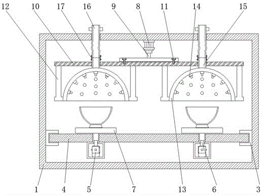
图1为本实用新型正视剖面结构示意图;Fig. 1 is the front view sectional structure schematic diagram of the utility model;
图2为本实用新型正视外观结构示意图;Fig. 2 is the front view structure schematic diagram of the utility model;
图3为本实用新型俯视剖面结构示意图。FIG. 3 is a schematic top view sectional structure diagram of the utility model.
图中:1、隔离箱,2、箱门,3、滑轨,4、承载板,5、电机,6、电机轴,7、置物板,8、液压缸,9、液压杆,10、吊板,11、螺栓,12、连接杆,13、输送管道,14、燃气喷头,15、连接管道,16、进气管道,17、管箍。In the picture: 1. Isolation box, 2. Box door, 3. Slide rail, 4. Loading plate, 5. Motor, 6. Motor shaft, 7. Storage board, 8. Hydraulic cylinder, 9. Hydraulic rod, 10. Hanging Plate, 11, Bolts, 12, Connecting Rod, 13, Conveying Pipe, 14, Gas Nozzle, 15, Connecting Pipe, 16, Inlet Pipe, 17, Pipe Hoop.
具体实施方式Detailed ways
下面将结合本实用新型实施例中的附图,对本实用新型实施例中的技术方案进行清楚、完整地描述,显然,所描述的实施例仅仅是本实用新型一部分实施例,而不是全部的实施例。基于本实用新型中的实施例,本领域普通技术人员在没有做出创造性劳动前提下所获得的所有其他实施例,都属于本实用新型保护的范围。The technical solutions in the embodiments of the present utility model will be clearly and completely described below with reference to the accompanying drawings in the embodiments of the present utility model. Obviously, the described embodiments are only a part of the embodiments of the present utility model, rather than all the implementations. example. Based on the embodiments of the present invention, all other embodiments obtained by those of ordinary skill in the art without creative work fall within the protection scope of the present invention.
请参阅图1-3,本实用新型提供一种技术方案:一种具有隔绝功能的陶瓷烧结装置,根据图1所示,隔离箱1的前侧转动连接有箱门2,且隔离箱1内滑动连接有承载板4,同时承载板4上转动连接有置物板7,隔离箱1的左右内壁上均固定有滑轨3,且滑轨3之间滑动连接有承载板4,承载板4可在滑轨3之间前后滑动,从而方便陶瓷的放置和拿取,承载板4的下侧固定有电机5,且电机5的上侧通过电机轴6转动连接有置物板7,置物板7可在电机5和电机轴6的作用下转动,从而带动陶瓷转动,使陶瓷得到更加全面均匀的加热处理,以此提高烧结质量。1-3, the present utility model provides a technical solution: a ceramic sintering device with an insulating function. As shown in FIG. A
根据图1和图2所示,隔离箱1的内顶部固定有液压缸8,且液压缸8的下侧通过液压杆9与吊板10相连接,液压缸8通过液压杆9与吊板10之间构成伸缩结构,且吊板10通过螺栓11螺纹连接在液压杆9上,吊板10可在液压缸8和液压杆9的作用下上下移动,吊板10在向下移动的过程中可带动输送管道13向下移动,直至输送管道13包裹在陶瓷的外侧,使燃气喷头14贴近陶瓷加热,减少热量的散失,以此加快烧结速度。As shown in FIGS. 1 and 2 , a
根据图1、图2和图3所示,吊板10的下端面固定有连接杆12,且连接杆12之间设置有输送管道13,同时输送管道13的内侧设置有燃气喷头14,输送管道13的竖直中轴线与置物板7的竖直中轴线重合,且置物板7和输送管道13均设置有两个,两个置物板7上均可放置陶瓷,且输送管道13中的燃气可通过燃气喷头14排出,以此对应的陶瓷进行高温加热处理,燃气喷头14均匀分布在输送管道13上,均匀分布的燃气喷头14可使陶瓷得到更加均匀的加热处理,连接管道15设置在输送管道13的上侧,且连接管道15贯穿吊板10,连接管道15的上侧通过管箍17与进气管道16相连接,且进气管道16贯穿隔离箱1的顶部。As shown in FIGS. 1 , 2 and 3 , connecting
工作原理:在使用该具有隔绝功能的陶瓷烧结装置时,接通至外电源,首先向前拉动承载板4并将陶瓷放置在对应的置物板7上,再向后推动承载板4,此时承载板4的左右两侧在滑轨3上滑动,直至承载板4完全处在隔离箱1内,再向后转动箱门2,使隔离箱1内部处在封闭状态下,启动液压缸8,液压缸8带动液压杆9伸长,从而带动吊板10向下移动,输送管道13随之向下移动,直至输送管道13包裹在陶瓷的外侧,随后向进气管道16内通入燃气,燃气通过连接管道15进入到输送管道13内,燃气喷头14点燃输送管道13内的燃气并均匀对陶瓷进行高温加热,同时启动电机5,电机5带动电机轴6转动,从而带动置物板7转动,陶瓷随之转动,从而使陶瓷得到更加全面均匀的高温加热处理,烧结完成后,输送管道13向上移动,再向前转动箱门2并向前拉动承载板4,以此取出陶瓷,工作结束后,取下螺栓11和管箍17可将吊板10拆卸下来,方便对其上的零件进行维修,这就完成整个工作,且本说明书中未作详细描述的内容属于本领域专业技术人员公知的现有技术。Working principle: When using the ceramic sintering device with isolation function, connect to the external power supply, first pull the
术语“中心”、“纵向”、“横向”、“前”、“后”、“左”、“右”、“竖直”、“水平”、“顶”、“底”、“内”、“外”等指示的方位或位置关系为基于附图所示的方位或位置关系,仅是为便于描述本实用新型的简化描述,而不是指示或暗指所指的装置或元件必须具有特定的方位、为特定的方位构造和操作,因而不能理解为对本实用新型保护内容的限制。The terms "center", "portrait", "horizontal", "front", "rear", "left", "right", "vertical", "horizontal", "top", "bottom", "inner", The orientation or positional relationship indicated by "outside" is based on the orientation or positional relationship shown in the accompanying drawings, and is only a simplified description for the convenience of describing the present invention, rather than indicating or implying that the indicated device or element must have a specific Orientation, construction and operation are specific orientations, and therefore should not be construed as limiting the protection content of the present invention.
尽管参照前述实施例对本实用新型进行了详细的说明,对于本领域的技术人员来说,其依然可以对前述各实施例所记载的技术方案进行修改,或者对其中部分技术特征进行等同替换,凡在本实用新型的精神和原则之内,所作的任何修改、等同替换、改进等,均应包含在本实用新型的保护范围之内。Although the present invention has been described in detail with reference to the foregoing embodiments, for those skilled in the art, it is still possible to modify the technical solutions described in the foregoing embodiments, or perform equivalent replacements for some of the technical features. Within the spirit and principle of the present utility model, any modifications, equivalent replacements, improvements, etc. made shall be included within the protection scope of the present utility model.
Claims (6)
Priority Applications (1)
| Application Number | Priority Date | Filing Date | Title |
|---|---|---|---|
| CN201921883243.9U CN211316956U (en) | 2019-11-04 | 2019-11-04 | A ceramic sintering device with insulating function |
Applications Claiming Priority (1)
| Application Number | Priority Date | Filing Date | Title |
|---|---|---|---|
| CN201921883243.9U CN211316956U (en) | 2019-11-04 | 2019-11-04 | A ceramic sintering device with insulating function |
Publications (1)
| Publication Number | Publication Date |
|---|---|
| CN211316956U true CN211316956U (en) | 2020-08-21 |
Family
ID=72053148
Family Applications (1)
| Application Number | Title | Priority Date | Filing Date |
|---|---|---|---|
| CN201921883243.9U Active CN211316956U (en) | 2019-11-04 | 2019-11-04 | A ceramic sintering device with insulating function |
Country Status (1)
| Country | Link |
|---|---|
| CN (1) | CN211316956U (en) |
Cited By (2)
| Publication number | Priority date | Publication date | Assignee | Title |
|---|---|---|---|---|
| CN112713220A (en) * | 2020-12-31 | 2021-04-27 | 阳光中科(福建)能源股份有限公司 | Perc solar cell organic component sintering device |
| CN115540601A (en) * | 2022-09-08 | 2022-12-30 | 湖南省新化县鑫星电子陶瓷有限责任公司 | A ceramic sintering device with protective structure |
-
2019
- 2019-11-04 CN CN201921883243.9U patent/CN211316956U/en active Active
Cited By (2)
| Publication number | Priority date | Publication date | Assignee | Title |
|---|---|---|---|---|
| CN112713220A (en) * | 2020-12-31 | 2021-04-27 | 阳光中科(福建)能源股份有限公司 | Perc solar cell organic component sintering device |
| CN115540601A (en) * | 2022-09-08 | 2022-12-30 | 湖南省新化县鑫星电子陶瓷有限责任公司 | A ceramic sintering device with protective structure |
Similar Documents
| Publication | Publication Date | Title |
|---|---|---|
| CN209470431U (en) | A kind of wide-mouth ceramic flash drying machine | |
| CN108397996A (en) | A kind of good drying equipment of using effect for new material processing | |
| CN108582444A (en) | One kind having intelligentized control method building brick manufacture production equipment | |
| CN105272119A (en) | Uniform compaction method of silicon oxide based antenna housing composite | |
| CN210242402U (en) | High-efficient sintering device of alumina ceramics | |
| CN116294512A (en) | A drying room structure using waste heat for drying | |
| CN210741089U (en) | Kiln equipment for ceramic manufacture | |
| CN211679883U (en) | Mould shell roasting furnace for investment casting | |
| CN209820151U (en) | Electrolysis rotation type sintering device for preparing nano catalytic material | |
| CN107696259A (en) | A kind of material of brick production processing unit (plant) | |
| CN205066422U (en) | Multipurpose microwave high temperature roller kilns | |
| CN209431777U (en) | A kind of shaping and drying device of ceramic | |
| CN207763489U (en) | A kind of aluminium oxide ceramics sintering equipment | |
| CN205066427U (en) | Multipurpose microwave high temperature propelling movement kiln | |
| CN211903535U (en) | Dry powder mortar drying device | |
| CN204043384U (en) | A kind of SCR Full-automatic temp-control roller rod electrical kiln | |
| CN218627540U (en) | Evaporate and press fly ash brick drying device | |
| CN217967554U (en) | Transverse cutting device for aerated brick production and processing | |
| CN216205193U (en) | Calcining device for ceramic production | |
| CN208290164U (en) | A kind of ceramic microwave automatic forming line | |
| CN208000004U (en) | A kind of construction wall ornament materials hollow brick drying calciner | |
| CN223448867U (en) | A drying device for producing magnesia-carbon bricks | |
| CN222069246U (en) | Automatic feeding and discharging device | |
| CN207716848U (en) | A kind of roller bed type ceramics dry kiln scraper device | |
| CN219607708U (en) | A furnace door structure for a new energy kiln |
Legal Events
| Date | Code | Title | Description |
|---|---|---|---|
| GR01 | Patent grant | ||
| GR01 | Patent grant |