CN211313369U - Drilling-free reinforcing system for shear wall large template - Google Patents
Drilling-free reinforcing system for shear wall large template Download PDFInfo
- Publication number
- CN211313369U CN211313369U CN201921689329.8U CN201921689329U CN211313369U CN 211313369 U CN211313369 U CN 211313369U CN 201921689329 U CN201921689329 U CN 201921689329U CN 211313369 U CN211313369 U CN 211313369U
- Authority
- CN
- China
- Prior art keywords
- templates
- shear wall
- template
- screw
- screws
- Prior art date
- Legal status (The legal status is an assumption and is not a legal conclusion. Google has not performed a legal analysis and makes no representation as to the accuracy of the status listed.)
- Expired - Fee Related
Links
Images


Landscapes
- Forms Removed On Construction Sites Or Auxiliary Members Thereof (AREA)
Abstract
本实用新型公开了一种剪力墙大模板免钻孔加固系统。包括竖直设置于基面上的两个模板,两个所述模板之间构成用于浇筑剪力墙的模腔;两个所述模板之间设置有若干螺杆,若干所述螺杆两端分别垂直穿透两个模板,所述螺杆两端分别套设有紧固螺母;若干所述螺杆分成横向设置的若干排,两个所述模板向外一侧均设置有与若干排螺杆对应的若干组紧固件,所述紧固件包括两个横杆和与若干蝴蝶扣,两个所述紧固件分别设置于单排螺杆的上下两侧,若干所述蝴蝶扣分别于单排中每个螺杆端部套接,且通过紧固螺母向内压紧。本技术方案能够提高操作的便捷性的同时通过提高其自身的结构稳定性,提高浇筑墙体的质量。
The utility model discloses a drilling-free reinforcement system for a large formwork of a shear wall. It includes two templates vertically arranged on the base surface, and a mold cavity for pouring a shear wall is formed between the two templates; a number of screws are arranged between the two templates, and the two ends of the screws are respectively The two templates penetrate vertically, and the two ends of the screw rods are respectively sleeved with fastening nuts; a plurality of the screw rods are divided into several rows arranged horizontally, and the outer sides of the two templates are provided with several rows of screws corresponding to the rows of screws. A set of fasteners, the fasteners include two horizontal bars and a number of butterfly buckles, the two fasteners are respectively arranged on the upper and lower sides of the single-row screw, and the butterfly buckles are respectively installed in each row of the single row. The ends of each screw are sleeved and pressed inward through the tightening nut. The technical solution can improve the convenience of operation and at the same time improve the quality of the poured wall by improving its own structural stability.
Description
技术领域technical field
本实用新型属于建筑施工设备领域,具体来说,是一种剪力墙大模板免钻孔加固系统。The utility model belongs to the field of building construction equipment, in particular to a large formwork-free reinforcement system for shear walls.
背景技术Background technique
目前的一种剪力墙大模板免钻孔加固系统,在拼装的时候操作复杂,没有固定的操作方式,对施工速度造成了不利影响,且对浇筑的墙体质量不易把控。The current large formwork-free reinforcement system for shear walls has complicated operations during assembly, and there is no fixed operation method, which adversely affects the construction speed and is not easy to control the quality of the poured wall.
实用新型内容Utility model content
本实用新型目的是旨在提供了一种克服现有技术中不足的一种剪力墙大模板免钻孔加固系统。为实现上述技术目的,本实用新型采用的技术方案如下:The purpose of the utility model is to provide a large formwork-free reinforcement system for shear walls that overcomes the deficiencies in the prior art. In order to realize the above-mentioned technical purpose, the technical scheme that the utility model adopts is as follows:
一种剪力墙大模板免钻孔加固系统,包括竖直设置于基面上的两个模板,两个所述模板之间构成用于浇筑剪力墙的模腔;A large formwork-free reinforcement system for shear walls, comprising two formworks vertically arranged on a base surface, and a die cavity for pouring a shear wall is formed between the two formworks;
两个所述模板之间设置有若干螺杆,若干所述螺杆两端分别垂直穿透两个模板,所述螺杆两端分别套设有紧固螺母;A number of screws are arranged between the two templates, two ends of the screws penetrate the two templates vertically respectively, and two ends of the screws are respectively sleeved with fastening nuts;
若干所述螺杆分成横向设置的若干排,两个所述模板向外一侧均设置有与若干排螺杆对应的若干组紧固件,所述紧固件包括两个横杆和与若干蝴蝶扣,两个所述紧固件分别设置于单排螺杆的上下两侧,若干所述蝴蝶扣分别于单排中每个螺杆端部套接,且通过紧固螺母向内压紧。Several of the screws are divided into several rows arranged horizontally, and several sets of fasteners corresponding to several rows of screws are provided on the outward sides of two of the templates. The fasteners include two horizontal bars and several butterfly buckles. , the two fasteners are respectively arranged on the upper and lower sides of the single-row screw, and a plurality of the butterfly buckles are respectively sleeved at the end of each screw in the single row, and are pressed inward by the tightening nut.
采用上述技术方案的实用新型,两个模板通过若干组紧固件的夹持配合将两个模板构成的浇筑模腔进行定位,操作方便,且结构稳定,能够提高操作的便捷性的同时通过提高其自身的结构稳定性,提高浇筑墙体的质量。By adopting the utility model of the above-mentioned technical scheme, the two formwork can locate the casting cavity formed by the two formworks through the clamping and cooperation of several sets of fasteners, the operation is convenient, and the structure is stable, which can improve the convenience of operation and improve the Its own structural stability improves the quality of the poured wall.
进一步限定,所述紧固件与模板之间还设置有若干竖直设置的竖杆,若干所述竖杆底部设置有压条,所述压条与模板底边平行设置,若干所述竖杆下端均插入压条内,压条与模板底边平行,则若干竖杆与若干压条将构成一个平行与模板的平面,使紧固件对模板挤压时,模板受力更加均匀,板面更加平整,进一步提高墙体的浇筑质量。It is further limited that a number of vertically arranged vertical rods are also arranged between the fasteners and the template, and the bottoms of some of the vertical rods are provided with pressure strips, the pressure strips are arranged in parallel with the bottom edge of the template, and the lower ends of several of the vertical rods are Insert the bead into the bead, and the bead is parallel to the bottom edge of the template, then several vertical bars and a number of bead will form a plane parallel to the template, so that when the fasteners are pressed against the template, the force of the template is more uniform, the plate surface is more flat, and the improvement is further improved. The pouring quality of the wall.
进一步限定,所述压条背离模板一侧设置有若干定位销,所述定位销下端插入基面内,能够对压条进行定位,提高整体结构稳定性。It is further limited that a number of positioning pins are provided on the side of the bead facing away from the template, and the lower ends of the positioning pins are inserted into the base surface to position the bead and improve the overall structural stability.
进一步限定,所述模板由多个整块大模板和多个带孔定制小模板拼接构成,模块化组装便于施工。It is further limited that the formwork is composed of a plurality of monolithic large formwork and a plurality of customized small formwork with holes, and the modular assembly is convenient for construction.
进一步限定,所述螺杆包括杆体和两个螺纹连接头,两个所述螺纹连接头分别插入螺杆两端,且通过螺纹配合连接,在拆除模板时,只需要拆卸两端的螺纹连接头,不用将螺杆整体拆除,提高施工的便捷性。It is further limited that the screw includes a rod body and two threaded connectors. The two threaded connectors are respectively inserted into the two ends of the screw and connected by threaded fitting. When removing the template, only the threaded connectors at both ends need to be removed, and no The screw is removed as a whole to improve the convenience of construction.
本实用新型相比现有技术,能够提高操作的便捷性的同时通过提高其自身的结构稳定性,提高浇筑墙体的质量。Compared with the prior art, the utility model can improve the convenience of operation and at the same time improve the quality of the poured wall body by improving its own structural stability.
附图说明Description of drawings
为了更清楚地说明本实用新型具体实施方式或现有技术中的技术方案,下面将对具体实施方式或现有技术描述中所需要使用的附图作简单地介绍。在附图中,类似的元件或部分一般由类似的附图标记标识。附图中,各元件或部分并不一定按照实际的比例绘制。In order to illustrate the specific embodiments of the present invention or the technical solutions in the prior art more clearly, the following briefly introduces the accompanying drawings required for the description of the specific embodiments or the prior art. In the drawings, similar elements or parts are generally identified by similar reference numerals. In the drawings, each element or section is not necessarily drawn to actual scale.
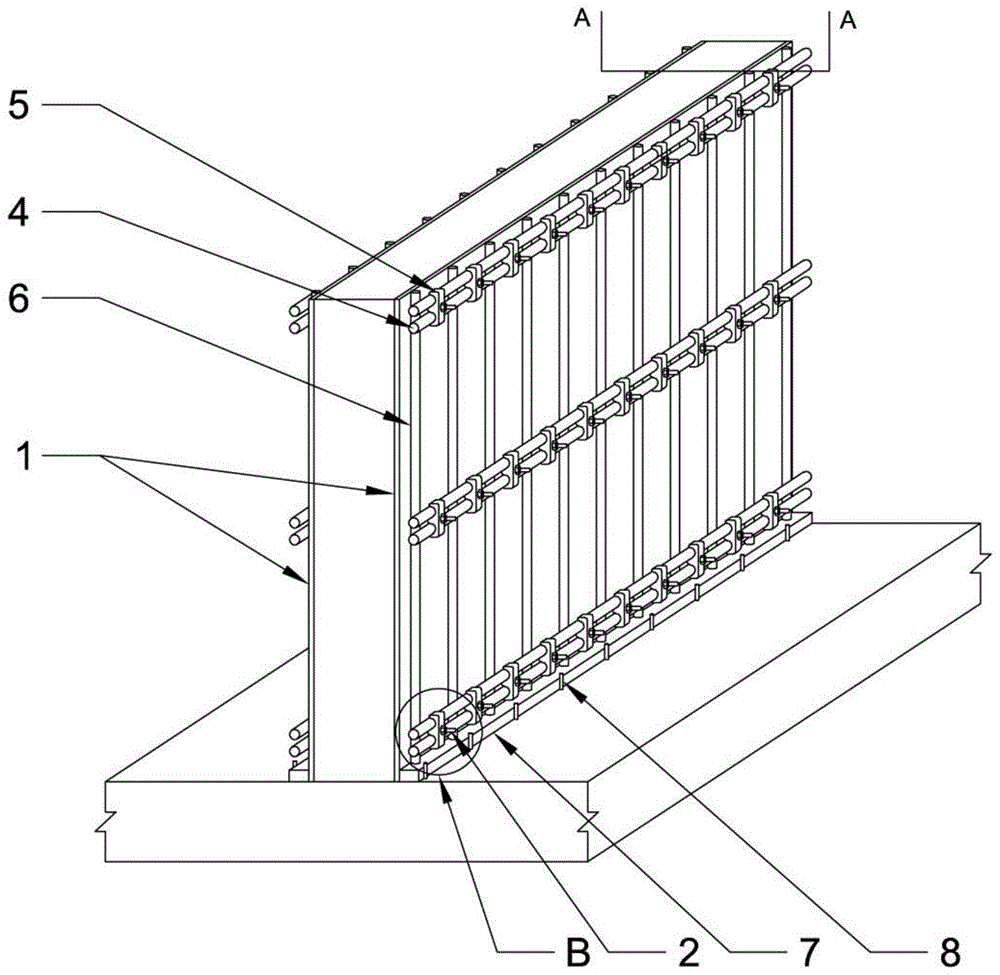
图1为本实用新型的结构示意图。Figure 1 is a schematic structural diagram of the utility model.
图2为图1中A-A的剖面结构示意图。FIG. 2 is a schematic cross-sectional structure diagram of A-A in FIG. 1 .
图3为图1中B的放大图。FIG. 3 is an enlarged view of B in FIG. 1 .
图4为模板的结构示意图。Figure 4 is a schematic diagram of the structure of the template.
图5为螺杆的结构示意图。Figure 5 is a schematic diagram of the structure of the screw.
主要元件符号说明如下:The main component symbols are explained as follows:
模板1、整块大模板11、带孔定制小模板12、螺杆2、杆体21、螺纹连接头22、紧固螺母3、横杆4、蝴蝶扣5、竖杆6、压条7、定位销8。
具体实施方式Detailed ways
下面将结合附图对本实用新型技术方案的实施例进行详细的描述。以下实施例仅用于更加清楚地说明本实用新型的技术方案,因此只作为示例,而不能以此来限制本实用新型的保护范围。The embodiments of the technical solutions of the present utility model will be described in detail below with reference to the accompanying drawings. The following embodiments are only used to illustrate the technical solutions of the present invention more clearly, and are therefore only used as examples, and cannot be used to limit the protection scope of the present invention.
需要注意的是,除非另有说明,本申请使用的技术术语或者科学术语应当为本实用新型所属领域技术人员所理解的通常意义。It should be noted that, unless otherwise specified, the technical or scientific terms used in the present application shall have the usual meanings understood by those skilled in the art to which the present invention belongs.
如图1、图2、图3、图4、图5所示,一种剪力墙大模板免钻孔加固系统,包括竖直设置于基面上的两个模板1,两个所述模板1之间构成用于浇筑剪力墙的模腔;两个所述模板1之间设置有若干螺杆2,若干所述螺杆2两端分别垂直穿透两个模板1,所述螺杆2两端分别套设有紧固螺母3;若干所述螺杆2分成横向设置的若干排,两个所述模板1向外一侧均设置有与若干排螺杆2对应的若干组紧固件,所述紧固件包括两个横杆4和与若干蝴蝶扣5,两个所述紧固件分别设置于单排螺杆2的上下两侧,若干所述蝴蝶扣5分别于单排中每个螺杆2端部套接,且通过紧固螺母3向内压紧。As shown in Fig. 1, Fig. 2, Fig. 3, Fig. 4, Fig. 5, a large formwork-free reinforcement system for shear wall includes two
本实施例中,两个模板1通过若干组紧固件的夹持配合将两个模板1构成的浇筑模腔进行定位,操作方便,且结构稳定,能够提高操作的便捷性的同时通过提高其自身的结构稳定性,提高浇筑墙体的质量。In this embodiment, the two
本实施例中,所述紧固件与模板1之间还设置有若干竖直设置的竖杆6,若干所述竖杆6底部设置有压条7,所述压条7与模板1底边平行设置,若干所述竖杆6下端均插入压条7内,压条7与模板1底边平行,则若干竖杆6与若干压条7将构成一个平行与模板1的平面,使紧固件对模板1挤压时,模板1受力更加均匀,板面更加平整,进一步提高墙体的浇筑质量。In this embodiment, a number of vertically arranged
本实施例中,所述压条7背离模板1一侧设置有若干定位销8,所述定位销8下端插入基面内,能够对压条7进行定位,提高整体结构稳定性。In this embodiment,
本实施例中,所述模板1由多个整块大模板11和多个带孔定制小模板12拼接构成,模块化组装便于施工。In this embodiment, the
本实施例中,所述螺杆2包括杆体21和两个螺纹连接头22,两个所述螺纹连接头22分别插入螺杆2两端,且通过螺纹配合连接,在拆除模板1时,只需要拆卸两端的螺纹连接头22,不用将螺杆2整体拆除,提高施工的便捷性。In this embodiment, the
最后应说明的是:以上各实施例仅用以说明本实用新型的技术方案,而非对其限制;尽管参照前述各实施例对本实用新型进行了详细的说明,本领域的普通技术人员应当理解:其依然可以对前述各实施例所记载的技术方案进行修改,或者对其中部分或者全部技术特征进行等同替换;而这些修改或者替换,并不使相应技术方案的本质脱离本实用新型各实施例技术方案的范围,其均应涵盖在本实用新型的权利要求和说明书的范围当中。Finally, it should be noted that the above embodiments are only used to illustrate the technical solutions of the present utility model, but not to limit them; although the present utility model has been described in detail with reference to the foregoing embodiments, those of ordinary skill in the art should understand that : it can still modify the technical solutions recorded in the foregoing embodiments, or perform equivalent replacements to some or all of the technical features; and these modifications or replacements do not make the essence of the corresponding technical solutions deviate from the various embodiments of the present utility model The scope of the technical solution should be covered by the scope of the claims and description of the present invention.
Claims (5)
Priority Applications (1)
| Application Number | Priority Date | Filing Date | Title |
|---|---|---|---|
| CN201921689329.8U CN211313369U (en) | 2019-10-10 | 2019-10-10 | Drilling-free reinforcing system for shear wall large template |
Applications Claiming Priority (1)
| Application Number | Priority Date | Filing Date | Title |
|---|---|---|---|
| CN201921689329.8U CN211313369U (en) | 2019-10-10 | 2019-10-10 | Drilling-free reinforcing system for shear wall large template |
Publications (1)
| Publication Number | Publication Date |
|---|---|
| CN211313369U true CN211313369U (en) | 2020-08-21 |
Family
ID=72080043
Family Applications (1)
| Application Number | Title | Priority Date | Filing Date |
|---|---|---|---|
| CN201921689329.8U Expired - Fee Related CN211313369U (en) | 2019-10-10 | 2019-10-10 | Drilling-free reinforcing system for shear wall large template |
Country Status (1)
| Country | Link |
|---|---|
| CN (1) | CN211313369U (en) |
Cited By (2)
| Publication number | Priority date | Publication date | Assignee | Title |
|---|---|---|---|---|
| CN112252465A (en) * | 2020-09-30 | 2021-01-22 | 晟通科技集团有限公司 | Construction method of formwork |
| CN113482328A (en) * | 2021-07-01 | 2021-10-08 | 广西建工集团控股有限公司 | Integral hoisting installation construction method for steel pipe template of outer shear wall |
-
2019
- 2019-10-10 CN CN201921689329.8U patent/CN211313369U/en not_active Expired - Fee Related
Cited By (2)
| Publication number | Priority date | Publication date | Assignee | Title |
|---|---|---|---|---|
| CN112252465A (en) * | 2020-09-30 | 2021-01-22 | 晟通科技集团有限公司 | Construction method of formwork |
| CN113482328A (en) * | 2021-07-01 | 2021-10-08 | 广西建工集团控股有限公司 | Integral hoisting installation construction method for steel pipe template of outer shear wall |
Similar Documents
| Publication | Publication Date | Title |
|---|---|---|
| CN206796130U (en) | A kind of concrete mold with reserving hole | |
| CN205915488U (en) | Reserve door and window pouring mold | |
| CN109808046B (en) | Bay window mold, bay window inner and outer mold components and bay window mold | |
| CN206599996U (en) | A kind of U-shaped reinforcement sectional material of aluminum wood template | |
| CN208686064U (en) | A kind of shear wall casting mold | |
| CN208020455U (en) | A kind of prefabricated slope protection concrete component production mould | |
| CN213654229U (en) | Adjustable post die special steel clamp | |
| CN207469741U (en) | A kind of making mold of reinforced concrete floor | |
| CN206114393U (en) | Shaping examination mould of preparation concrete sample | |
| CN209095903U (en) | A part injection mold based on core replacement | |
| CN204430017U (en) | A kind of mould fixed mechanism | |
| CN207878934U (en) | A kind of aluminum dipping form branch fastener | |
| CN211389324U (en) | Precast beam end installation mould | |
| CN210453466U (en) | A kind of anti-separation pressure molding die of foam composite board | |
| CN209533730U (en) | A kind of die assembly for prefabricated U-shaped component | |
| CN209425706U (en) | A kind of standardization fast changing shifts time latch structure of mold | |
| CN205096508U (en) | A cast first board for die casting machine or injection molding machine | |
| CN214364964U (en) | A plugging mold for aluminum film feed opening | |
| CN216757874U (en) | QS adsorbs integrative mould fixed establishment of side cut | |
| CN208629660U (en) | A kind of locking mold core component of brick-making mould | |
| CN214110803U (en) | Special-shaped brick mould for coke oven | |
| CN222178143U (en) | A brick-making mold that is easy to disassemble and assemble | |
| CN206678139U (en) | A kind of detachable cuboid test block mould for being easy to the demoulding | |
| CN222021844U (en) | A combined assembly prefabricated cover plate mold | |
| CN219544123U (en) | Deep cavity mould pressing die |
Legal Events
| Date | Code | Title | Description |
|---|---|---|---|
| GR01 | Patent grant | ||
| GR01 | Patent grant | ||
| CF01 | Termination of patent right due to non-payment of annual fee |
Granted publication date: 20200821 |
|
| CF01 | Termination of patent right due to non-payment of annual fee |