CN211286230U - A quick installation and disassembly of the ceiling installation structure - Google Patents
A quick installation and disassembly of the ceiling installation structure Download PDFInfo
- Publication number
- CN211286230U CN211286230U CN201921678171.4U CN201921678171U CN211286230U CN 211286230 U CN211286230 U CN 211286230U CN 201921678171 U CN201921678171 U CN 201921678171U CN 211286230 U CN211286230 U CN 211286230U
- Authority
- CN
- China
- Prior art keywords
- ceiling
- keel
- support rod
- installation
- hoist
- Prior art date
- Legal status (The legal status is an assumption and is not a legal conclusion. Google has not performed a legal analysis and makes no representation as to the accuracy of the status listed.)
- Expired - Fee Related
Links
Images


Landscapes
- Conveying And Assembling Of Building Elements In Situ (AREA)
Abstract
Description
技术领域technical field
本实用新型属于装饰建材领域,具体涉及一种快速安拆的天花板安装结构。The utility model belongs to the field of decorative building materials, in particular to a ceiling installation structure for quick installation and disassembly.
背景技术Background technique
天花板是一座建筑物室内顶部表面的地方。在室内设计中,天花板可以写画、油漆美化室内环境及安装吊灯、光管、吊扇、开天窗、装空调,改变室内照明及空气流通的效用。是对装饰室内屋顶材料的总称。过去传统民居中多以草席、苇席、木板等为主要材料。随着科技的进步更多的现代建筑材料被应用进来。The ceiling is where the top surface of a building's interior is. In interior design, the ceiling can be painted and painted to beautify the indoor environment and install chandeliers, light pipes, ceiling fans, open skylights, and install air conditioners to change the effectiveness of indoor lighting and air circulation. It is a general term for decorative indoor roofing materials. In the past, straw mats, reed mats and wooden boards were the main materials in traditional dwellings. With the advancement of technology, more modern building materials have been applied.
天花板吊顶是建筑材料领域内常见的产品,在诸多建筑的室内广泛应用。天花板吊顶的安装多采用龙骨结构,然后将天花板安装铺设在龙骨结构上,因而龙骨与天花板之间的安装结构设计会影响到天花板吊顶整体安装的便捷性与稳定性。Ceiling ceiling is a common product in the field of building materials and is widely used in many buildings. The keel structure is mostly used for the installation of the ceiling, and then the ceiling is installed and laid on the keel structure. Therefore, the design of the installation structure between the keel and the ceiling will affect the convenience and stability of the overall installation of the ceiling.
现有的天花板是依靠其弹性变形而产生的弹力实现与龙骨的卡紧,在多次变形或经过较长时间之后,其弹力会变小,进而影响到天花板与龙骨之间的卡紧力,容易导致天花板脱落;由于天花板是通过弹性变形实现与龙骨的卡紧,在安装时,需要对天花板施加一定的力,才能将天花板装入,安装不方便,当天花板或者天花板上部安装的其他部件出现故障时,拆卸天花板也相对比较困难。The existing ceiling relies on the elastic force generated by its elastic deformation to realize the clamping with the keel. After multiple deformations or after a long period of time, the elastic force will become smaller, which will affect the clamping force between the ceiling and the keel. It is easy to cause the ceiling to fall off; because the ceiling is clamped with the keel through elastic deformation, it is necessary to apply a certain force to the ceiling to install the ceiling, which is inconvenient to install. When the ceiling or other components installed on the upper part of the ceiling appear It is also relatively difficult to remove the ceiling in case of failure.
实用新型内容Utility model content
为了克服现有技术的缺陷,本实用新型所要解决的技术问题在于提出一种快速安拆的天花板安装结构,以解决背景技术中存在的问题。In order to overcome the defects of the prior art, the technical problem to be solved by the present invention is to propose a ceiling installation structure that can be quickly installed and dismantled, so as to solve the problems existing in the background technology.
为达此目的,本实用新型采用以下技术方案:For this purpose, the utility model adopts the following technical solutions:
本实用新型提供了一种快速安拆的天花板安装结构,包括吊装组件、上层龙骨、连接构件、下层龙骨和天花板,所述吊装组件通过膨胀螺钉与顶部墙面固定连接,所述上层龙骨水平横向排列且吊装于所述吊装组件的底部,所述下层龙骨水平纵向排列且通过所述连接构件吊装于所述上层龙骨之下,所述连接构件整体呈倒Y型,所述天花板可拆卸的安装在两相邻所述连接构件下吊装的所述下层龙骨上,所述天花板整体呈矩形,所述天花板上与顶部墙面垂直的四个侧面为半圆柱型,所述天花板上表面开设有通孔,所述天花板上表面与所述通孔同侧设置有挂板,所述通孔内部横向安装有支撑杆,所述支撑杆上套设有套筒,所述套筒与所述支撑杆滑动连接,所述套筒上设置有挂钩和推杆,所述挂钩伸出所述天花板上表面,所述推杆与所述天花板下表面齐平,所述挂钩和所述推杆在所述套筒上相对设置,所述支撑杆上套设有第一弹簧,所述第一弹簧设置在所述支撑杆上靠近所述挂板一端。The utility model provides a ceiling installation structure for quick installation and disassembly, which comprises a hoisting assembly, an upper keel, a connecting member, a lower keel and a ceiling. The hoisting assembly is fixedly connected to the top wall through expansion screws, and the upper keel is horizontal and horizontal Arranged and hoisted at the bottom of the hoisting assembly, the lower keel is arranged horizontally and longitudinally and is hoisted under the upper keel through the connecting member, the connecting member is an inverted Y shape as a whole, and the ceiling can be detachably installed On the lower keel hoisted under the two adjacent connecting members, the ceiling is rectangular as a whole, the four sides of the ceiling that are perpendicular to the top wall are semi-cylindrical, and the upper surface of the ceiling is provided with a through hole. The upper surface of the ceiling is provided with a hanging plate on the same side as the through hole, a support rod is installed laterally inside the through hole, and a sleeve is sleeved on the support rod, and the sleeve is connected to the support rod. Sliding connection, the sleeve is provided with a hook and a push rod, the hook protrudes from the upper surface of the ceiling, the push rod is flush with the lower surface of the ceiling, the hook and the push rod are in the The sleeves are oppositely arranged, the support rod is sleeved with a first spring, and the first spring is arranged on the support rod near one end of the hanging plate.
在本实用新型较佳的技术方案中,所述挂板与所述下层龙骨配合处设置为水平状,所述挂板设置宽度为所述天花板同向宽度的1/3~2/3。In a preferred technical solution of the present utility model, the cooperating part of the hanging plate and the lower keel is arranged horizontally, and the installation width of the hanging plate is 1/3~2/3 of the width of the ceiling in the same direction.
在本实用新型较佳的技术方案中,所述天花板上开设的第一凹槽内部靠近所述挂板一侧开设有第二凹槽,所述第二凹槽内部安装有第二弹簧。In a preferred technical solution of the present invention, a second groove is formed inside the first groove opened on the ceiling near the side of the hanging plate, and a second spring is installed inside the second groove.
在本实用新型较佳的技术方案中,所述支撑杆上靠近所述第二凹槽一端设置有挡板。In a preferred technical solution of the present invention, a baffle plate is provided on one end of the support rod close to the second groove.
在本实用新型较佳的技术方案中,所述天花板第一凹槽内部远离所述第二凹槽一侧设置有挡块,所述支撑杆上与所述挡块安装对应位置开设有容置槽,在所述挡块外侧与所述支撑杆之间设置有缓冲垫。In a preferred technical solution of the present invention, a block is provided inside the first groove of the ceiling away from the second groove, and a receiving block is provided on the support rod at a position corresponding to the installation of the block. a groove, and a buffer pad is arranged between the outer side of the block and the support rod.
在本实用新型较佳的技术方案中,所述推杆与所述天花板下表面之间连接有折叠板。In a preferred technical solution of the present invention, a folding plate is connected between the push rod and the lower surface of the ceiling.
本实用新型的有益效果为:The beneficial effects of the present utility model are:
本实用新型的一种快速安拆的天花板安装结构,吊装组件通过膨胀螺钉与顶部墙面固定连接,上层龙骨水平横向排列且吊装于吊装组件的底部,下层龙骨水平纵向排列且通过连接构件吊装于上层龙骨之下,天花板可拆卸的安装在下层龙骨上,天花板整体呈矩形,天花板上与顶部墙面垂直的四个侧面为半圆柱型,设置成半圆柱型的侧面能够减少各天花板在安装过程中的干涉,天花板上下表面开设有通孔,天花板上表面与通孔同侧设置有挂板,设置的挂板在安装的过程中可以卡住下层龙骨,省力的同时可以防止天花板翻转,通孔内部安装有支撑杆,支撑杆上套设有套筒,套筒与支撑杆滑动连接,套筒上设置有挂钩和推杆,挂钩伸出天花板上表面,推杆与天花板下表面齐平,挂钩和推杆在套筒上相对设置,支撑杆上套设有第一弹簧,第一弹簧设置在支撑杆上靠近挂板一端,第一弹簧对套筒产生推力,通过拨动推杆挤压第一弹簧,带动挂钩跟随套筒在支撑杆上滑动,当挂钩滑动距离超过下层龙骨时,向上推天花板,然后松推杆,在第一弹簧的回复力的作用下,挂钩复位,勾住下层龙骨。本实用新型设计的一种快速安拆的天花板安装结构可以方便的将天花板安装和拆下,操作简单,天花板安装稳定性高。The utility model provides a ceiling installation structure for quick installation and disassembly. The hoisting component is fixedly connected to the top wall through expansion screws, the upper keel is horizontally arranged horizontally and is hoisted at the bottom of the hoisting component, and the lower keel is horizontally and vertically arranged and is hoisted at the bottom of the hoisting component through connecting members. Under the upper keel, the ceiling is detachably installed on the lower keel. The ceiling is rectangular as a whole, and the four sides of the ceiling that are perpendicular to the top wall are semi-cylindrical. Setting the semi-cylindrical sides can reduce the installation process of each ceiling The upper and lower surfaces of the ceiling are provided with through holes, and the upper surface of the ceiling is provided with a hanging plate on the same side as the through hole. The installed hanging plate can clamp the lower keel during the installation process. A support rod is installed inside, a sleeve is sleeved on the support rod, the sleeve is slidably connected with the support rod, a hook and a push rod are arranged on the sleeve, the hook protrudes from the upper surface of the ceiling, the push rod is flush with the lower surface of the ceiling, and the hook It is arranged opposite to the push rod on the sleeve, the support rod is sleeved with a first spring, the first spring is arranged on the support rod near the end of the hanging plate, the first spring generates a thrust to the sleeve, and the first spring is pressed by pushing the push rod. A spring drives the hook to follow the sleeve to slide on the support rod. When the sliding distance of the hook exceeds the lower keel, the ceiling is pushed up, and then the push rod is released. Under the action of the restoring force of the first spring, the hook resets and hooks the lower keel. . The rapid installation and removal of the ceiling installation structure designed by the utility model can conveniently install and remove the ceiling, the operation is simple, and the ceiling installation stability is high.
附图说明Description of drawings
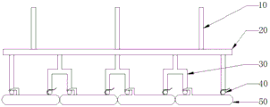
图1是本实用新型具体实施方式提供的一种快速安拆的天花板安装结构的整体结构示意图;Fig. 1 is the overall structure schematic diagram of a kind of quick installation and dismantling ceiling installation structure provided by the specific embodiment of the present invention;
图2是本实用新型具体实施方式提供的一种快速安拆的天花板安装结构的天花板结构示意图;2 is a schematic view of a ceiling structure of a quick-installed and disassembled ceiling installation structure provided by a specific embodiment of the present invention;
图3是本实用新型具体实施方式提供的一种快速安拆的天花板安装结构的A的局部放大图;3 is a partial enlarged view of A of a quick-installed and disassembled ceiling installation structure provided by a specific embodiment of the present invention;
图4是本实用新型具体实施方式提供的一种快速安拆的天花板安装结构的天花板俯视结构示意图;4 is a schematic top view of the ceiling structure of a quick-installed and dismantled ceiling installation structure provided by a specific embodiment of the present invention;
图5是本实用新型具体实施方式提供的一种快速安拆的天花板安装结构的天花板仰视结构示意图。FIG. 5 is a schematic view of a ceiling bottom view of a quick-installed and dismantled ceiling installation structure provided by a specific embodiment of the present invention.
图中:In the picture:
10、吊装组件;20、上层龙骨;30、连接构件;40、下层龙骨;50、天花板;501、通孔;502、挂板;503、支撑杆;5031、挡板;5032、容置槽;504、套筒;505、挂钩;506、推杆;507、第一弹簧;508、凹槽;509、第二弹簧;5010、挡块;5011、缓冲垫;5012、折叠板。10, hoisting assembly; 20, upper keel; 30, connecting member; 40, lower keel; 50, ceiling; 501, through hole; 502, hanging plate; 503, support rod; 5031, baffle; 5032, accommodating slot; 504, sleeve; 505, hook; 506, push rod; 507, first spring; 508, groove; 509, second spring;
具体实施方式Detailed ways
下面结合附图并通过具体实施方式来进一步说明本实用新型的技术方案。The technical solutions of the present utility model will be further described below with reference to the accompanying drawings and through specific embodiments.
在本实用新型的描述中,需要理解的是,术语“长度”、“宽度”、“上”、“下”、“前”、“后”、“左”、“右”、“竖直”、“水平”、“顶”、“底”“内”、“外”等指示的方位或位置关系为基于附图所示的方位或位置关系,仅是为了便于描述本实用新型和简化描述,而不是指示或暗示所指的装置或元件必须具有特定的方位、以特定的方位构造和操作,因此不能理解为对本实用新型的限制。In the description of the present invention, it should be understood that the terms "length", "width", "upper", "lower", "front", "rear", "left", "right", "vertical" , "horizontal", "top", "bottom", "inside", "outside" and other indicated orientations or positional relationships are based on the orientations or positional relationships shown in the accompanying drawings, only for the convenience of describing the present utility model and simplifying the description, Rather than indicating or implying that the indicated device or element must have a particular orientation, be constructed and operate in a particular orientation, it should not be construed as a limitation of the present invention.
此外,术语“第一”、“第二”仅用于描述目的,而不能理解为指示或暗示相对重要性或者隐含指明所指示的技术特征的数量。由此,限定有“第一”、“第二”的特征可以明示或者隐含地包括一个或者更多个该特征。在本实用新型的描述中,“多个”的含义是两个或两个以上,除非另有明确具体的限定。In addition, the terms "first" and "second" are only used for descriptive purposes, and should not be construed as indicating or implying relative importance or implying the number of indicated technical features. Thus, a feature defined as "first" or "second" may expressly or implicitly include one or more of that feature. In the description of the present invention, "plurality" means two or more, unless otherwise expressly and specifically defined.
在本实用新型中,除非另有明确的规定和限定,术语“安装”、“相连”、“连接”、“固定”等术语应做广义理解,例如,可以是固定连接,也可以是可拆卸连接,或成一体;可以是机械连接,也可以是电连接;可以是直接相连,也可以通过中间媒介间接相连,可以是两个元件内部的连通或两个元件的相互作用关系。对于本领域的普通技术人员而言,可以根据具体情况理解上述术语在本实用新型中的具体含义。In the present utility model, unless otherwise expressly specified and limited, the terms "installation", "connection", "connection", "fixed" and other terms should be understood in a broad sense, for example, it may be a fixed connection or a detachable connection Connection, or integration; it can be a mechanical connection or an electrical connection; it can be a direct connection or an indirect connection through an intermediate medium, and it can be the internal communication between the two elements or the interaction relationship between the two elements. For those of ordinary skill in the art, the specific meanings of the above terms in the present invention can be understood according to specific situations.
图1-5实例性的示出了本实用新型提供的一种快速安拆的天花板安装结构,包括吊装组件10、上层龙骨20、连接构件30、下层龙骨40和天花板50,所述吊装组件10通过膨胀螺钉与顶部墙面固定连接,所述上层龙骨20水平横向排列且吊装于所述吊装组件10的底部,所述下层龙骨40水平纵向排列且通过所述连接构件30吊装于所述上层龙骨20之下,所述连接构件30整体呈倒Y型,所述天花板50可拆卸的安装在两相邻所述连接构件30下吊装的所述下层龙骨40上,所述天花板50整体呈矩形,所述天花板50上与顶部墙面垂直的四个侧面为半圆柱型,所述天花板50上表面开设有通孔501,所述天花板50上表面与所述通孔501同侧设置有挂板502,所述通孔501内部横向安装有支撑杆503,所述支撑杆503上套设有套筒504,所述套筒504与所述支撑杆503滑动连接,所述套筒504上设置有挂钩505和推杆506,所述挂钩505伸出所述天花板50上表面,所述推杆506与所述天花板50下表面齐平,所述挂钩505和所述推杆506在所述套筒504上相对设置,所述支撑杆503上套设有第一弹簧507,所述第一弹簧507设置在所述支撑杆503上靠近所述挂板502一端。1-5 exemplarily show a quick-installed ceiling installation structure provided by the present invention, including a
以上实施,具体来说,首先将所述下层龙骨40插入所述天花板50的所述挂板502内部,由于所述第一弹簧507受到挤压对所述套筒504产生推力,通过拨动所述推杆506挤压所述第一弹簧507,带动所述挂钩505跟随所述套筒504在所述支撑杆503上滑动,当所述挂钩505滑动距离超过所述下层龙骨40时,向上推所述天花板50,然后松开所述推杆506,在所述第一弹簧507的回复力的作用下,所述挂钩505复位,勾住所述下层龙骨40。In the above implementation, specifically, the
可选的,所述挂板502与所述下层龙骨40配合处设置为水平状,所述挂板502设置宽度为所述天花板50纵向宽度的1/3~2/3,优选所述挂板502设置宽度为所述天花板50纵向宽度的1/2,所述天花板50安装稳定性高。Optionally, the place where the
优选地,所述天花板50上开设的所述通孔501内部靠近所述挂板502一侧开设有凹槽508,所述凹槽508内部安装有第二弹簧509,设置的所述第二弹簧509能够便于安装所述支撑杆503,而且能够确保所述支撑杆503安装牢靠。Preferably, a
优选地,所述支撑杆503上靠近所述凹槽508一端设置有挡板5031,设置的所述挡板5031能够对所述第一弹簧507进行限位。Preferably, a
优选地,所述天花板50开设的所述通孔501内部远离所述凹槽508一侧设置有挡块5010,所述支撑杆503上与所述挡块5010安装对应位置开设有容置槽5032,在所述挡块5010外侧与所述支撑杆503之间设置有缓冲垫5011,设置的所述挡块5010以及所述容置槽5032能够进一步提高所述支撑杆503与所述通孔501之间安装的稳定牢靠性,设置的所述缓冲垫5011能够缓冲所述支撑杆503安装过程中的压力。Preferably, a
优选地,所述推杆506与所述天花板50下表面之间连接有折叠板5012,防止顶部墙面与所述天花板50之间的杂物灰尘掉落。Preferably, a
本实用新型是通过优选实施例进行描述的,本领域技术人员知悉,在不脱离本实用新型的精神和范围的情况下,可以对这些特征和实施例进行各种改变或等效替换。本实用新型不受此处所公开的具体实施例的限制,其他落入本申请的权利要求内的实施例都属于本实用新型保护的范围。The present invention is described by preferred embodiments, and those skilled in the art know that various changes or equivalent substitutions can be made to these features and embodiments without departing from the spirit and scope of the present invention. The present invention is not limited by the specific embodiments disclosed herein, and other embodiments falling within the claims of the present application all belong to the protection scope of the present invention.
Claims (6)
Priority Applications (1)
| Application Number | Priority Date | Filing Date | Title |
|---|---|---|---|
| CN201921678171.4U CN211286230U (en) | 2019-10-09 | 2019-10-09 | A quick installation and disassembly of the ceiling installation structure |
Applications Claiming Priority (1)
| Application Number | Priority Date | Filing Date | Title |
|---|---|---|---|
| CN201921678171.4U CN211286230U (en) | 2019-10-09 | 2019-10-09 | A quick installation and disassembly of the ceiling installation structure |
Publications (1)
| Publication Number | Publication Date |
|---|---|
| CN211286230U true CN211286230U (en) | 2020-08-18 |
Family
ID=72018359
Family Applications (1)
| Application Number | Title | Priority Date | Filing Date |
|---|---|---|---|
| CN201921678171.4U Expired - Fee Related CN211286230U (en) | 2019-10-09 | 2019-10-09 | A quick installation and disassembly of the ceiling installation structure |
Country Status (1)
| Country | Link |
|---|---|
| CN (1) | CN211286230U (en) |
Cited By (3)
| Publication number | Priority date | Publication date | Assignee | Title |
|---|---|---|---|---|
| CN112095894A (en) * | 2020-09-29 | 2020-12-18 | 金螳螂精装科技(苏州)有限公司 | Adjustable mounting structure of modular ceiling suspended top beam |
| CN112982798A (en) * | 2021-02-24 | 2021-06-18 | 上海梵辰空间设计工程有限公司 | Modular ceiling grade falling device and installation method |
| CN113417396A (en) * | 2021-06-04 | 2021-09-21 | 圣雅建设集团股份有限公司 | Suspended ceiling structure |
-
2019
- 2019-10-09 CN CN201921678171.4U patent/CN211286230U/en not_active Expired - Fee Related
Cited By (4)
| Publication number | Priority date | Publication date | Assignee | Title |
|---|---|---|---|---|
| CN112095894A (en) * | 2020-09-29 | 2020-12-18 | 金螳螂精装科技(苏州)有限公司 | Adjustable mounting structure of modular ceiling suspended top beam |
| CN112982798A (en) * | 2021-02-24 | 2021-06-18 | 上海梵辰空间设计工程有限公司 | Modular ceiling grade falling device and installation method |
| CN112982798B (en) * | 2021-02-24 | 2022-05-03 | 上海梵辰空间设计工程有限公司 | Modular ceiling grade falling device and installation method |
| CN113417396A (en) * | 2021-06-04 | 2021-09-21 | 圣雅建设集团股份有限公司 | Suspended ceiling structure |
Similar Documents
| Publication | Publication Date | Title |
|---|---|---|
| CN110761514B (en) | A decorative panel installation structure and installation method thereof | |
| CN110424664B (en) | A wall decorative panel assembly and wall decorative panel installation method | |
| CN208105738U (en) | A kind of dismountable decorative wall panels | |
| CN111851910A (en) | A wall-integrated board-back hanging system and installation method | |
| CN211114337U (en) | Suspended green building ceiling | |
| CN210917906U (en) | Detachable ceiling edge keel system | |
| CN210685093U (en) | Quick installation mechanism of curtain | |
| CN213233927U (en) | Building concatenation type curtain | |
| CN208586805U (en) | A kind of ceiling | |
| CN211447568U (en) | An indoor and outdoor soundproof decorative wall panel installation structure | |
| CN217949495U (en) | Double-layer suspended ceiling connecting mechanism with support structure | |
| CN214144252U (en) | Assembled partition wall fossil fragments frame and partition wall | |
| CN205189199U (en) | Suspended ceiling keel articulates piece | |
| CN219451184U (en) | Curtain binding off structure convenient to adjust | |
| CN210967745U (en) | Waste plate nail taking device for building construction | |
| CN216974003U (en) | But decoration wallboard of fast-assembling that installation quality is good | |
| CN109386080B (en) | A curtain wall sunshade installation structure | |
| CN216840176U (en) | An anti-deformation decorative ceiling | |
| CN217517887U (en) | Assembled curtain wall | |
| CN206530841U (en) | A kind of TV set rack for being easy to hanging TV into wall | |
| CN207363093U (en) | Fixing device for lining and ceiling board | |
| CN218714574U (en) | A wall-mounted sound insulation board installation structure | |
| CN222701279U (en) | Brick curtain wall dry hanging structure | |
| CN220451143U (en) | Honeycomb type quick installation sound insulation board | |
| CN205935316U (en) | Glass clamp for partition wall |
Legal Events
| Date | Code | Title | Description |
|---|---|---|---|
| GR01 | Patent grant | ||
| GR01 | Patent grant | ||
| CF01 | Termination of patent right due to non-payment of annual fee |
Granted publication date: 20200818 |
|
| CF01 | Termination of patent right due to non-payment of annual fee |