CN211277987U - Jig for processing punch - Google Patents
Jig for processing punch Download PDFInfo
- Publication number
- CN211277987U CN211277987U CN201922274411.0U CN201922274411U CN211277987U CN 211277987 U CN211277987 U CN 211277987U CN 201922274411 U CN201922274411 U CN 201922274411U CN 211277987 U CN211277987 U CN 211277987U
- Authority
- CN
- China
- Prior art keywords
- seat
- base
- annular
- end surface
- support column
- Prior art date
- Legal status (The legal status is an assumption and is not a legal conclusion. Google has not performed a legal analysis and makes no representation as to the accuracy of the status listed.)
- Expired - Fee Related
Links
- 238000004080 punching Methods 0.000 claims abstract description 19
- 238000003466 welding Methods 0.000 claims description 12
- 238000000034 method Methods 0.000 description 8
- 238000003754 machining Methods 0.000 description 2
- 230000009286 beneficial effect Effects 0.000 description 1
- 239000002184 metal Substances 0.000 description 1
Images



Landscapes
- Perforating, Stamping-Out Or Severing By Means Other Than Cutting (AREA)
Abstract
The utility model discloses a tool is used in punching pin processing, the on-line screen storage device comprises a base, the upper end surface of base is provided with V type seat, V type seat includes the guide way and connects in inboard annular limiting plate, annular limiting plate's front end surface is provided with first bolt, annular spout has been seted up to the upper end surface of base, the inboard of annular spout is connected with adjusts the seat, the upper end surface of adjusting the seat is connected with the support column. A tool is used in punching pin processing, through being provided with V type seat and support column, can carry out horizontal and vertical centre gripping to the punching pin, increase the variety of the centre gripping mode of tool is used in punching pin processing, it is more convenient during the use, through being provided with the regulation seat, utilize the cooperation of adjusting between seat and the base, can adjust the direction of support column for punching pin processing is more convenient.
Description
Technical Field
The utility model relates to a tool technical field, in particular to tool is used in punching pin processing.
Background
The punch is a punching tool made of metal, and can punch blanks on being fixed in corresponding tools, and the punch is durable and durable, so that the punch is convenient to use, and becomes an indispensable punching tool in machining, and the punch needs to be fixed by a jig in the machining process, and is convenient to polish and machine.
SUMMERY OF THE UTILITY MODEL
The utility model discloses a main aim at provides a tool is used in punching pin processing can effectively solve the problem in the background art.
In order to achieve the above purpose, the utility model adopts the following technical scheme:
the utility model provides a tool is used in punching pin processing, includes the base, the upper end surface of base is provided with V type seat, V type seat includes the guide way and connects in inboard annular limiting plate, annular limiting plate's front end surface is provided with first bolt, annular spout has been seted up to the upper end surface of base, the inboard of annular spout is connected with adjusts the seat, the upper end surface of adjusting the seat is connected with the support column.
Preferably, be provided with the welding rod between V type seat and the base, through welding rod fixed connection between V type seat and the base, the guide way is seted up in the both sides surface of V type seat, the guide way runs through in the surface of V type seat, through guide way sliding connection between ring limit board and the V type seat, be threaded connection between first bolt and the ring limit board.
Preferably, the annular chute runs through in the upper end surface of base, the surface of base is close to annular chute department and is provided with the bearing, be swing joint between bearing and the base, the lower extreme surface of base is provided with the connecting plate, the bottom of connecting plate embedding base, be fixed connection between connecting plate and the base.
Preferably, adjust the seat and include annular slide and spliced pole, the lower extreme surface of adjusting the seat is located to the annular slide, annular slide and adjusting are provided with the welding rod between the seat, through welding rod fixed connection between annular slide and the regulation seat, the spliced pole sets up and is close to annular slide inboard in the lower extreme surface of adjusting the seat, be fixed connection between spliced pole and the regulation seat, adjust and be swing joint between seat and the base.
Preferably, the upper end of support column has seted up the constant head tank for the surface, the constant head tank runs through in the surface of support column, the upper end surface of support column is provided with the second bolt, the second bolt runs through in the constant head tank, be threaded connection between second bolt and the support column, be fixed connection between support column and the regulation seat.
Compared with the prior art, the utility model discloses following beneficial effect has: the jig for processing the punch is characterized in that the V-shaped seat and the supporting column are arranged, the punch is placed on the surface of the V-shaped seat in the vertical direction, the annular limiting plate is slid to enable the annular limiting plate to be at a proper height, the first bolt on the surface of the annular limiting plate is screwed down to fix the punch and process the punch, when the clamping mode of the punch needs to be adjusted, the punch is taken down from the surface of the V-shaped seat and is transversely placed in the positioning groove on the surface of the supporting column, the punch is fixed by the second bolt to prevent the punch from falling off in the processing process, the clamping operation process is simple, time and labor are saved, different clamping modes of the punch can be met, the punch can be processed conveniently, the adjusting seat is rotated when the processing direction of the punch needs to be adjusted in the processing process of the punch, the annular sliding plate on the outer surface of the lower end of the adjusting seat slides along the annular sliding groove on the, the support column that drives the seat upper end of adjusting rotates together with the punching pin, adjusts the punching pin to suitable angle, utilizes and adjusts the seat, can adjust the angle of processing of punching pin wantonly, can improve the punching pin and the processing progress, improves processingquality.
Drawings
Fig. 1 is a schematic view of the overall structure of a jig for processing punches according to the present invention;
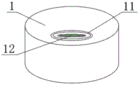
FIG. 2 is a schematic view of a base structure of a jig for punch processing according to the present invention;
FIG. 3 is a schematic view of a V-shaped seat structure of a jig for punch processing according to the present invention;
fig. 4 is a cross-sectional view of the adjusting seat and the base of the jig for processing punch of the present invention.
In the figure: 1. a base; 11. an annular chute; 12. a bearing; 13. a connecting plate; 2. a V-shaped seat; 21. a guide groove; 22. an annular limiting plate; 23. a first bolt; 3. an adjusting seat; 31. an annular slide plate; 32. connecting columns; 4. a support pillar; 41. positioning a groove; 42. and a second bolt.
Detailed Description
In order to make the technical means, creation features, achievement purposes and functions of the present invention easy to understand, the present invention is further described below with reference to the following embodiments.
As shown in fig. 1-4, a jig for processing punches comprises a base 1, wherein a V-shaped seat 2 is arranged on the outer surface of the upper end of the base 1, the V-shaped seat 2 comprises a guide groove 21 and an annular limiting plate 22 connected to the inner side of the guide groove, a first bolt 23 is arranged on the outer surface of the front end of the annular limiting plate 22, an annular chute 11 is formed in the outer surface of the upper end of the base 1, an adjusting seat 3 is connected to the inner side of the annular chute 11, and a supporting column 4 is connected to the outer surface of the upper end of.
Welding rods are arranged between the V-shaped seat 2 and the base 1, the V-shaped seat 2 and the base 1 are fixedly connected through the welding rods, the guide grooves 21 are formed in the outer surfaces of the two sides of the V-shaped seat 2, the guide grooves 21 penetrate through the outer surface of the V-shaped seat 2, the annular limiting plate 22 and the V-shaped seat 2 are connected in a sliding mode through the guide grooves 21, the first bolt 23 is in threaded connection with the annular limiting plate 22, and the first bolt 23 can be screwed conveniently;
the annular chute 11 penetrates through the outer surface of the upper end of the base 1, a bearing 12 is arranged on the outer surface of the base 1 close to the annular chute 11, the bearing 12 is movably connected with the base 1, a connecting plate 13 is arranged on the outer surface of the lower end of the base 1, the connecting plate 13 is embedded into the bottom end of the base 1, the connecting plate 13 is fixedly connected with the base 1, and firmness between the connecting plate 13 and the base 1 is improved;
the adjusting seat 3 comprises an annular sliding plate 31 and a connecting column 32, the annular sliding plate 31 is arranged on the outer surface of the lower end of the adjusting seat 3, a welding rod is arranged between the annular sliding plate 31 and the adjusting seat 3, the annular sliding plate 31 is fixedly connected with the adjusting seat 3 through the welding rod, the connecting column 32 is arranged on the outer surface of the lower end of the adjusting seat 3 and close to the inner side of the annular sliding plate 31, the connecting column 32 is fixedly connected with the adjusting seat 3, the adjusting seat 3 is movably connected with the base 1, and the adjusting seat 3 is convenient to rotate;
the constant head tank 41 has been seted up for the surface to the upper end of support column 4, and constant head tank 41 runs through in the surface of support column 4, and the upper end surface of support column 4 is provided with second bolt 42, and second bolt 42 runs through in constant head tank 41, is threaded connection between second bolt 42 and the support column 4, is fixed connection between support column 4 and the regulation seat 3.
It should be noted that the utility model relates to a jig for processing a punch, when in use, a user places the punch on the surface of a V-shaped seat 2 in the vertical direction, slides an annular limiting plate 22 to make the annular limiting plate 22 at a proper height, then screws a first bolt 23 on the surface of the annular limiting plate 22 to fix the punch and process the punch, when the clamping mode of the punch needs to be adjusted, the user takes the punch off the surface of the V-shaped seat 2 and transversely places the punch in a positioning groove 41 on the surface of a supporting column 4, the punch is fixed by a second bolt 42 to prevent the punch from falling off in the processing process, the clamping operation process is simple, time and labor are saved, different clamping modes of the punch can be met, the processing of the punch is facilitated, when the processing direction of the punch needs to be adjusted in the processing process of the punch, the user rotates an adjusting seat 3, an annular sliding plate 31 on the outer surface of the lower end of the adjusting seat 3 slides along an annular sliding groove 11 on the outer surface of the, the support column 4 that drives the upper end of adjusting seat 3 rotates with the punching pin together, adjusts the punching pin to suitable angle, utilizes and adjusts seat 3, can adjust the processing angle of punching pin wantonly, can improve the punching pin and the processing progress, improves processingquality.
The basic principles and the main features of the invention and the advantages of the invention have been shown and described above. It will be understood by those skilled in the art that the present invention is not limited to the above embodiments, and that the foregoing embodiments and descriptions are provided only to illustrate the principles of the present invention without departing from the spirit and scope of the present invention. The scope of the invention is defined by the appended claims and equivalents thereof.
Claims (5)
1. The utility model provides a tool is used in punching pin processing, includes base (1), its characterized in that: the utility model discloses a V type seat, including base (1), V type seat (2), ring chute (11) have been seted up to the upper end surface of base (1), the upper end surface of base (1) is provided with V type seat (2), V type seat (2) include guide way (21) and connect in inboard ring limiting plate (22), the front end surface of ring limiting plate (22) is provided with first bolt (23), ring chute (11) have been seted up to the upper end surface of base (1), the inboard of ring chute (11) is connected with adjusts seat (3), the upper end surface of adjusting seat (3) is connected with support.
2. The jig for processing a punch according to claim 1, wherein: be provided with the welding rod between V type seat (2) and base (1), through welding rod fixed connection between V type seat (2) and base (1), the both sides surface in V type seat (2) is seted up in guide way (21), guide way (21) run through in the surface of V type seat (2), through guide way (21) sliding connection between annular limiting plate (22) and V type seat (2), be threaded connection between first bolt (23) and annular limiting plate (22).
3. The jig for processing a punch according to claim 1, wherein: annular spout (11) run through in the upper end surface of base (1), the surface of base (1) is close to annular spout (11) department and is provided with bearing (12), be swing joint between bearing (12) and base (1), the lower extreme surface of base (1) is provided with connecting plate (13), the bottom of base (1) is embedded in connecting plate (13), be fixed connection between connecting plate (13) and base (1).
4. The jig for processing a punch according to claim 1, wherein: adjust seat (3) including annular slide (31) and spliced pole (32), the lower extreme surface of adjusting seat (3) is located in annular slide (31), annular slide (31) and adjust and be provided with the welding rod between seat (3), annular slide (31) and adjust and pass through welding rod fixed connection between seat (3), spliced pole (32) set up and are close to annular slide (31) inboard in the lower extreme surface of adjusting seat (3), be fixed connection between spliced pole (32) and the regulation seat (3), adjust and be swing joint between seat (3) and base (1).
5. The jig for processing a punch according to claim 1, wherein: for the surface constant head tank (41) has been seted up to the upper end of support column (4), constant head tank (41) run through in the surface of support column (4), the upper end surface of support column (4) is provided with second bolt (42), second bolt (42) run through in constant head tank (41), be threaded connection between second bolt (42) and support column (4), be fixed connection between support column (4) and regulation seat (3).
Priority Applications (1)
| Application Number | Priority Date | Filing Date | Title |
|---|---|---|---|
| CN201922274411.0U CN211277987U (en) | 2019-12-18 | 2019-12-18 | Jig for processing punch |
Applications Claiming Priority (1)
| Application Number | Priority Date | Filing Date | Title |
|---|---|---|---|
| CN201922274411.0U CN211277987U (en) | 2019-12-18 | 2019-12-18 | Jig for processing punch |
Publications (1)
| Publication Number | Publication Date |
|---|---|
| CN211277987U true CN211277987U (en) | 2020-08-18 |
Family
ID=72032494
Family Applications (1)
| Application Number | Title | Priority Date | Filing Date |
|---|---|---|---|
| CN201922274411.0U Expired - Fee Related CN211277987U (en) | 2019-12-18 | 2019-12-18 | Jig for processing punch |
Country Status (1)
| Country | Link |
|---|---|
| CN (1) | CN211277987U (en) |
Cited By (2)
| Publication number | Priority date | Publication date | Assignee | Title |
|---|---|---|---|---|
| CN114918332A (en) * | 2022-07-21 | 2022-08-19 | 歌尔股份有限公司 | Calibration tool, machine tool and calibration method |
| CN119328672A (en) * | 2024-11-07 | 2025-01-21 | 江苏锐之利智能科技有限公司 | Cutting tool processing tool |
-
2019
- 2019-12-18 CN CN201922274411.0U patent/CN211277987U/en not_active Expired - Fee Related
Cited By (3)
| Publication number | Priority date | Publication date | Assignee | Title |
|---|---|---|---|---|
| CN114918332A (en) * | 2022-07-21 | 2022-08-19 | 歌尔股份有限公司 | Calibration tool, machine tool and calibration method |
| CN114918332B (en) * | 2022-07-21 | 2022-11-01 | 歌尔股份有限公司 | Calibration tool, machine tool and calibration method |
| CN119328672A (en) * | 2024-11-07 | 2025-01-21 | 江苏锐之利智能科技有限公司 | Cutting tool processing tool |
Similar Documents
| Publication | Publication Date | Title |
|---|---|---|
| CN217669041U (en) | Novel metallurgical jig | |
| CN108746382A (en) | The corner brace of solar component aluminum frame is installed and riveting point processing tool | |
| CN213998420U (en) | Automatic pipe welding equipment | |
| CN217800370U (en) | Tool applicable to machining of steel pipes of different specifications | |
| CN202571818U (en) | Workbench adjustable in angle | |
| CN217168066U (en) | A fixed tool for grinding machine | |
| CN213381011U (en) | Universal round brush burring equipment | |
| CN215846088U (en) | Chamfering device for baffle plate of pressure container | |
| CN215999509U (en) | Public bottom plate frock of machining center | |
| CN216371792U (en) | Multifunctional clamp convenient to adjust and used for machining of mechanical parts | |
| CN212794717U (en) | Die blank pressing mechanism with height adjustable along with die blank | |
| CN214979369U (en) | A workpiece fixing device for machining | |
| CN212733819U (en) | Hyperbolic bridge arc planking die mould equipment | |
| CN211758695U (en) | Free adjusting clamp of radial drilling machine | |
| CN218533286U (en) | Pipe welding machine | |
| CN215787069U (en) | Processing and cutting equipment for producing metal frame | |
| CN207887948U (en) | A kind of multi-head milling machine | |
| CN208288840U (en) | The corner brace of solar component aluminum frame short side installs riveting point seat | |
| CN206464629U (en) | Desk-top automatic flat-plate chamfering machine | |
| CN217668872U (en) | Novel clamping device | |
| CN213733491U (en) | Laser and ultrasonic plastic seamless welding clamp | |
| CN222711935U (en) | Positioning and compacting tool | |
| CN217142842U (en) | Sheet metal welding positioning fixture | |
| CN212470292U (en) | Welding set for electrical engineering | |
| CN210306107U (en) | Tapping machine convenient to adjust |
Legal Events
| Date | Code | Title | Description |
|---|---|---|---|
| GR01 | Patent grant | ||
| GR01 | Patent grant | ||
| CF01 | Termination of patent right due to non-payment of annual fee |
Granted publication date: 20200818 |
|
| CF01 | Termination of patent right due to non-payment of annual fee |