CN211271759U - Foldable electric wheelchair - Google Patents
Foldable electric wheelchair Download PDFInfo
- Publication number
- CN211271759U CN211271759U CN201921609086.2U CN201921609086U CN211271759U CN 211271759 U CN211271759 U CN 211271759U CN 201921609086 U CN201921609086 U CN 201921609086U CN 211271759 U CN211271759 U CN 211271759U
- Authority
- CN
- China
- Prior art keywords
- assembly
- subassembly
- pipe
- lower support
- handrail
- Prior art date
- Legal status (The legal status is an assumption and is not a legal conclusion. Google has not performed a legal analysis and makes no representation as to the accuracy of the status listed.)
- Active
Links
- 230000000712 assembly Effects 0.000 claims description 9
- 238000000429 assembly Methods 0.000 claims description 9
- 230000003014 reinforcing effect Effects 0.000 claims description 7
- 238000003466 welding Methods 0.000 claims description 6
- 239000011111 cardboard Substances 0.000 claims description 5
- 230000009471 action Effects 0.000 abstract description 2
- 230000008901 benefit Effects 0.000 abstract description 2
- 210000005069 ears Anatomy 0.000 description 5
- 230000000694 effects Effects 0.000 description 4
- 239000000725 suspension Substances 0.000 description 4
- 230000001105 regulatory effect Effects 0.000 description 3
- 238000009434 installation Methods 0.000 description 2
- 230000007246 mechanism Effects 0.000 description 2
- 238000000034 method Methods 0.000 description 2
- 230000004048 modification Effects 0.000 description 2
- 238000012986 modification Methods 0.000 description 2
- 230000002787 reinforcement Effects 0.000 description 2
- 238000007493 shaping process Methods 0.000 description 2
- 230000009286 beneficial effect Effects 0.000 description 1
- 230000000903 blocking effect Effects 0.000 description 1
- 230000007547 defect Effects 0.000 description 1
- 230000001771 impaired effect Effects 0.000 description 1
- 230000006872 improvement Effects 0.000 description 1
- NJPPVKZQTLUDBO-UHFFFAOYSA-N novaluron Chemical compound C1=C(Cl)C(OC(F)(F)C(OC(F)(F)F)F)=CC=C1NC(=O)NC(=O)C1=C(F)C=CC=C1F NJPPVKZQTLUDBO-UHFFFAOYSA-N 0.000 description 1
- 230000002265 prevention Effects 0.000 description 1
- 230000008569 process Effects 0.000 description 1
Images




Landscapes
- Handcart (AREA)
Abstract
The utility model belongs to the technical field of electronic wheelchair, especially, be a collapsible electronic wheelchair, including side bearer subassembly, front wheel subassembly, pedal subassembly, back subassembly, seat frame subassembly, handrail subassembly, control subassembly, rear wheel subassembly, prevent turning over subassembly, battery pack, control box. The utility model discloses a structure to current electronic wheelchair improves, utilizes the back subassembly to do the utility model discloses a locking position to through being divided into the back subassembly, go up leaning on subassembly and locking Assembly three, wherein the lower support subassembly with go up leaning on the subassembly for articulated, can take place relatively and rotate, nevertheless lock through locking Assembly and played the fixed action, thereby it is right the utility model discloses when folding, mainly open locking Assembly, stimulate the back of the lower support subassembly hypsokinesis and can accomplish folding work, have folding simple step and the fast advantage of folding speed, it is equally convenient to convert the user state into from fold condition.
Description
Technical Field
The utility model relates to an electric wheelchair technical field specifically is a collapsible electric wheelchair.
Background
Electric wheelchair vehicles, also referred to simply as electric wheelchairs, are tools for special groups of people such as disabled persons, elderly people, people with mobility difficulties, physically impaired persons and patients for medical clinical rehabilitation to walk instead. The macrostructure of an electric wheelchair is well known, and specifically comprises a vehicle body and an electric mechanism, wherein the vehicle body comprises a frame, wheels, a chair seat, a chair back, an armrest and the like, and the electric mechanism comprises a driving motor, a power supply, a control handle, a controller and the like. Technical information on electric wheelchair vehicles, such as grant publication numbers CN106074028B (foldable electric wheelchair), CN104800009B (front-folding and anti-tipping electric wheelchair), CN102755230B (electric wheelchair), and CN107049632B (light-weight portable electric wheelchair), is not known in the prior published chinese patent documents.
Present electric wheelchair all designs into collapsible type for can conveniently carrying, accomodating, transportation and storage, nevertheless because electric wheelchair's component is many, in order to guarantee the stability of structure, can design a plurality of retaining members, takes off the retaining member among the folding process, then accomplishes folding operation, but can cause electric wheelchair's folding step loaded down with trivial details, can't accomplish folding operation fast, equally can't convert folded state into user state fast, consequently need improve prior art, the utility model discloses the people proposes and has done profitable design, has formed the technical scheme that will introduce below.
SUMMERY OF THE UTILITY MODEL
Technical problem to be solved
Aiming at the defects of the prior art, the utility model provides a foldable electric wheelchair, which solves the problems in the prior art.
(II) technical scheme
In order to achieve the above object, the utility model provides a following technical scheme: a foldable electric wheelchair comprises a side frame assembly, a front wheel assembly, a pedal assembly, a backrest assembly, a seat frame assembly, a handrail assembly, a control assembly, a rear wheel assembly, an anti-turnover assembly, a battery assembly and a control box, wherein the backrest assembly consists of a lower support assembly, an upper leaning assembly and a locking assembly.
The inner side of one end of the side frame component is hinged with the front wheel component and the seat frame component.
The front wheel assembly is hinged with the pedal assembly.
The inner side of the other end of the side frame component is hinged with the lower support component and is connected with the rear wheel component through a bolt.
The top of the lower support assembly and the bottom of the upper leaning assembly are hinged and can be detachably fixed through a locking assembly.
The locking assembly is fixed to the top of the lower support assembly.
The seat frame assembly is hinged with the upper leaning assembly.
The armrest assembly is hinged with the seat frame assembly and the upper leaning assembly.
The control assembly is detachably fixed on the armrest assembly.
The rear wheel assembly is fixed to the rear side of the side frame assembly.
The anti-overturning assembly is detachably fixed on the rear wheel assembly.
The front and the back of the battery component are respectively hinged with the front wheel component and the lower support component.
The control box is fixed on the lower support assembly.
The control assembly, the rear wheel assembly, the battery assembly and the control box are electrically connected.
As an optimal technical scheme of the utility model, the side bearer subassembly includes two curb plates, two the inboard equal bolted connection of curb plate one end has the front bezel, two bolted connection has the frame reinforcing pipe between the relative one side of curb plate.
As a preferred technical scheme of the utility model, the front wheel subassembly includes two front wheel backup pads, two front wheel backup pad is articulated with the inboard of corresponding front bezel respectively, two the bottom of front wheel backup pad is all rotated and is connected with the front wheel support, two the inside of front wheel support is all rotated and is connected with the antedisplacement driving wheel, two bolted connection has the support to violently manage between the relative one side of front wheel support, the outer surface welding who violently manages in the support has two pedal journal stirrup.
As a preferred technical scheme of the utility model, pedal subassembly includes two pedal straight tubes, two the one end of pedal straight tube is articulated mutually with two pedal lugs respectively, two the other end fixed mounting of pedal straight tube has the running-board.
As a preferred technical scheme of the utility model, the under bracing subassembly includes two rotating parts, two the rotating part rotates with the inboard of two curb plates respectively and is connected, two the outer fixed surface of rotating part installs the bottom suspension stay tube, the bottom suspension stay tube is the U type, the top welding of bottom suspension stay tube has two folding ears down, the inboard welding of bottom suspension stay tube has the under bracing reinforced pipe.
Go up the subassembly of leaning on and include the back pipe, the bottom welding of back pipe has two to go up folding ear, every it is articulated with two folding ears down respectively to go up folding ear, the positive fixed mounting of back pipe has the back pad, the top bolted connection of back pipe has the handle pipe.
The locking assembly comprises a locking seat, the locking seat is connected to the top of the lower supporting tube through bolts, a fixing rod is rotatably connected to the inside of the locking seat, two locking hooks are fixedly mounted on the outer surface of the fixing rod, a U-shaped hook is slidably connected to the inside of the locking seat, the two ends of the U-shaped hook penetrate through the backrest tube, and a switch sleeve is sleeved at one end of each locking hook.
As a preferred technical scheme of the utility model, the seat frame subassembly includes two seat frame backup pads, two the seat frame backup pad is articulated with two front plates respectively, two the outside welding of seat frame backup pad has the seat frame pipe, the seat frame pipe is the U type, the both ends of seat frame pipe are articulated with the both sides of back pipe, the top fixed mounting of seat frame pipe has the cushion.
As an optimal technical scheme of the utility model, handrail subassembly includes two down handrail pipes and goes up the handrail pipe, two the one end of handrail pipe is articulated with the both sides of seat frame pipe respectively down the other end of handrail pipe all articulates there is the handrail folded piece, two the one end of going up the handrail pipe is articulated with the both sides of back pipe respectively, two the other end of going up the handrail pipe is articulated with corresponding handrail folded piece respectively, two the equal fixed mounting in top of going up the handrail pipe has the handrail pad.
As a preferred technical scheme of the utility model, it includes the fixing base to control the subassembly, the fixing base passes through the bottom of bolt fastening on one of them handrail pipe, the inside of fixing base can be dismantled and be fixed with the telescopic link, the one end bolted connection of telescopic link has the remote controller.
As a preferred technical scheme of the utility model, the rear wheel subassembly includes two motor fixed plates, two the motor fixed plate bolted connection is respectively at the rear end of two curb plates, two the equal fixed mounting in inboard of motor fixed plate has brushless motor assembly, two the equal fixed mounting of output shaft of brushless motor assembly has the back drive wheel.
As a preferred technical scheme of the utility model, prevent turning over the subassembly and include two control tubes, two the inside of control tube all alternates and is provided with the wheel pipe, every control tube and wheel pipe all through bolt and corresponding motor fixed plate fixed connection, two all be provided with on the wheel pipe and prevent turning over the wheel.
As a preferred technical scheme of the utility model, battery pack includes two support side's pipe, two the both ends of support side's pipe are equallyd divide and are do not violently managed with the support and the under bracing reinforced pipe is articulated, two the inboard equal bolted connection who supports side's pipe has the battery cardboard, two bolted connection has the battery assembly between the relative one side of battery cardboard.
As an optimal technical scheme of the utility model, electric connection between remote controller, two brushless motor assemblies, battery assemblies and the control box.
(III) advantageous effects
Compared with the prior art, the utility model provides a collapsible electronic wheelchair possesses following beneficial effect:
1. this collapsible electronic wheelchair, through the structure to current electronic wheelchair improve, utilize back subassembly to conduct the utility model discloses a locking position to through being divided into under bracing subassembly with back subassembly, go up leaning on subassembly and locking Assembly three, wherein under bracing subassembly and last leaning on subassembly are articulated, can take place relatively and rotate, nevertheless lock through locking Assembly and played the fixed action, thereby it is right the utility model discloses when folding, mainly open locking Assembly, stimulate under bracing subassembly hypsokinesis and can accomplish folding work, have folding step and fold fast advantage, convert the user state equally conveniently into from fold condition.
2. This collapsible electronic wheelchair, the utility model discloses a folding mode from top to bottom, consequently folding completion back can mention the electronic wheelchair after folding vertical to the convenience is removed, is stored and carries etc. to it, and prevents turning over the design of subassembly, can guarantee the stability of electronic wheelchair after vertical.
Drawings
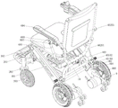
FIG. 1 is a perspective right-side view of the utility model;
FIG. 2 is a left side view of the structure of the present invention;
FIG. 3 is a right side view of the structure of the present invention;
FIG. 4 is a perspective front left view of the structure of the present invention;
FIG. 5 is a rear view of the structure of the present invention;
FIG. 6 is a perspective rear left view of the utility model;
FIG. 7 is a perspective view of the anti-tipping assembly of the present invention;
FIG. 8 is a perspective view of the structural locking assembly of the present invention;
fig. 9 is a perspective view of a portion of the structural locking assembly of the present invention.
In the figure: 1. a sideframe assembly; 101. a side plate; 102. a front plate; 103. a frame reinforcement tube; 2. a front wheel assembly; 201. a front wheel support plate; 202. a front wheel carrier; 203. moving the driving wheel forwards; 204. supporting the transverse pipe; 205. the support lug is pedaled; 3. a footrest assembly; 301. a pedal straight pipe; 302. a foot pedal; 4. a backrest assembly; 401. a lower support assembly; 40101. a rotating member; 40102. a lower support tube; 40103. lower folding ears; 40104. a lower support reinforcing tube; 402. an upper reclining assembly; 40201. a back tube; 40202. an upper folding ear; 40203. a backrest cushion; 40204. a handle tube; 403. a locking assembly; 40301. a locking seat; 40302. fixing the rod; 40303. a latch hook; 40304. a U-shaped hook; 40305. a switch cover; 5. a seat frame assembly; 501. a seat frame support plate; 502. a pedestal tube; 503. a cushion; 6. an armrest assembly; 601. a lower handrail tube; 602. an upper handrail tube; 603. a handrail folding member; 604. a handrail pad; 7. a manipulation component; 701. a fixed seat; 702. a telescopic rod; 703. a remote controller; 8. a rear wheel assembly; 801. a motor fixing plate; 802. Assembling a brushless motor; 803. a rear drive wheel; 9. a rollover prevention assembly; 901. an adjusting tube; 902. a wheel tube; 903. anti-overturning wheels; 10. a battery assembly; 1001. supporting the square pipe; 1002. a battery card board; 1003. assembling the battery; 11. and a control box.
Detailed Description
The technical solutions in the embodiments of the present invention will be described clearly and completely with reference to the accompanying drawings in the embodiments of the present invention, and it is obvious that the described embodiments are only some embodiments of the present invention, not all embodiments. Based on the embodiments in the present invention, all other embodiments obtained by a person skilled in the art without creative work belong to the protection scope of the present invention.
Examples
Referring to fig. 1, the present invention provides the following technical solutions: a foldable electric wheelchair comprises a side frame assembly 1, a front wheel assembly 2, a pedal assembly 3, a backrest assembly 4, a seat frame assembly 5, an armrest assembly 6, a control assembly 7, a rear wheel assembly 8, an anti-overturning assembly 9, a battery assembly 10 and a control box 11, wherein the backrest assembly 4 consists of a lower support assembly 401, an upper leaning assembly 402 and a locking assembly 403.
The inner side of one end of the side frame assembly 1 is hinged with the front wheel assembly 2 and the seat frame assembly 5.
The front wheel assembly 2 is hinged with the pedal assembly 3.
The inner side of the other end of the side frame assembly 1 is hinged to the lower support assembly 401 and bolted to the rear wheel assembly 8.
The top of the lower support assembly 401 and the bottom of the upper rest assembly 402 are hinged and detachably secured by a locking assembly 403.
A locking assembly 403 is secured to the top of the lower support assembly 401.
The mounting assembly 5 is hingedly connected to the upper recliner assembly 402.
The armrest assembly 6 is hingedly connected to the mounting assembly 5 and the upper recliner assembly 402.
The operation and control assembly 7 is detachably fixed on the armrest assembly 6.
The rear wheel assembly 8 is fixed to the rear side of the side frame assembly 1.
The anti-overturn component 9 is detachably fixed on the rear wheel component 8.
The front and rear surfaces of the battery assembly 10 are hinged to the front wheel assembly 2 and the lower support assembly 401, respectively.
The control box 11 is fixed to the lower support assembly 401.
The control assembly 7, the rear wheel assembly 8, the battery assembly 10 and the control box 11 are electrically connected.
In the embodiment, the side frame component 1 provides a structural foundation for the utility model, and the components are connected with each other to form a foundation frame of the utility model; the front wheel component 2 and the rear wheel component 8 are matched to drive the utility model to move, wherein the rear wheel component 8 provides driving force for the movement of the utility model; the foot pedal assembly 3 is used for placing the feet of a user; the backrest assembly 4 is divided into three parts, namely a lower support assembly 401, an upper leaning assembly 402 and a locking assembly 403, wherein the lower support assembly 401 plays a role in basic support connection and is hinged with the side frame assembly 1, so that the lower support assembly can rotate relative to the side frame assembly 1, and meanwhile, the lower support assembly and the upper leaning assembly 402 are also connected in a hinged mode and also rotate, but the locking assembly 403 can lock and fix the lower support assembly 401 and the upper leaning assembly 402, so that the stability of the structure of the utility model is ensured, wherein the upper leaning assembly 402 plays a backrest function and can provide leaning for a user; the seating support assembly 5 provides a seated position for the user, wherein the seating support assembly 5 is hinged to both the upper recliner assembly 402 and the armrest assembly 6; the control component 7 is used for operating the movement of the utility model; the anti-tipping component 9 is used for ensuring that the utility model cannot tip over after being folded vertically; the battery assembly 10 is used for providing power for the driving of the present invention, and the control box 11 is present for ensuring the smooth completion of the control operation of the present invention.
Referring to fig. 2-6, the side frame assembly 1 includes two side plates 101, a front plate 102 bolted to the inner sides of one end of the two side plates 101, and a frame reinforcement pipe 103 bolted to the side opposite to the two side plates 101.
In this embodiment, two curb plates 101 are the basis, link together two curb plates 101 through frame reinforcing pipe 103, have improved the utility model discloses a structural strength of automobile body, the existence of two front bezel 102 does the utility model discloses the installation of basic part provides the position, and wherein the inboard of curb plate 101 indicates the relative one side of two curb plates 101 to under unfolded state, two curb plates 101 are the slope setting of below backward, and two curb plates 101 are once only pour the shaping by almag, and structural strength is high.
Referring to fig. 2, 3, 4 and 6, the front wheel assembly 2 includes two front wheel supporting plates 201, the two front wheel supporting plates 201 are respectively hinged to the inner sides of the corresponding front plates 102, the bottoms of the two front wheel supporting plates 201 are respectively and rotatably connected with front wheel supports 202, the interiors of the two front wheel supports 202 are respectively and rotatably connected with front moving wheels 203, a supporting transverse tube 204 is connected between the opposite sides of the two front wheel supports 202 through bolts, and two pedal lugs 205 are welded on the outer surface of the supporting transverse tube 204.
In this embodiment, two front wheel backup pads 201 can take place to rotate foldingly for two front bezel 102, have formed a beta structure, and wherein antedisplacement driving wheel 203 can take place to roll subaerial, and antedisplacement driving wheel 203 can take place rotatory the rotation for taking place with front wheel backup pad 201, has played the effect of redirecting, and the existence of supporting horizontal pipe 204 has two effects, and one can strengthen and improve the utility model discloses a holistic support intensity, one is for pedal subassembly 3 provides the fixed position of installation, and wherein front wheel backup pad 201 is once only pour the shaping by almag.
Referring to fig. 2-4, the pedal assembly 3 includes two pedal straight pipes 301, one end of each of the two pedal straight pipes 301 is hinged to each of the two pedal lugs 205, and the other end of each of the two pedal straight pipes 301 is fixedly mounted with a pedal plate 302.
In this embodiment, two pedal straight tubes 301 and a running-board 302 constitute a fixed whole, and two pedal straight tubes 301 can take place to rotate for two pedal journal stirrup 205, and wherein normal state two pedal straight tube 301's one end is contradicted and is being supported the surface of violently managing 204's below, and when user's both feet were placed on running-board 302, can drive two pedal straight tubes 301 and upwards rotate, nevertheless because the existence of violently managing 204 of support, can play spacing blocking effect, thereby guaranteed the utility model discloses structural design's rationality.
Referring to fig. 2-6, 8 and 9, the lower support assembly 401 includes two rotating members 40101, the two rotating members 40101 are respectively rotatably connected to the inner sides of the two side plates 101, lower support tubes 40102 are fixedly mounted on the outer surfaces of the two rotating members 40101, the lower support tubes 40102 are U-shaped, two lower folding lugs 40103 are welded to the top of the lower support tubes 40102, and lower support reinforcing tubes 40104 are welded to the inner sides of the lower support tubes 40102;
the upper leaning assembly 402 comprises a backrest tube 40201, two upper folding ears 40202 are welded at the bottom of the backrest tube 40201, each upper folding ear 40202 is hinged with two lower folding ears 40103, a backrest pad 40203 is fixedly mounted on the front surface of the backrest tube 40201, and a handle tube 40204 is connected to the top of the backrest tube 40201 through a bolt;
locking assembly 403 includes locking seat 40301, and the bolted connection of locking seat 40301 is at the top of lower support tube 40102, and the inside rotation of locking seat 40301 is connected with dead lever 40302, and the outer surface fixed mounting of dead lever 40302 has two latch hooks 40303, and the inside sliding connection of locking seat 40301 has U type couple 40304, and back pipe 40201 is all run through at the both ends of U type couple 40304, and the pot head of two latch hooks 40303 is equipped with switch cover 40305.
In this embodiment, the lower support tube 40102 and the two rotating members 40101 form a whole, so that the lower support tube 40102 can be folded and rotated relative to the two side plates 101, the lower support tube 40102 and the backrest tube 40201 are directly hinged by the lower folding lug 40103 and the upper folding lug 40202 and locked by the U-shaped hook 40304 in the locking assembly 403, and the structural firmness between the lower support tube 40102 and the backrest tube 40201 is ensured in a normal state.
Referring to fig. 2, 3, 4 and 6, the seat frame assembly 5 includes two seat frame support plates 501, the two seat frame support plates 501 are respectively hinged to the two front plates 102, seat frame pipes 502 are welded to the outer sides of the two seat frame support plates 501, the seat frame pipes 502 are U-shaped, two ends of the seat frame pipes 502 are hinged to two sides of the backrest pipe 40201, and a seat cushion 503 is fixedly installed on the top of the seat frame pipes 502.
In this embodiment, the cooperation of the two seat frame support plates 501 and the one seat frame tube 502 can ensure the stability of the seat frame assembly 5 while being foldable, and the positions of the side plate 101 and the backrest tube 40201 are not changed, so the structure of the seat frame assembly 5 can be kept stable, and the seat cushion 503 provides a sitting position for the user.
Referring to fig. 2, 3, 4 and 6, the armrest assembly 6 includes two lower armrest tubes 601 and two upper armrest tubes 602, one end of each of the two lower armrest tubes 601 is hinged to two sides of the seat frame tube 502, the other end of each of the two lower armrest tubes 601 is hinged to an armrest folding member 603, one end of each of the two upper armrest tubes 602 is hinged to two sides of the backrest tube 40201, the other end of each of the two upper armrest tubes 602 is hinged to a corresponding armrest folding member 603, and an armrest pad 604 is fixedly mounted on the top of each of the two upper armrest tubes 602.
In this embodiment, two armrest assemblies 6 provide a place for placing the user's hands, and the user can directly place the user's hands on the two armrest pads 604.
Specifically, the control assembly 7 comprises a fixed seat 701, the fixed seat 701 is fixed at the bottom of one of the upper handrail tubes 602 through a bolt, an expansion link 702 is detachably fixed in the fixed seat 701, and one end of the expansion link 702 is connected with a remote controller 703 through a bolt.
In this embodiment, wherein the operating assembly 7 is all fixed on the handrail assembly 6 on the right under the normal condition, because the operating assembly 7 is detachable structure, consequently, can dismantle and install on the left side, can be applicable to the operator of the different habits of right hand and left hand, telescopic link 702 indicates that telescopic link 702 is located the length of fixing base 701 and can adjust simultaneously, threaded passage has been seted up to the bottom of fixing base 701, when the length adjustment of telescopic link 702 is fit for the position, even the user feels convenient operation's position, through the plum blossom rotation in threaded passage internal rotation, the surface that finally can conflict telescopic link 702 is fixed with its centre gripping, thereby fix the position of remote controller 703, carry out corresponding operation through remote controller 703.
Referring to fig. 2-6, the rear wheel assembly 8 includes two motor fixing plates 801, the two motor fixing plates 801 are respectively bolted to the rear end portions of the two side plates 101, brushless motor assemblies 802 are fixedly mounted on the inner sides of the two motor fixing plates 801, and rear driving wheels 803 are fixedly mounted on the output shafts of the two brushless motor assemblies 802.
In this embodiment, drive two back drive wheels 803 through two brushless motor assemblies 802 and roll subaerial, can drive the utility model discloses remove, remove easy operation.
Referring to fig. 2 to 7, the anti-tip assembly 9 includes two adjusting tubes 901, wheel tubes 902 are inserted into the two adjusting tubes 901, each adjusting tube 901 and each wheel tube 902 are fixedly connected to a corresponding motor fixing plate 801 by bolts, and anti-tip wheels 903 are disposed on the two wheel tubes 902.
In this embodiment, wherein the length that wheel pipe 902 is located regulating tube 901 can be adjusted, but the wheel pipe 902 after the regulation and the hole of regulating tube 901 must the one-to-one to adopt the bolt to fix wheel pipe 902 and regulating tube 901 jointly with curb plate 101, accomplished the fixed of preventing turning over subassembly 9, wherein work as the utility model discloses after folding vertical, rely on preventing turning over wheel 903 and ground contact, thereby played the effect of preventing toppling over.
Referring to fig. 2-5, the battery assembly 10 includes two square supporting tubes 1001, two ends of each square supporting tube 1001 are respectively hinged to the horizontal supporting tube 204 and the lower reinforcing tube 40104, the inner sides of the two square supporting tubes 1001 are respectively connected with a battery clamping plate 1002 through bolts, and a battery assembly 1003 is connected between the two opposite sides of the two battery clamping plates 1002 through bolts.
In this embodiment, do through battery assembly 1003 the utility model discloses a power equipment provides electric power as power, thereby ensures the utility model discloses electric wheelchair can normal use, and the existence of two same support side's pipe 1001 is in order to guarantee that battery pack 10 can accomplish folding operation smoothly.
Referring to fig. 1, 5 and 6, the remote control 703, the two brushless motors assemblies 802, the battery assembly 1003 and the control box 11 are electrically connected.
In this embodiment, the remote controller 703, the two brushless motors assemblies 802, the battery assembly 1003 and the control box 11 are mutually matched to ensure that the electric wheelchair can be normally used.
A method of folding a foldable electric wheelchair comprising the steps of:
one) the switch sleeve 40305 is dialed downwards to drive the two latch hooks 40303 to rotate, at this time, the fixing rod 40302 rotates, the two latch hooks 40303 drive the U-shaped hook 40304 to slide downwards, and the U-shaped hook 40304 comes out of the inner part of the backrest tube 40201 and enters the inner part of the locking seat 40301;
secondly), the lower support tube 40102 is pulled to rotate backwards, and the lower support tube 40102 rotates relative to the two side plates 101 through the two rotating pieces 40101;
thirdly) when the second step is carried out, the backrest tube 40201 is inclined forwards and rotates, the seat tube 502 rotates downwards, the two lower handrail tubes 601 rotate along with the seat tube 502 and rotate towards the direction close to the seat tube 502, the two upper handrail tubes 602 rotate in the same direction as the backrest tube 40201, the two side plates 101 rotate forwards and downwards, the two front wheel support plates 201 rotate towards the upper right, the two support square tubes 1001 move horizontally and backwards, and the two pedal straight tubes 301 rotate towards the upper back;
fourthly) when the back cushion 40203 contacts with the cushion 503, the back cushion 40203 is pressed and pressed, then the pedal plate 302 is pulled to rotate in the direction close to the seat frame pipe 502, and the two front wheel support plates 201 are folded and parallel to the two side plates 101;
fifthly), the handle tube 40204 and the pedal plate 302 are held by hands to be lifted vertically, so that the two anti-overturning wheels 903 are in contact with the ground.
Finally, it should be noted that: although the present invention has been described in detail with reference to the foregoing embodiments, it will be apparent to those skilled in the art that modifications may be made to the embodiments described in the foregoing embodiments, or equivalents may be substituted for elements thereof. Any modification, equivalent replacement, or improvement made within the spirit and principle of the present invention should be included in the protection scope of the present invention.
Claims (12)
1. The utility model provides a collapsible electronic wheelchair, includes side bearer subassembly (1), front wheel subassembly (2), pedal subassembly (3), back subassembly (4), seat frame subassembly (5), handrail subassembly (6), controls subassembly (7), rear wheel subassembly (8), prevents turning over subassembly (9), battery pack (10), control box (11), back subassembly (4) comprise lower support subassembly (401), upper leaning on subassembly (402) and locking Assembly (403), its characterized in that:
the inner side of one end of the side frame component (1) is hinged with the front wheel component (2) and the seat frame component (5);
the front wheel assembly (2) is hinged with the pedal assembly (3);
the inner side of the other end of the side frame assembly (1) is hinged with the lower support assembly (401) and is connected with the rear wheel assembly (8) through a bolt;
the top of the lower support assembly (401) and the bottom of the upper leaning assembly (402) are hinged and detachably fixed through a locking assembly (403);
the locking assembly (403) is fixed on the top of the lower support assembly (401);
the seat frame assembly (5) is hinged with the upper leaning assembly (402);
the armrest component (6) is hinged with the seat frame component (5) and the upper leaning component (402);
the control component (7) is detachably fixed on the handrail component (6);
the rear wheel assembly (8) is fixed at the rear side of the side frame assembly (1);
the anti-overturning assembly (9) is detachably fixed on the rear wheel assembly (8);
the front surface and the back surface of the battery component (10) are respectively hinged with the front wheel component (2) and the lower support component (401);
the control box (11) is fixed on the lower support assembly (401);
the control assembly (7), the rear wheel assembly (8), the battery assembly (10) and the control box (11) are electrically connected.
2. The foldable electric wheelchair as claimed in claim 1, wherein: the side frame assembly (1) comprises two side plates (101), the inner sides of one ends of the two side plates (101) are connected with a front plate (102) through bolts, and a frame reinforcing pipe (103) is connected between the opposite sides of the two side plates (101) through bolts.
3. The foldable electric wheelchair as claimed in claim 2, wherein: front wheel subassembly (2) are including two front wheel backup pads (201), two front wheel backup pad (201) is articulated with the inboard of corresponding front bezel (102) respectively, two the bottom of front wheel backup pad (201) is all rotated and is connected with front wheel support (202), two the inside of front wheel support (202) is all rotated and is connected with antedisplacement driving wheel (203), two bolted connection has between the relative one side of front wheel support (202) and supports violently pipe (204), the skin weld who supports violently pipe (204) has two pedal journal stirrup (205).
4. A foldable electric wheelchair in accordance with claim 3, wherein: the pedal assembly (3) comprises two pedal straight pipes (301), one ends of the two pedal straight pipes (301) are hinged to the two pedal support lugs (205) respectively, and pedals (302) are fixedly mounted at the other ends of the two pedal straight pipes (301).
5. The foldable electric wheelchair as claimed in claim 2, wherein: the lower support assembly (401) comprises two rotating parts (40101), the two rotating parts (40101) are respectively connected with the inner sides of two side plates (101) in a rotating mode, lower support tubes (40102) are fixedly installed on the outer surfaces of the two rotating parts (40101), the lower support tubes (40102) are U-shaped, two lower folding lugs (40103) are welded to the tops of the lower support tubes (40102), and lower support reinforcing tubes (40104) are welded to the inner sides of the lower support tubes (40102);
the upper leaning assembly (402) comprises a backrest pipe (40201), two upper folding lugs (40202) are welded at the bottom of the backrest pipe (40201), each upper folding lug (40202) is hinged with two lower folding lugs (40103) respectively, a backrest pad (40203) is fixedly installed on the front surface of the backrest pipe (40201), and a handle pipe (40204) is connected to the top of the backrest pipe (40201) through a bolt;
locking subassembly (403) are including locking seat (40301), the bolted connection of locking seat (40301) is at the top of lower supporting pipe (40102), the inside rotation of locking seat (40301) is connected with dead lever (40302), the external fixed surface of dead lever (40302) installs two latch hooks (40303), the inside sliding connection of locking seat (40301) has U type couple (40304), back pipe (40201), two all run through at the both ends of U type couple (40304) the pot head of latch hook (40303) is equipped with switch cover (40305).
6. The foldable electric wheelchair as claimed in claim 5, wherein: seat frame subassembly (5) include two seat frame backup pads (501), two seat frame backup pad (501) are articulated with two front bezel (102) respectively, two the outside welding of seat frame backup pad (501) has seat pipe (502), seat pipe (502) are the U type, the both ends of seat pipe (502) are articulated with the both sides of back pipe (40201), the top fixed mounting of seat pipe (502) has cushion (503).
7. The foldable electric wheelchair as claimed in claim 6, wherein: handrail subassembly (6) include two down handrail pipe (601) and go up handrail pipe (602), two the one end of handrail pipe (601) is articulated with the both sides of seat pipe (502) respectively down, two the other end of handrail pipe (601) all articulates down has handrail folded piece (603), two go up the one end of handrail pipe (602) and articulate with the both sides of back pipe (40201) respectively, two go up the other end of handrail pipe (602) and articulate with corresponding handrail folded piece (603) respectively, two go up the equal fixed mounting in top of handrail pipe (602) and have handrail pad (604).
8. The foldable electric wheelchair as claimed in claim 7, wherein: control subassembly (7) including fixing base (701), fixing base (701) pass through the bolt fastening in the bottom of one of them handrail pipe (602), the inside of fixing base (701) can be dismantled and be fixed with telescopic link (702), the one end bolted connection of telescopic link (702) has remote controller (703).
9. The foldable electric wheelchair as claimed in claim 2, wherein: rear wheel subassembly (8) include two motor fixed plate (801), two motor fixed plate (801) bolted connection respectively is in the rear end portion of two curb plates (101), two the equal fixed mounting in inboard of motor fixed plate (801) has brushless motor assembly (802), two the equal fixed mounting of output shaft of brushless motor assembly (802) has back drive wheel (803).
10. The foldable electric wheelchair as claimed in claim 9, wherein: the anti-overturning assembly (9) comprises two adjusting pipes (901), wheel pipes (902) are arranged inside the two adjusting pipes (901) in an inserting mode, each adjusting pipe (901) and each wheel pipe (902) are fixedly connected with a corresponding motor fixing plate (801) through bolts, and anti-overturning wheels (903) are arranged on the two wheel pipes (902).
11. The foldable electric wheelchair as claimed in claim 5, wherein: battery pack (10) are including two support side's pipe (1001), two the both ends of support side's pipe (1001) are equallyd divide and are do not violently managed (204) and lower support reinforced pipe (40104) articulated with the support, two the equal bolted connection in inboard of support side's pipe (1001) has battery cardboard (1002), two bolted connection has battery assembly (1003) between the relative one side of battery cardboard (1002).
12. The foldable electric wheelchair as claimed in claim 8, wherein: the remote controller (703), the two brushless motor assemblies (802), the battery assembly (1003) and the control box (11) are electrically combined.
Priority Applications (1)
| Application Number | Priority Date | Filing Date | Title |
|---|---|---|---|
| CN201921609086.2U CN211271759U (en) | 2019-09-25 | 2019-09-25 | Foldable electric wheelchair |
Applications Claiming Priority (1)
| Application Number | Priority Date | Filing Date | Title |
|---|---|---|---|
| CN201921609086.2U CN211271759U (en) | 2019-09-25 | 2019-09-25 | Foldable electric wheelchair |
Publications (1)
| Publication Number | Publication Date |
|---|---|
| CN211271759U true CN211271759U (en) | 2020-08-18 |
Family
ID=72029373
Family Applications (1)
| Application Number | Title | Priority Date | Filing Date |
|---|---|---|---|
| CN201921609086.2U Active CN211271759U (en) | 2019-09-25 | 2019-09-25 | Foldable electric wheelchair |
Country Status (1)
| Country | Link |
|---|---|
| CN (1) | CN211271759U (en) |
Cited By (2)
| Publication number | Priority date | Publication date | Assignee | Title |
|---|---|---|---|---|
| CN116549229A (en) * | 2022-01-28 | 2023-08-08 | 康扬股份有限公司 | Anti-strut structure |
| CN118402915A (en) * | 2024-05-20 | 2024-07-30 | 苏州凯道智能设备有限公司 | A foldable electric wheelchair |
-
2019
- 2019-09-25 CN CN201921609086.2U patent/CN211271759U/en active Active
Cited By (2)
| Publication number | Priority date | Publication date | Assignee | Title |
|---|---|---|---|---|
| CN116549229A (en) * | 2022-01-28 | 2023-08-08 | 康扬股份有限公司 | Anti-strut structure |
| CN118402915A (en) * | 2024-05-20 | 2024-07-30 | 苏州凯道智能设备有限公司 | A foldable electric wheelchair |
Similar Documents
| Publication | Publication Date | Title |
|---|---|---|
| CN110934696A (en) | Foldable electric wheelchair and folding method thereof | |
| EP0145278B1 (en) | Wheelchair | |
| US7451848B2 (en) | Foldable personal mobility vehicle | |
| US8186695B2 (en) | Comfort wheelchair | |
| US4786072A (en) | Collapsible wheelchair and lift assembly | |
| CN113730116B (en) | Foldable wheelchair | |
| CN209933243U (en) | Auxiliary standing wheelchair with front wheel base and rear wheel base variable | |
| CN212816827U (en) | Novel electric folding wheelchair | |
| CN116849939A (en) | Foldable wheelchair | |
| KR20220030058A (en) | Bed wheelchair for patient transfer | |
| CA2368810C (en) | Folding wheelchair with a positioning assembly | |
| WO2021208589A1 (en) | Foldable wheelchair | |
| CN117731493A (en) | A foldable wheelchair | |
| CN209172729U (en) | A kind of wheelchair to folding backrest | |
| CN114767408A (en) | Intelligent electric folding wheelchair | |
| KR102359574B1 (en) | Wheelchair with lifting function | |
| CN211382257U (en) | an electric wheelchair | |
| CN217548411U (en) | Intelligent electric folding wheelchair | |
| EP1590202A2 (en) | Powered vehicle for personal transport | |
| CN209916423U (en) | Wheel chair | |
| CN212395233U (en) | Combined electric shifting transfer wheelchair | |
| CN112319682B (en) | An automatic foldable electric walker and using method | |
| CN111759599B (en) | Combined electric displacement transfer wheelchair | |
| CN219782994U (en) | Foot support device of electric wheelchair | |
| KR200381749Y1 (en) | Separatable electric motor for wheelchair |
Legal Events
| Date | Code | Title | Description |
|---|---|---|---|
| GR01 | Patent grant | ||
| GR01 | Patent grant |