CN211265430U - A wafer pick-and-place device for wafer sorting - Google Patents
A wafer pick-and-place device for wafer sorting Download PDFInfo
- Publication number
- CN211265430U CN211265430U CN202021357670.6U CN202021357670U CN211265430U CN 211265430 U CN211265430 U CN 211265430U CN 202021357670 U CN202021357670 U CN 202021357670U CN 211265430 U CN211265430 U CN 211265430U
- Authority
- CN
- China
- Prior art keywords
- wafer
- sorting
- mounting
- sliding
- driving
- Prior art date
- Legal status (The legal status is an assumption and is not a legal conclusion. Google has not performed a legal analysis and makes no representation as to the accuracy of the status listed.)
- Active
Links
Images




Landscapes
- Container, Conveyance, Adherence, Positioning, Of Wafer (AREA)
Abstract
Description
技术领域technical field
本实用新型涉及晶圆生产设备技术领域,尤其涉及一种晶圆分选用料片取放装置。The utility model relates to the technical field of wafer production equipment, in particular to a material pick-and-place device for wafer sorting.
背景技术Background technique
晶圆是指制作硅半导体积体电路所用的硅晶片,由于其形状为圆形,故称为晶圆。晶圆加工过程中,由于外界因素会导致生产的晶圆种类和质量有所不同,通常在自动光学检测机中进行AOI测试,对晶圆的种类、质量进行检测后,然后依据种类及质量的不同对晶圆进行分选,把不同的晶圆分隔开来。Wafer refers to the silicon wafer used to make silicon semiconductor integrated circuits. Because of its circular shape, it is called a wafer. In the process of wafer processing, due to external factors, the type and quality of the produced wafers will be different. Usually, AOI test is carried out in an automatic optical inspection machine. The wafers are sorted differently to separate the different wafers.
目前,晶圆的分选工艺主要是通过人工进行分选,分选工人需要对每片晶圆进行仔细检查后进行归类放置,不但分选效率低,劳动强度大,分选成本高,且人工分选无法对衬底号进行排序,在分选过程中,由于人员操作不细心等各种主观原因易导致分选错误,且在分选时易对晶圆造成划伤,会导致晶圆直接报废或降级处理,直接影响晶圆的生产质量及产品合格率。因此,开发一种晶圆分选用料片取放装置,不但具有迫切的研究价值,也具有良好的经济效益和工业应用潜力,这正是本实用新型得以完成的动力所在和基础。At present, the sorting process of wafers is mainly carried out manually. The sorting workers need to carefully check each wafer before classifying and placing them, which not only has low sorting efficiency, high labor intensity, high sorting cost, and Manual sorting cannot sort the substrate numbers. During the sorting process, due to various subjective reasons such as inattentive operation by personnel, sorting errors are likely to be caused, and the wafers are easily scratched during sorting, which will cause the wafers to be damaged. Direct scrapping or downgrading will directly affect the production quality and product qualification rate of wafers. Therefore, the development of a wafer pick-and-place device for wafer sorting not only has urgent research value, but also has good economic benefits and industrial application potential, which is the driving force and foundation of the present invention.
发明内容SUMMARY OF THE INVENTION
为了克服上述所指出的现有技术的缺陷,本发明人对此进行了深入研究,在付出了大量创造性劳动后,从而完成了本实用新型。In order to overcome the above-mentioned defects of the prior art, the present inventor has conducted in-depth research on this, and has completed the present utility model after a lot of creative work.
具体而言,本实用新型所要解决的技术问题是:提供一种晶圆分选用料片取放装置,以解决目前人工进行晶圆分选存在的分选效率低、无法对衬底号排序、易分选错误及划伤晶圆的技术问题。Specifically, the technical problem to be solved by the present utility model is: to provide a material pick-and-place device for wafer sorting, so as to solve the problems of low sorting efficiency, inability to sort substrate numbers, Technical issues that are prone to sorting errors and scratched wafers.
为解决上述技术问题,本实用新型的技术方案是:For solving the above-mentioned technical problems, the technical scheme of the present utility model is:
一种晶圆分选用料片取放装置,包括安装架,所述安装架上沿X轴方向滑动安装有第一驱动装置驱动的安装板,所述安装板上设有由第二驱动装置驱动、且沿Z轴方向滑动的安装座,所述安装座上沿Y轴方向滑动安装有第三驱动装置驱动的托板,所述托板末端具有一晶圆托放部,所述晶圆托放部的上表面开设有吸片孔,所述托板内部开设有与所述吸片孔相连通的气道。A material pick-and-place device for wafer sorting, comprising a mounting frame on which a mounting plate driven by a first driving device is slidably mounted along the X-axis direction, and a mounting plate driven by a second driving device is installed on the mounting plate , and a mounting seat that slides along the Z-axis direction, the mounting seat is slidably installed along the Y-axis direction with a support plate driven by a third drive device, and the end of the support plate has a wafer holding part, the wafer support A suction sheet hole is opened on the upper surface of the placing portion, and an air passage communicated with the suction sheet hole is opened inside the support plate.
作为一种改进的技术方案,所述安装架上沿水平方向设有两平行设置的第一滑轨,所述第一滑轨上滑动安装有第一滑块,所述第一滑块与所述安装板固定连接,所述安装板通过所述第一滑轨、所述第一滑块滑动安装于所述安装架上;As an improved technical solution, the mounting frame is provided with two first sliding rails arranged in parallel along the horizontal direction, and a first sliding block is slidably installed on the first sliding rail, and the first sliding block is connected to the first sliding block. the mounting plate is fixedly connected, and the mounting plate is slidably mounted on the mounting frame through the first sliding rail and the first sliding block;
所述第一驱动装置包括固定安装于所述安装架上的驱动电机,所述安装架的一端转动安装有与所述驱动电机输出轴传动连接的主动带轮,所述安装架的另一端转动安装有与所述主动带轮对应设置的从动带轮,所述从动带轮与所述主动带轮间架绕有传动带,且所述从动带轮与所述主动带轮通过所述传动带传动连接,所述安装板与所述传动带的一侧固定连接。The first drive device includes a drive motor fixedly mounted on the mounting frame, one end of the mounting frame is rotatably mounted with a driving pulley connected to the output shaft of the drive motor, and the other end of the mounting frame rotates A driven pulley corresponding to the driving pulley is installed, a transmission belt is wound between the driven pulley and the driving pulley, and the driven pulley and the driving pulley pass through the transmission belt In the transmission connection, the mounting plate is fixedly connected with one side of the transmission belt.
作为一种改进的技术方案,所述第二驱动装置包括电缸,所述电缸竖直固定安装于所述安装板上,所述安装座与所述电缸的滑板固定连接。As an improved technical solution, the second driving device includes an electric cylinder, the electric cylinder is vertically and fixedly installed on the mounting plate, and the mounting seat is fixedly connected with the sliding plate of the electric cylinder.
作为一种改进的技术方案,所述托板设有两个,所述安装座上设有两平行设置的第二滑轨,所述第二滑轨上分别滑动安装有第二滑块,两所述托板分别固定安装于所述第二滑块上,且两所述托板上下设置,两所述托板的晶圆托放部于竖直方向上对应设置;As an improved technical solution, there are two supporting plates, two parallel second sliding rails are arranged on the mounting base, and second sliding blocks are slidably installed on the second sliding rails, respectively. The supporting plates are respectively fixed and installed on the second sliding block, and the two supporting plates are arranged up and down, and the wafer holding parts of the two supporting plates are correspondingly arranged in the vertical direction;
所述第三驱动装置设有两套,两所述第三驱动装置分别于所述安装座的两侧安装,且分别与所述第二滑块驱动相连。The third driving device is provided with two sets, and the two third driving devices are respectively installed on both sides of the mounting seat and are respectively drivingly connected with the second sliding block.
作为一种改进的技术方案,所述第三驱动装置包括固定安装于所述安装座上的磁耦合式无杆气缸,所述磁耦合式无杆气缸的滑动磁体固定安装有连接块,所述连接块朝向所述第二滑块的一侧安装有凸轮轴承随动器,所述第二滑块上开设有与所述凸轮轴承随动器相适配的卡槽,所述凸轮轴承随动器卡装于所述卡槽内。As an improved technical solution, the third driving device includes a magnetically coupled rodless cylinder fixedly mounted on the mounting seat, and a connecting block is fixedly mounted on the sliding magnet of the magnetically coupled rodless cylinder, and the A cam bearing follower is installed on the side of the connecting block facing the second slider, the second slider is provided with a slot matching the cam bearing follower, and the cam bearing follows The device is clamped in the slot.
作为一种改进的技术方案,所述安装座的两侧端部均对应安装有液压缓冲器,所述连接块分别于对应设置的两所述液压缓冲器间设置。As an improved technical solution, hydraulic buffers are correspondingly installed on both ends of the mounting seat, and the connecting blocks are respectively arranged between the two correspondingly arranged hydraulic buffers.
作为一种改进的技术方案,所述晶圆托放部的上表面开设有吸片槽,所述吸片槽与所述吸片孔相接。As an improved technical solution, a suction groove is formed on the upper surface of the wafer holding part, and the suction groove is connected with the suction hole.
作为一种改进的技术方案,所述所述晶圆托放部的端部为圆弧状,所述吸片孔位于所述吸片槽的中间位置。As an improved technical solution, the end of the wafer holding portion is arc-shaped, and the suction hole is located in the middle of the suction groove.
作为一种改进的技术方案,所述安装座上还设有用以检测花篮中晶圆放料情况的传感器,所述传感器固定安装于所述安装座远离所述安装板的一端底部。As an improved technical solution, the mounting seat is further provided with a sensor for detecting the unloading condition of the wafers in the flower basket, and the sensor is fixedly mounted on the bottom of one end of the mounting seat away from the mounting plate.
作为一种进一步改进的技术方案,所述传感器为数字激光传感器。As a further improved technical solution, the sensor is a digital laser sensor.
作为一种改进的技术方案,所述安装架上固定安装有包覆所述第一驱动装置的防护板,所述安装座上固定安装有包覆所述第三驱动装置和所述托板的防护壳。As an improved technical solution, a protective plate covering the first driving device is fixedly installed on the installation frame, and a protective plate covering the third driving device and the supporting plate is fixedly installed on the installation seat. protective case.
采用了上述技术方案后,本实用新型的有益效果是:After adopting the above-mentioned technical scheme, the beneficial effects of the present utility model are:
(1)设有的该晶圆分选用料片取放装置,通过控制驱动电机、电缸和磁耦合式无杆气缸配合动作,实现托板的精确位移,通过托板末端的晶圆托放部实现对晶圆的取放,且晶圆托放部开设的吸片孔,能够实现对晶圆背面的有效吸附,在对晶圆取放过程中,不会发生晶圆的掉落或位置偏移,为晶圆的准确放置提供了可靠保障;使用时,在分选机上并排放置待分选花篮和归类放置花篮,待分选花篮内放有需要分选的晶圆料片,归类放置花篮为空花篮,分别用以放置同一种类、质量的晶圆,在分选机分选指令控制下,托板精确运动,将待分选花篮内的晶圆料片取出并分别精确放置到相应的归类放置花篮内,完成对晶圆的归类分选。相较传统的人工分选方式,不但分选效率大大提高,降低了分选成本,有效避免了分选错误的发生,且在分选过程中,通过托板取放晶圆,不会对晶圆造成划伤,确保了晶圆质量不受影响,在实现晶圆归类分选的同时,能够对分选晶圆的衬底号进行排序放置,方便实用。(1) The wafer picking and placing device for the wafer sorting is provided, and the precise displacement of the pallet is realized by controlling the coordinated action of the driving motor, the electric cylinder and the magnetically coupled rodless air cylinder, and the wafer is placed through the wafer at the end of the pallet. The wafer holding part realizes the pick and place of the wafer, and the suction hole opened in the wafer holding part can realize the effective adsorption of the back of the wafer. During the process of picking and placing the wafer, the drop or position of the wafer will not occur. The offset provides a reliable guarantee for the accurate placement of the wafers; when in use, place the flower baskets to be sorted and the flower baskets sorted side by side on the sorting machine. The similar placement flower baskets are empty flower baskets, which are used to place wafers of the same type and quality. Under the control of the sorting instructions of the sorting machine, the pallet moves accurately, and the wafer blanks in the flower baskets to be sorted are taken out and placed accurately respectively. To the corresponding classification and placement flower baskets, the classification and sorting of the wafers are completed. Compared with the traditional manual sorting method, not only the sorting efficiency is greatly improved, the sorting cost is reduced, and the occurrence of sorting errors is effectively avoided. The scratches are caused to ensure that the quality of the wafers is not affected. While the wafers are sorted and sorted, the substrate numbers of the sorted wafers can be sorted and placed, which is convenient and practical.
(2)通过电缸实现对安装座的滑动驱动,精度高,且更环保、干净,在保证刚性的同时,有效减少了气缸润滑油脂对无尘环境的污染。(2) The sliding drive of the mounting seat is realized by the electric cylinder, which has high precision, and is more environmentally friendly and clean. While ensuring rigidity, it effectively reduces the pollution of the cylinder lubricating oil to the dust-free environment.
(3)托板上下设有两个,且分别通过磁耦合式无杆气缸驱动,一次可取放两个晶圆,从而有效提高了该装置的分选效率。(3) There are two upper and lower pallets, and they are driven by magnetically coupled rodless cylinders, so that two wafers can be taken and placed at a time, thereby effectively improving the sorting efficiency of the device.
(4)磁耦合式无杆气缸的滑动磁体无动密封件、无外部泄露,满足晶圆分选的无尘需求,且磁耦合式无杆气缸整体安装尺寸小,轴向空间小,通过磁耦合式无杆气缸实现对托板的驱动,以及磁耦合式无杆气缸与第二滑轨上下结构设计、并通过连接块、凸轮轴承随动器连接,更加节省了安装空间,使得取放晶圆部分结构紧凑,占用空间小,为晶圆的灵活取放提供了便利,此外,通过凸轮轴承随动器及卡槽实现与第二滑块的连接,满足磁耦合式无杆气缸与第二滑轨间的安装精度需求,安装难度大大降低。(4) The sliding magnet of the magnetically coupled rodless cylinder has no moving seals and no external leakage, which meets the dust-free requirements of wafer sorting, and the overall installation size of the magnetically coupled rodless cylinder is small, and the axial space is small. The coupled rodless cylinder realizes the drive of the pallet, and the magnetic coupling rodless cylinder and the upper and lower structure design of the second slide rail are connected through the connecting block and the cam bearing follower, which saves the installation space and makes the picking and placing of crystals. The round part has a compact structure and takes up little space, which facilitates the flexible pick and place of wafers. In addition, the connection with the second slider is realized through the cam bearing follower and the slot, which meets the requirements of the magnetic coupling rodless cylinder and the second slider. The installation accuracy between the slide rails is required, and the installation difficulty is greatly reduced.
(5)磁耦合式无杆气缸行程两端设有的液压缓冲器,能够实现安全缓冲,降低滑动冲击,起保护作用,使得取放晶圆运行平稳,且能够确保取放料片时托板伸出长度一致,实现对晶圆的精准取放。(5) The hydraulic buffers provided at both ends of the stroke of the magnetically coupled rodless cylinder can realize safe buffering, reduce sliding impact, and play a protective role. The extension length is the same to achieve precise pick and place of wafers.
(6)晶圆托放部开设有的与吸片孔相接的吸片槽,增大了与晶圆间的吸合面积,使得晶圆在取放过程中吸合更牢固,满足了对晶圆高效率分选的需求。(6) The suction slot connected to the suction hole is provided in the wafer holding part, which increases the suction area between the wafer and the wafer, so that the wafer is more firmly sucked during the picking and placing process, which satisfies the requirement of The need for efficient wafer sorting.
(7)安装座端部安装有的传感器,能够在取放晶圆时对盛放晶圆的花篮进行检测,检测花篮内是否无料或料片是否放满,以便于操作人员对无料或料满的花篮进行更换。(7) The sensor installed at the end of the mounting seat can detect the flower basket containing the wafer when picking and placing the wafer, and detect whether there is no material in the flower basket or whether the material is full, so as to facilitate the operator to check whether there is no material or no material. Replace the full flower basket.
(8)安装架上固定安装有的防护板,实现对第一驱动装置的有效防护,且避免了第一驱动装置工作时对无尘分选环境的污染,安装座上固定安装有的防护壳,实现了对第三驱动装置和托板的有效防护,且进一步确保了无尘需求。(8) The protective plate is fixedly installed on the mounting frame, which can effectively protect the first driving device and avoid the pollution of the dust-free sorting environment when the first driving device is working. The protective shell is fixedly installed on the mounting seat. , realizes the effective protection of the third drive device and the pallet, and further ensures the dust-free requirement.
附图说明Description of drawings
为了更清楚地说明本实用新型具体实施方式或现有技术中的技术方案,下面将对具体实施方式或现有技术描述中所需要使用的附图作简单地介绍。在所有附图中,类似的元件或部分一般由类似的附图标记标识。附图中,各元件或部分并不一定按照实际的比例绘制。In order to illustrate the specific embodiments of the present invention or the technical solutions in the prior art more clearly, the following briefly introduces the accompanying drawings required for the description of the specific embodiments or the prior art. Similar elements or parts are generally identified by similar reference numerals throughout the drawings. In the drawings, each element or section is not necessarily drawn to actual scale.
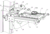
图1为本实用新型的结构示意图;Fig. 1 is the structural representation of the utility model;
图2为本实用新型的另一立体结构示意图;Fig. 2 is another three-dimensional structure schematic diagram of the present utility model;
图3为本实用新型取放片部分的结构示意图;Fig. 3 is the structural representation of the pick-and-place sheet part of the utility model;
图4为本实用新型取放片部分的仰视结构示意图;Fig. 4 is the bottom view structure schematic diagram of the utility model pick and place sheet part;
图5为本实用新型托板的结构示意图;Fig. 5 is the structural representation of the utility model pallet;
附图标记:1-安装架;2-第一滑轨;3-第一滑块;4-安装板;5-驱动电机;6-主动带轮;7-从动带轮;8-传动带;9-电缸;10-安装座;11-第二滑轨;12-第二滑块;1201-卡槽;13-托板;1301-晶圆托放部;13011-吸片孔;13012-吸片槽;14-磁耦合式无杆气缸;15-连接块;16-凸轮轴承随动器;17-液压缓冲器;18-传感器;19-防护板;20-防护壳;21-晶圆。Reference numerals: 1-installation frame; 2-first slide rail; 3-first slider; 4-installation plate; 5-drive motor; 6-drive pulley; 7-driven pulley; 8-transmission belt; 9-electric cylinder; 10-mounting seat; 11-second slide rail; 12-second slider; 1201-card slot; 13-support plate; 1301-wafer holding part; 13011-suction hole; 13012- Suction slot; 14-magnetic coupling rodless cylinder; 15-connection block; 16-cam bearing follower; 17-hydraulic buffer; 18-sensor; 19-protection plate; 20-protective shell; 21-wafer .
具体实施方式Detailed ways
下面结合具体的实施例对本实用新型进一步说明。但这些例举性实施方式的用途和目的仅用来例举本实用新型,并非对本实用新型的实际保护范围构成任何形式的任何限定,更非将本实用新型的保护范围局限于此。The present utility model will be further described below in conjunction with specific embodiments. However, the purposes and purposes of these exemplary embodiments are only used to exemplify the present invention, and do not constitute any limitation to the actual protection scope of the present invention, nor do they limit the protection scope of the present invention.
如图1至图5所示,本实施例提供了一种晶圆分选用料片取放装置,包括安装架1,安装架1上沿X轴方向滑动安装有第一驱动装置驱动的安装板4,安装板4上设有由第二驱动装置驱动、且沿Z轴方向滑动的安装座10,安装座10上沿Y轴方向滑动安装有第三驱动装置驱动的托板13,托板13末端具有一晶圆托放部1301,晶圆托放部1301的上表面开设有吸片孔13011,托板13内部开设有与吸片孔13011相连通的气道,安装端一侧开设有气道的接气口,用以实现与供气装置的气管连接。As shown in FIG. 1 to FIG. 5 , the present embodiment provides a device for picking and placing wafers for wafer sorting, including a mounting frame 1 on which a mounting plate driven by a first driving device is slidably installed along the X-axis direction. 4. The mounting plate 4 is provided with a mounting
本实施例中,X轴方向为托板13的左右位移方向,Z轴方向为托板13竖直的上下位移方向,Y轴方向为托板13的前后位移方向。In this embodiment, the X-axis direction is the left-right displacement direction of the
如图2所示,为实现安装板4的滑动安装,安装架1上沿水平方向设有两平行设置的第一滑轨2,第一滑轨2上滑动安装有第一滑块3,第一滑块3与安装板4固定连接,安装板4通过第一滑轨2、第一滑块3滑动安装于安装架1上。As shown in FIG. 2 , in order to realize the sliding installation of the mounting plate 4 , the mounting frame 1 is provided with two first slide rails 2 arranged in parallel along the horizontal direction. A sliding
第一驱动装置包括固定安装于安装架1上的驱动电机5,安装架1的一端转动安装有与驱动电机5输出轴传动连接的主动带轮6,安装架1的另一端转动安装有与主动带轮6对应设置的从动带轮7,从动带轮7与主动带轮6间架绕有传动带8,且从动带轮7与主动带轮6通过传动带8传动连接,安装板4与传动带8的一侧固定连接;驱动电机5工作,驱动传动带8转动,通过传动带8带动安装板4滑动位移。The first drive device includes a
本实施例中,驱动电机5选用安川伺服电机,第一滑轨2选用THK直线导轨,传动带8选用MISUMI同步带,重复滑动定位精度可到±0.03mm,滑动精确度高。In this embodiment, Yaskawa servo motor is used as the
第二驱动装置包括电缸9,电缸9竖直固定安装于安装板4上,安装座10与电缸9的滑板固定连接;本实施例中,电缸9选用IAI电缸,重复定位精度可达±0.02mm。通过电缸9实现对安装座10的滑动驱动,精度高,且更环保、干净,在保证刚性的同时,有效减少了气缸润滑油脂对无尘环境的污染。The second driving device includes an
如图2至图4所示,本实施例中,托板13设有两个,安装座10上设有两平行设置的第二滑轨11,第二滑轨11上分别滑动安装有第二滑块12,两托板13分别固定安装于第二滑块12上,且两托板13上下设置,两托板13的晶圆托放部1301于竖直方向上对应设置;第三驱动装置设有两套,两套第三驱动装置分别于安装座10的两侧安装,且分别与第二滑块12驱动相连。As shown in FIG. 2 to FIG. 4 , in this embodiment, there are two supporting
第三驱动装置包括固定安装于安装座10上的磁耦合式无杆气缸14,磁耦合式无杆气缸14的滑动磁体固定安装有连接块15,连接块15朝向第二滑块12的一侧安装有凸轮轴承随动器16,第二滑块12上开设有与凸轮轴承随动器16相适配的卡槽1201,凸轮轴承随动器16卡装于卡槽1201内。The third driving device includes a magnetically coupled
托板13上下设有两个,且分别通过磁耦合式无杆气缸14驱动,一次可取两个晶圆21,从而有效提高了该装置的分选效率;磁耦合式无杆气缸14的滑动磁体无动密封件、无外部泄露,满足晶圆分选的无尘需求,且磁耦合式无杆气缸14整体安装尺寸小,轴向空间小,通过磁耦合式无杆气缸14实现对托板13的驱动,以及磁耦合式无杆气缸14与第二滑轨11上下结构设计、并通过连接块15、凸轮轴承随动器16连接,更加节省了安装空间,使得取放晶圆部分结构紧凑,占用空间小,为晶圆的灵活取放提供了便利,此外,通过凸轮轴承随动器16及卡槽1201实现与第二滑块12的连接,满足磁耦合式无杆气缸14与第二滑轨11间的安装精度需求,安装难度大大降低。The
安装座10的两侧端部均对应安装有液压缓冲器17,连接块15分别于对应设置的两液压缓冲器17间设置;磁耦合式无杆气缸14行程两端设有的液压缓冲器17,能够实现安全缓冲,降低滑动冲击,起保护作用,使得取放晶圆运行平稳,且能够确保取放料片时托板13伸出长度一致,实现对晶圆21的精准取放。Both ends of the mounting
如图5所示,晶圆托放部1301的上表面开设有吸片槽13012,吸片槽13012与吸片孔13011相接,本实施例中,晶圆托放部1301的端部为圆弧状,吸片孔13011位于吸片槽13012的中间位置。晶圆托放部1301上表面开设有的吸片槽13012,增大了与晶圆21间的吸合面积,使得晶圆21在取放过程中吸合更牢固,满足了对晶圆21高效率分选的需求。As shown in FIG. 5 , a
如图4所示,安装座10上还设有用以检测花篮中晶圆放料情况的传感器18,传感器18固定安装于安装座10远离安装板4的一端底部,本实施例中,传感器18为数字激光传感器。安装座10端部安装有的传感器18,能够在取放晶圆时对盛放晶圆的花篮进行检测,检测花篮内是否无料或料片是否放满,以便于操作人员对无料或料满的花篮进行更换。As shown in FIG. 4 , the mounting
如图1所示,本实施例中,安装架1上固定安装有包覆第一驱动装置的防护板19,实现对第一驱动装置的有效防护,且避免了第一驱动装置工作时对无尘分选环境的污染;安装座10上固定安装有包覆第三驱动装置和托板13的防护壳20,实现了对第三驱动装置和托板13的有效防护,且进一步确保了无尘需求。As shown in FIG. 1 , in this embodiment, a
基于上述结构的该晶圆分选用料片取放装置,通过控制驱动电机5、电缸9和磁耦合式无杆气缸14配合动作,实现托板13的精确位移,通过托板13末端的晶圆托放部1301实现对晶圆21的取放,且晶圆托放部1301开设的吸片孔13011,能够实现对晶圆21背面的有效吸附,在对晶圆取放过程中,不会发生晶圆的掉落或位置偏移,为晶圆的准确放置提供了可靠保障;使用时,在分选机上并排放置待分选花篮和归类放置花篮,待分选花篮内放有需要分选的晶圆料片,归类放置花篮为空花篮,分别用以放置同一种类、质量的晶圆2,在分选机分选指令控制下,托板13精确运动,将待分选花篮内的晶圆料片取出并分别精确放置到相应的归类放置花篮内,完成对晶圆的归类分选。相较传统的人工分选方式,不但分选效率大大提高,降低了分选成本,有效避免了分选错误的发生,且在分选过程中,通过托板13取放晶圆21,不会对晶圆造成划伤,确保了晶圆质量不受影响,在实现晶圆归类分选的同时,能够依据晶圆衬底号从小到大按序排列放置,方便实用。Based on the above-mentioned structure, the wafer picking and placing device for sorting wafers realizes the precise displacement of the
通过该晶圆分选用料片取放装置代替人工进行晶圆分选,可二十四小时不间断工作,分选效率在380片/小时左右,分选效率大大提高,可节省约两个操作人工的人力,成本大大降低。Through the wafer sorting, the wafer picking and placing device replaces manual wafer sorting, which can work continuously for 24 hours. The sorting efficiency is about 380 pieces/hour, the sorting efficiency is greatly improved, and about two operations can be saved. Manual labor, the cost is greatly reduced.
应当理解,这些实施例的用途仅用于说明本实用新型而非意欲限制本实用新型的保护范围。此外,也应理解,在阅读了本实用新型的技术内容之后,本领域技术人员可以对本实用新型作各种改动、修改和/或变型,所有的这些等价形式同样落于本申请所附权利要求书所限定的保护范围之内。It should be understood that the purposes of these embodiments are only used to illustrate the present invention and are not intended to limit the protection scope of the present invention. In addition, it should also be understood that after reading the technical content of the present utility model, those skilled in the art can make various changes, modifications and/or modifications to the present utility model, and all these equivalent forms also fall within the appended rights of the application. within the scope of protection defined by the request.
Claims (10)
Priority Applications (1)
| Application Number | Priority Date | Filing Date | Title |
|---|---|---|---|
| CN202021357670.6U CN211265430U (en) | 2020-07-13 | 2020-07-13 | A wafer pick-and-place device for wafer sorting |
Applications Claiming Priority (1)
| Application Number | Priority Date | Filing Date | Title |
|---|---|---|---|
| CN202021357670.6U CN211265430U (en) | 2020-07-13 | 2020-07-13 | A wafer pick-and-place device for wafer sorting |
Publications (1)
| Publication Number | Publication Date |
|---|---|
| CN211265430U true CN211265430U (en) | 2020-08-14 |
Family
ID=71961881
Family Applications (1)
| Application Number | Title | Priority Date | Filing Date |
|---|---|---|---|
| CN202021357670.6U Active CN211265430U (en) | 2020-07-13 | 2020-07-13 | A wafer pick-and-place device for wafer sorting |
Country Status (1)
| Country | Link |
|---|---|
| CN (1) | CN211265430U (en) |
Cited By (3)
| Publication number | Priority date | Publication date | Assignee | Title |
|---|---|---|---|---|
| CN112540514A (en) * | 2020-12-17 | 2021-03-23 | 中国电子科技集团公司第十三研究所 | Development equipment |
| CN113649298A (en) * | 2021-08-23 | 2021-11-16 | 深圳市优界科技有限公司 | Full-automatic wafer sorting machine |
| CN114713510A (en) * | 2022-06-10 | 2022-07-08 | 成都泰美克晶体技术有限公司 | Automatic wafer sorting equipment |
-
2020
- 2020-07-13 CN CN202021357670.6U patent/CN211265430U/en active Active
Cited By (4)
| Publication number | Priority date | Publication date | Assignee | Title |
|---|---|---|---|---|
| CN112540514A (en) * | 2020-12-17 | 2021-03-23 | 中国电子科技集团公司第十三研究所 | Development equipment |
| CN113649298A (en) * | 2021-08-23 | 2021-11-16 | 深圳市优界科技有限公司 | Full-automatic wafer sorting machine |
| CN113649298B (en) * | 2021-08-23 | 2023-02-17 | 深圳市优界科技有限公司 | Full-automatic wafer sorting machine |
| CN114713510A (en) * | 2022-06-10 | 2022-07-08 | 成都泰美克晶体技术有限公司 | Automatic wafer sorting equipment |
Similar Documents
| Publication | Publication Date | Title |
|---|---|---|
| CN113426701B (en) | A chip detection and sorting equipment | |
| CN111540703B (en) | A wafer automatic sorting machine | |
| CN109499926A (en) | Battery detecting stepping all-in-one machine | |
| CN210734805U (en) | Automatic positioning device and automatic detection line comprising same | |
| CN209680603U (en) | Battery detecting stepping all-in-one machine | |
| CN109990841A (en) | A kind of dust detection cleaning device | |
| CN215894422U (en) | Material surface defect detection equipment | |
| CN108507518A (en) | A kind of lithium battery inspection equipment | |
| CN216784931U (en) | Automatic feeding equipment of camera | |
| CN216094963U (en) | Sorting testing mechanism and soft-package battery balance sorting testing machine | |
| CN220970007U (en) | New energy source lug on-line detector | |
| CN213455333U (en) | Appearance size detection equipment | |
| CN216094961U (en) | Feeding conveying mechanism and soft-package battery balance sorting testing machine | |
| CN215542830U (en) | Flexible screen double-sided 3D detection equipment | |
| CN213103293U (en) | Mobile phone card support elastic sheet detection machine | |
| CN210899269U (en) | A device for automatic detection and wiping of laser codes for mobile phone screens | |
| CN113044563A (en) | Feeding mechanism and belt cleaning device | |
| CN116698745B (en) | Fully automated AOI retesting equipment | |
| CN217314594U (en) | Magnet size automatic detection equipment | |
| CN217212318U (en) | Chip double-side detection equipment | |
| JP7645146B2 (en) | Processing device and manufacturing method of processed products | |
| CN210392890U (en) | Silicon chip appearance detection device | |
| CN223352237U (en) | A four-direction detection module for visual inspection equipment | |
| CN211141882U (en) | Feeding and discharging device of hot bending machine | |
| CN116393414A (en) | A sorting and unloading device for silicon wafers |
Legal Events
| Date | Code | Title | Description |
|---|---|---|---|
| GR01 | Patent grant | ||
| GR01 | Patent grant | ||
| CP01 | Change in the name or title of a patent holder | ||
| CP01 | Change in the name or title of a patent holder |
Address after: 261000 west area of the third photoelectric Park, north of Yuqing street, west of Yinfeng Road, high tech Zone, Weifang City, Shandong Province Patentee after: Yuanxu Semiconductor Technology Co.,Ltd. Address before: 261000 west area of the third photoelectric Park, north of Yuqing street, west of Yinfeng Road, high tech Zone, Weifang City, Shandong Province Patentee before: SHANDONG NOVOSHINE OPTOELECTRONICS Co.,Ltd. |