CN211247933U - Elevator door plant punching device - Google Patents
Elevator door plant punching device Download PDFInfo
- Publication number
- CN211247933U CN211247933U CN201921772111.9U CN201921772111U CN211247933U CN 211247933 U CN211247933 U CN 211247933U CN 201921772111 U CN201921772111 U CN 201921772111U CN 211247933 U CN211247933 U CN 211247933U
- Authority
- CN
- China
- Prior art keywords
- punching
- punch
- head
- elevator door
- hydraulic oil
- Prior art date
- Legal status (The legal status is an assumption and is not a legal conclusion. Google has not performed a legal analysis and makes no representation as to the accuracy of the status listed.)
- Expired - Fee Related
Links
- 238000004080 punching Methods 0.000 title claims abstract description 31
- 239000010720 hydraulic oil Substances 0.000 claims abstract description 11
- 239000002699 waste material Substances 0.000 abstract description 19
- 238000000034 method Methods 0.000 abstract description 8
- 230000002035 prolonged effect Effects 0.000 abstract description 5
- 239000003292 glue Substances 0.000 description 2
- 238000005452 bending Methods 0.000 description 1
- 238000004519 manufacturing process Methods 0.000 description 1
- 238000003825 pressing Methods 0.000 description 1
Images


Landscapes
- Elevator Door Apparatuses (AREA)
Abstract
The utility model relates to an elevator door plant punching device belongs to elevator door plant processing art field. The punching head mainly comprises a fixed seat, a hydraulic oil cylinder, a punching head and a jacking block, wherein a die hole is formed in the fixed seat, the bottom of a cylinder body of the hydraulic oil cylinder is fixedly arranged at the bottom of the fixed seat, the punching head is fixedly arranged at the end part of a piston rod of the hydraulic oil cylinder, a long hole is formed in one side edge of the punching head, the jacking block is provided with a fixing strip and a thimble, the fixing strip of the jacking block is fixedly arranged on the fixed seat, and the thimble is positioned in a cavity of the punching head; the die holes are formed in the fixed seat, and the hydraulic oil cylinder applies pressure to the workpiece through the punch to realize punching, so that the structure is simple; the ejector pin is used for removing the waste once in the process of retracting the punch pin every time, so that the situation that the waste is stuck to the head of the punch pin is avoided, the precision of next punching is ensured, and the working efficiency and the yield are improved; the waste at the head part of the male die is removed in time, so that the head part of the male die can radiate heat in time, and the service life of the male die is prolonged.
Description
Technical Field
The utility model belongs to elevator door plant processing art field, in particular to elevator door plant punching device.
Background
Punching is an important process in the production process of the elevator door plate. The punching process is to use special dies (male die and female die) to apply certain pressure on the workpiece, so as to punch through holes with various shapes on the workpiece. However, the condition that the waste material glues and stays in the terrace die head often appears in current punching equipment, the great reduction of precision that punches a hole after this kind of condition appears, can not reach the processing requirement when serious, lead to the rejection rate to increase, need artifical clearance waste material, moreover, need shut down when clearing up the waste material and just can operate, reduced work efficiency, but the terrace die head long time impact work piece still can produce a large amount of heats moreover, the heat in time gives off the life that still can reduce the terrace die.
Disclosure of Invention
In order to overcome the problems in the background art, the utility model provides an elevator door plate punching device which can remove the waste once after each punching is completed, thereby avoiding the situation that the waste is stuck at the head part of a male die, ensuring the precision of the next punching, and improving the working efficiency and the yield; the waste at the head part of the male die is removed in time, so that the head part of the male die can radiate heat in time, and the service life of the male die is prolonged.
In order to achieve the above purpose, the utility model is realized by the following technical scheme: the utility model provides an elevator door plant punching device mainly includes fixing base, hydraulic cylinder, drift, kicking block, the fixing base on be equipped with first fixed plate, second fixed plate, third fixed plate, be equipped with the nib on the first fixed plate, hydraulic cylinder's cylinder body bottom fixed mounting is in the bottom of the third fixed plate of fixing base, drift fixed mounting is at the tip of hydraulic cylinder's piston rod, the drift be the hollow tube, a side is equipped with rectangular hole, the kicking block is equipped with fixed strip and thimble, the fixed strip fixed mounting of kicking block is in the bottom of the second fixed plate of fixing base, through the rectangular hole of drift, the thimble is in the cavity of drift.
And a guide hole matched with the punch is formed in the second fixing plate of the fixing seat.
The utility model has the advantages that:
the utility model has the advantages that the fixed seat is provided with the die hole (the female die), the hydraulic oil cylinder applies pressure to the workpiece through the punch (the male die) to realize punching, and the structure is simple and practical; the ejector pin is used for removing the waste once in the process of retracting the punch pin every time, so that the situation that the waste is stuck to the head of the punch pin is avoided, the precision of next punching is ensured, and the working efficiency and the yield are improved; the waste at the head part of the male die is removed in time, so that the head part of the male die can radiate heat in time, and the service life of the male die is prolonged.
Drawings
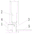
Fig. 1 is a perspective view of the present invention.
Fig. 2 is a schematic perspective view of the working state of the present invention.
Fig. 3 is a partially enlarged schematic view of a portion a of fig. 2.
Fig. 4 is a perspective view of the top block of the present invention.
Fig. 5 is a schematic view of the working state of the present invention.
Detailed Description
In order to make the objects, technical solutions and advantages of the present invention clearer, the following will explain in detail a preferred embodiment of the present invention with reference to the accompanying drawings to facilitate understanding of the skilled person.
The utility model discloses an elevator door plant punching device, an elevator door plant punching device mainly include fixing base 1, hydraulic cylinder 2, drift 3, kicking block 4, fixing base 1 on be equipped with first fixed plate 11, second fixed plate 12, third fixed plate 13, be equipped with nib 14 on the first fixed plate 11, hydraulic cylinder 2's cylinder body bottom fixed mounting is in the bottom of the third fixed plate 13 of fixing base 1, drift 3 fixed mounting is in the tip of hydraulic cylinder 2's piston rod, drift 3 be the hollow tube, one side is equipped with rectangular hole 31, kicking block 4 is equipped with fixed strip 41 and thimble 42, fixed strip 41 fixed mounting of kicking block 4 is in the bottom of the second fixed plate 12 of fixing base 1, through the rectangular hole 31 of drift 3, thimble 42 is in the cavity of drift 3; the utility model is fixed on a workbench for use, is matched with a feeding device on the workbench and an elevator door plate feeding device for use, and realizes punching by arranging a die hole 14 as a (female) on a fixed seat 1 and applying pressure to a workpiece 5 by a hydraulic oil cylinder 2 as a (male) through a punch 3, as shown in figure 5, the structure is simple and practical; the ejector pin 42 is used for removing the waste once in the process of retracting the punch 3 each time, so that the situation that the waste is stuck to the head of the punch is avoided, the precision of next punching is ensured, and the working efficiency and the yield are improved; the waste at the head part of the male die is removed in time, so that the head part of the male die can radiate heat in time, and the service life of the male die is prolonged.
A guide hole 15 matched with the punch 3 is arranged on the second fixing plate 12 of the fixing seat 1; the matching precision of the punch 3 and the die hole 14 is ensured through the guide hole 15, and meanwhile, the hydraulic oil cylinder 2 is prevented from being subjected to bending force in the working process.
The working process is as follows:
the utility model discloses fix and use on the workstation, loading attachment and elevator door plant feeding device on the cooperation workstation use, after elevator door plant feeds the completion, hydraulic cylinder 2 begins to stretch out, promote drift 3 downstream, when drift 3 and work piece 5 contact, hydraulic cylinder 2 continues to stretch out, exert pressure to work piece 5 through drift 3, when the pressure of exerting is enough big, form the hole with the corresponding shape of nib 14 and drift 3 on the work piece 5, as shown in fig. 5, the completion back punches a hole, hydraulic cylinder begins the withdrawal, pulling drift 3 upward movement, when drift 3 moves to the position shown in fig. 1, fixed thimble 42 glues the waste material of staying with drift 3 head ejecting and drops, the work of punching a hole is accomplished, move elevator door plant through feeding device, continue the work of punching a hole of next position.
The utility model has the advantages that the die holes are arranged on the fixed seat, the hydraulic oil cylinder applies pressure to the workpiece through the punch head to realize punching, and the structure is simple and practical; the ejector pin is used for removing the waste once in the process of retracting the punch pin every time, so that the situation that the waste is stuck to the head of the punch pin is avoided, the precision of next punching is ensured, and the working efficiency and the yield are improved; the waste at the head part of the male die is removed in time, so that the head part of the male die can radiate heat in time, and the service life of the male die is prolonged.
Finally, it is noted that the above-mentioned preferred embodiments illustrate rather than limit the invention, and that, although the invention has been described in detail with reference to the above-mentioned preferred embodiments, it will be understood by those skilled in the art that various changes in form and details may be made therein without departing from the scope of the invention as defined by the appended claims.
Claims (2)
1. The utility model provides an elevator door plant punching device which characterized in that: the elevator door plate punching device comprises a fixed seat (1), a hydraulic oil cylinder (2), a punch (3) and a top block (4), a first fixing plate (11), a second fixing plate (12) and a third fixing plate (13) are arranged on the fixing seat (1), a die hole (14) is arranged on the first fixing plate (11), the bottom of the cylinder body of the hydraulic oil cylinder (2) is fixedly arranged at the bottom of the third fixing plate (13) of the fixing seat (1), the punch (3) is fixedly arranged at the end part of the piston rod of the hydraulic oil cylinder (2), the punch (3) is a hollow tube, one side of the punch is provided with a long hole (31), the ejector block (4) is provided with a fixing strip (41) and an ejector pin (42), the fixing strip (41) of the ejector block (4) is fixedly arranged at the bottom of the second fixing plate (12) of the fixing seat (1), the ejector pin (42) is positioned in the cavity of the punch head (3) through the long hole (31) of the punch head (3).
2. The elevator door panel punching apparatus according to claim 1, wherein: and a guide hole (15) matched with the punch (3) is formed in the second fixing plate (12) of the fixing seat (1).
Priority Applications (1)
| Application Number | Priority Date | Filing Date | Title |
|---|---|---|---|
| CN201921772111.9U CN211247933U (en) | 2019-10-22 | 2019-10-22 | Elevator door plant punching device |
Applications Claiming Priority (1)
| Application Number | Priority Date | Filing Date | Title |
|---|---|---|---|
| CN201921772111.9U CN211247933U (en) | 2019-10-22 | 2019-10-22 | Elevator door plant punching device |
Publications (1)
| Publication Number | Publication Date |
|---|---|
| CN211247933U true CN211247933U (en) | 2020-08-14 |
Family
ID=71987895
Family Applications (1)
| Application Number | Title | Priority Date | Filing Date |
|---|---|---|---|
| CN201921772111.9U Expired - Fee Related CN211247933U (en) | 2019-10-22 | 2019-10-22 | Elevator door plant punching device |
Country Status (1)
| Country | Link |
|---|---|
| CN (1) | CN211247933U (en) |
Cited By (1)
| Publication number | Priority date | Publication date | Assignee | Title |
|---|---|---|---|---|
| CN112873602A (en) * | 2020-12-02 | 2021-06-01 | 浙江翔宇密封件有限公司 | Prilling granulator of sealing washer production usefulness for high-speed railway |
-
2019
- 2019-10-22 CN CN201921772111.9U patent/CN211247933U/en not_active Expired - Fee Related
Cited By (1)
| Publication number | Priority date | Publication date | Assignee | Title |
|---|---|---|---|---|
| CN112873602A (en) * | 2020-12-02 | 2021-06-01 | 浙江翔宇密封件有限公司 | Prilling granulator of sealing washer production usefulness for high-speed railway |
Similar Documents
| Publication | Publication Date | Title |
|---|---|---|
| CN205147079U (en) | Plate electrode blanking and punching compound die | |
| CN202921783U (en) | In-mold riveting die for heat sink terminal | |
| CN204182800U (en) | A kind of compound punching structure for punch level progressive die | |
| CN116900103B (en) | Wiper arm combination stamping die | |
| CN107252846A (en) | A kind of computer buckle processing mold | |
| CN101912924A (en) | Hydraulic oil radiator mainboard stamping die and using method thereof | |
| CN103433377A (en) | Blanking, punching, flanging and forming composite die | |
| CN107096830A (en) | A kind of computer buckle diel with holes | |
| CN111760976B (en) | One-step blanking stretch punching continuous die | |
| CN205702038U (en) | A kind of auto partition hole punched device | |
| CN221289222U (en) | One-step forming die for forming holes in side surfaces of cylindrical workpieces and flanging around holes | |
| CN202106018U (en) | Deburring die for periphery of automobile water pump housing die casting | |
| CN217412224U (en) | Stripping structure for progressive die and progressive die | |
| CN216369770U (en) | Die with stamping appearance and hole burr in same direction | |
| CN210098668U (en) | High-precision shaft hole punching die for plate material | |
| CN211588229U (en) | Inclined plane blanking mechanism of progressive stamping die | |
| CN203426245U (en) | Small hole stamping die | |
| CN210847937U (en) | Hole flanging and flanging composite die for end cover | |
| CN208373986U (en) | A kind of turret head molding die of super long high strength bolt | |
| CN204974966U (en) | Part forming die | |
| CN218517552U (en) | Composite stamping die for punching, flanging and forming | |
| CN213591568U (en) | Positioning and feeding mechanism | |
| CN212760927U (en) | Lossless forging forming equipment for steel | |
| CN222659863U (en) | Cold heading stretching die assembly | |
| CN104889256A (en) | Part forming die |
Legal Events
| Date | Code | Title | Description |
|---|---|---|---|
| GR01 | Patent grant | ||
| GR01 | Patent grant | ||
| CF01 | Termination of patent right due to non-payment of annual fee | ||
| CF01 | Termination of patent right due to non-payment of annual fee |
Granted publication date: 20200814 |