CN211239632U - High-speed dismouting frock of directly driving motor - Google Patents
High-speed dismouting frock of directly driving motor Download PDFInfo
- Publication number
- CN211239632U CN211239632U CN202020395967.5U CN202020395967U CN211239632U CN 211239632 U CN211239632 U CN 211239632U CN 202020395967 U CN202020395967 U CN 202020395967U CN 211239632 U CN211239632 U CN 211239632U
- Authority
- CN
- China
- Prior art keywords
- bearing
- speed
- motor
- dismouting
- substitute
- Prior art date
- Legal status (The legal status is an assumption and is not a legal conclusion. Google has not performed a legal analysis and makes no representation as to the accuracy of the status listed.)
- Active
Links
Images

Abstract
The utility model discloses a high-speed dismouting frock of directly driving motor, including guide bar and substitute bearing, guide bar one end is equipped with the external screw thread, passes through screw thread fixed connection with high-speed motor shaft one end, the external diameter of guide bar is the same with the high-speed back bearing internal diameter that directly drives in the motor, substitute the bearing and be used for replacing the high-speed back bearing that directly drives in the motor when the dismouting, the assembly is in the high-speed stator module that directly drives the motor, and the stator module cover that is equipped with substitute the bearing during the dismouting is established on the guide bar, replaces the bearing and accomplishes the dismouting of high-speed motor with the guide bar cooperation. The utility model discloses can solve the dismouting problem that causes the damage to parts such as bearing, axle, stator and rotor when the high-speed motor that directly drives of dismouting to simple structure, easy operation, the manufacturing degree of difficulty and low in manufacturing cost.
Description
Technical Field
The utility model relates to a dismouting frock technical field specifically is a high-speed dismouting frock that directly drives motor.
Background
In order to improve the energy utilization efficiency, a driving power system is gradually developed from a traditional low-speed motor-gear system to a high-speed direct-drive motor, and is applied to the aspects of mechanical manufacturing, automation, electronic semiconductors, measurement, medical technology and the like. The direct-drive motor simplifies the overall mechanical design, and the whole motor system is very compact, so that the direct-drive motor is difficult to disassemble and assemble and is easy to cause different degrees of damage to components such as shafts, bearings, stators and rotors; especially, the stator and the rotor are relatively small in clearance and relatively long in matching length, and the stator matching part is a permanent magnet, so that the stator and the rotor are very strong in magnetism and inconvenient to assemble and disassemble. Therefore, it is very important to design a high-speed direct drive motor dismounting protection tool.
SUMMERY OF THE UTILITY MODEL
To the defect among the prior art, the utility model provides a high-speed dismouting frock of directly driving motor can solve the dismouting problem that causes the damage to parts such as bearing, axle, stator and rotor when the high-speed motor that directly drives of dismouting to simple structure, easy operation, the manufacturing degree of difficulty and low in manufacturing cost.
A dismouting frock of high-speed motor that directly drives, including guide bar and substitute bearing, guide bar one end is equipped with the external screw thread, passes through screw thread fixed connection with high-speed motor shaft one end, the external diameter of guide bar is the same with the high-speed back bearing internal diameter that directly drives in the motor, substitute the bearing and be used for replacing the high-speed back bearing that directly drives in the motor when the dismouting, the assembly is in the high-speed stator module that directly drives the motor, the stator module cover that is equipped with substitute bearing during the dismouting establishes on the guide bar, replaces the bearing and accomplishes the dismouting of high-speed motor with the guide bar cooperation.
Further, the fit clearance of the substitute bearing and the guide bar is generally less than 0.1 mm.
Furthermore, the guide rod and the substitute bearing are made of materials with low hardness. The damage between parts during stator and rotor assembly can be reduced.
Further, the material of the guide rod is LY12, and the material of the substitute bearing is LD 5.
The utility model has the advantages that:
the utility model discloses an adopt the guide bar and replace the bearing, directly drive motor shaft fixed connection with guide bar and high speed, earlier change the back bearing in the motor into replacing the bearing during dismouting, will replace the bearing assembly in the stator module of motor, cooperate the equipment or dismantle the stator module of motor with the guide bar again, can reduce the damage that parts such as bearing, axle, stator and rotor caused when the dismouting directly drives the motor at a high speed, frock simple structure, convenient operation is swift to the manufacturing degree of difficulty and low in manufacturing cost.
Drawings
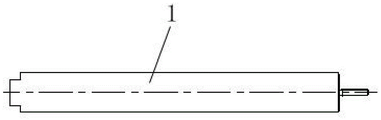
Fig. 1 is a schematic structural view of a guide bar of the present invention;
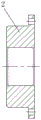
FIG. 2 is a schematic structural view of an alternative bearing of the present invention;
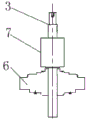
FIG. 3 is an assembly view of a front bearing seat, a permanent magnet and a high-speed motor shaft in the high-speed driving motor;
FIG. 4 is a schematic view of the guide bar assembled with the high speed motor shaft;
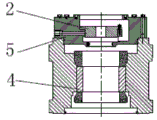
FIG. 5 is a schematic view of an alternative bearing and stator assembly;
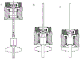
figure 6 is the process chart of using the utility model discloses high-speed driving motor of frock equipment.
In the drawings: 1-guide rod, 2-substitute bearing, 3-high-speed motor shaft, 4-stator, 5-rear bearing seat, 6-front bearing seat and 7-permanent magnet.
Detailed Description
The embodiments of the present invention will be described in further detail with reference to the accompanying drawings.
As shown in fig. 1-6, a disassembly and assembly tool for a high-speed direct-drive motor comprises a guide rod 1 and a substitute bearing 2, wherein an external thread is arranged at one end of the guide rod 1 and fixedly connected with one end of a high-speed motor shaft 3 through a thread, the outer diameter of the guide rod 1 is the same as the inner diameter of a rear bearing in the high-speed direct-drive motor, the substitute bearing 2 is used for replacing the rear bearing in the high-speed direct-drive motor during disassembly and assembly and is assembled in a stator assembly of the high-speed direct-drive motor, the stator assembly comprises a stator 4, a rear bearing seat 5 and a rear bearing, the stator assembly provided with the substitute bearing during disassembly and assembly is sleeved on the guide rod 1, the substitute bearing 2 is matched with the guide rod 1 to complete disassembly and assembly of the high-speed direct-drive motor.
In this embodiment, in order to reduce damage to internal components such as a bearing, a shaft, a stator and a rotor when the high-speed driving motor is dismounted and mounted, the material of the guide rod and the substitute bearing is low in hardness, for example, the guide rod is LY12, the substitute bearing is LD5, and the like, and the substitute bearing is in small clearance fit with the guide rod when being assembled, and the fit clearance is generally smaller than 0.1 mm.
As shown in fig. 6, a of fig. 6 shows a schematic view of the stator assembly starting to be assembled to the guide bar,
b in fig. 6 shows a schematic view of the stator assembly with the guide bar in the middle of assembly;
c in figure 6 shows the stator assembly fitted in place with the guide bar.
The utility model is used for dismouting high-speed driving motor's working process:
the tool is used in the assembly of the motor:
1. after the front bearing seat and the high-speed motor shaft are assembled, the front bearing seat and the high-speed motor shaft are vertically placed, as shown in fig. 3;
2. connecting the guide rod to a high-speed motor shaft, and assembling the guide rod on a stator assembly instead of a bearing, wherein the stator assembly is assembled by a stator rear bearing seat and a shell, as shown in fig. 4 and 5;
3. gradually assembling the stator assembly parts in place with the guide bars, as shown in fig. 6;
4. and taking down the substitute bearing and the guide rod, and finishing the installation of parts such as a rear bearing, a rear oil seal and the like.
The tool is used in steps and reversely used in the process of assembling the motor when the motor is disassembled, and the tool comprises the following specific steps:
1. vertically placing a motor;
2. firstly, removing the rear bearing end cover, the rear bearing and the rear oil seal, connecting the guide rod into the high-speed motor shaft, and installing the substitute bearing, as shown in fig. 6;
3. slowly pull the motor housing out (stator + rear bearing housing), as shown in fig. 6;
4. and after the motor is pulled out, other parts of the motor are dismantled, and then the dismantling work can be completed.
The utility model discloses an adopt simple dismouting frock, can solve the dismouting problem that causes the damage to parts such as bearing, axle, stator and rotor when the high-speed motor that directly drives of dismouting, simple structure, the simple operation makes the degree of difficulty and low in manufacturing cost, the extensive popularization of being convenient for.
Finally, it should be noted that: the above embodiments are only used to illustrate the technical solution of the present invention, and not to limit it; although the present invention has been described in detail with reference to the foregoing embodiments, it will be understood by those skilled in the art; the technical solutions described in the foregoing embodiments may still be modified, or some or all of the technical features may be equivalently replaced; such modifications and substitutions do not substantially depart from the scope of the embodiments of the present invention, and are intended to be covered by the claims and the specification.
Claims (4)
1. The utility model provides a dismouting frock of high-speed direct drive motor which characterized in that: the assembly structure comprises a guide rod and a substitute bearing, wherein an external thread is arranged at one end of the guide rod and is fixedly connected with one end of a high-speed motor shaft through a thread, the outer diameter of the guide rod is the same as the inner diameter of a rear bearing in the high-speed direct-drive motor, the substitute bearing is used for substituting the rear bearing in the high-speed direct-drive motor during disassembly and assembly and is assembled in a stator assembly of the high-speed direct-drive motor, the stator assembly provided with the substitute bearing during disassembly and assembly is sleeved on the guide rod, and the substitute bearing is matched with the guide rod to complete.
2. The tool for disassembling and assembling the high-speed direct-drive motor according to claim 1, is characterized in that: the fit clearance of the substitute bearing and the guide rod is generally less than 0.1 mm.
3. The tool for disassembling and assembling the high-speed direct-drive motor according to claim 1, is characterized in that: the guide rod and the substitute bearing are made of materials with low hardness.
4. The tool for disassembling and assembling the high-speed direct-drive motor according to claim 3, is characterized in that: the guide rod material is LY12, and the substitute bearing material is LD 5.
Priority Applications (1)
| Application Number | Priority Date | Filing Date | Title |
|---|---|---|---|
| CN202020395967.5U CN211239632U (en) | 2020-03-25 | 2020-03-25 | High-speed dismouting frock of directly driving motor |
Applications Claiming Priority (1)
| Application Number | Priority Date | Filing Date | Title |
|---|---|---|---|
| CN202020395967.5U CN211239632U (en) | 2020-03-25 | 2020-03-25 | High-speed dismouting frock of directly driving motor |
Publications (1)
| Publication Number | Publication Date |
|---|---|
| CN211239632U true CN211239632U (en) | 2020-08-11 |
Family
ID=71917092
Family Applications (1)
| Application Number | Title | Priority Date | Filing Date |
|---|---|---|---|
| CN202020395967.5U Active CN211239632U (en) | 2020-03-25 | 2020-03-25 | High-speed dismouting frock of directly driving motor |
Country Status (1)
| Country | Link |
|---|---|
| CN (1) | CN211239632U (en) |
-
2020
- 2020-03-25 CN CN202020395967.5U patent/CN211239632U/en active Active
Similar Documents
| Publication | Publication Date | Title |
|---|---|---|
| CN108808973B (en) | Double-shaft magnetic suspension bearing reluctance motor | |
| CN109256914A (en) | One kind is for permanent magnet synchronous motor assembly device and assembly method | |
| CN211239632U (en) | High-speed dismouting frock of directly driving motor | |
| CN210977758U (en) | Permanent-magnet direct-drive wind driven generator | |
| CN203046275U (en) | Crank shaft and servo motor integrated structure | |
| CN201422054Y (en) | Coupling box provided with driving motor | |
| CN202140314U (en) | Permanent-magnet straight-linkage type screw compressor | |
| CN203180718U (en) | Connection structure between air compressor and driving motor thereof | |
| CN209976801U (en) | Two-stage direct-drive vane electric pump without motor shaft | |
| CN210536426U (en) | Floating type mounting structure of semi-direct-drive permanent magnet motor of beam-pumping unit | |
| CN110635645B (en) | High-efficiency speed regulating method of brushless motor | |
| CN207810484U (en) | A kind of built-in electric roller directly driven with permanent magnet synchronous motor | |
| CN216672727U (en) | Rear permanent magnet synchronous electric host structure | |
| CN111577772B (en) | Electric drawing type bearing ejection device | |
| CN210927382U (en) | Magnetic gear composite motor assembly mould | |
| CN201422058Y (en) | Negative pressure device | |
| CN214674725U (en) | Direct current driving motor structure | |
| CN213637373U (en) | Gear shaft mounting structure of servo press | |
| CN201286041Y (en) | Servo motor | |
| CN218387061U (en) | External rotor motor | |
| CN218669321U (en) | Semi-direct-drive oil pumping unit | |
| CN220492721U (en) | Shell rotary output motor | |
| CN212494572U (en) | Driving mechanism of wire drawing machine | |
| CN215973511U (en) | High-efficiency energy-saving electric roller | |
| CN214724228U (en) | Switched reluctance motor servo driving device for industrial robot |
Legal Events
| Date | Code | Title | Description |
|---|---|---|---|
| GR01 | Patent grant | ||
| GR01 | Patent grant |