CN211238404U - Battery module - Google Patents
Battery module Download PDFInfo
- Publication number
- CN211238404U CN211238404U CN201922166287.6U CN201922166287U CN211238404U CN 211238404 U CN211238404 U CN 211238404U CN 201922166287 U CN201922166287 U CN 201922166287U CN 211238404 U CN211238404 U CN 211238404U
- Authority
- CN
- China
- Prior art keywords
- insulating sheet
- end plate
- insulating
- battery module
- glue
- Prior art date
- Legal status (The legal status is an assumption and is not a legal conclusion. Google has not performed a legal analysis and makes no representation as to the accuracy of the status listed.)
- Active
Links
Images


Classifications
-
- Y—GENERAL TAGGING OF NEW TECHNOLOGICAL DEVELOPMENTS; GENERAL TAGGING OF CROSS-SECTIONAL TECHNOLOGIES SPANNING OVER SEVERAL SECTIONS OF THE IPC; TECHNICAL SUBJECTS COVERED BY FORMER USPC CROSS-REFERENCE ART COLLECTIONS [XRACs] AND DIGESTS
- Y02—TECHNOLOGIES OR APPLICATIONS FOR MITIGATION OR ADAPTATION AGAINST CLIMATE CHANGE
- Y02E—REDUCTION OF GREENHOUSE GAS [GHG] EMISSIONS, RELATED TO ENERGY GENERATION, TRANSMISSION OR DISTRIBUTION
- Y02E60/00—Enabling technologies; Technologies with a potential or indirect contribution to GHG emissions mitigation
- Y02E60/10—Energy storage using batteries
-
- Y—GENERAL TAGGING OF NEW TECHNOLOGICAL DEVELOPMENTS; GENERAL TAGGING OF CROSS-SECTIONAL TECHNOLOGIES SPANNING OVER SEVERAL SECTIONS OF THE IPC; TECHNICAL SUBJECTS COVERED BY FORMER USPC CROSS-REFERENCE ART COLLECTIONS [XRACs] AND DIGESTS
- Y02—TECHNOLOGIES OR APPLICATIONS FOR MITIGATION OR ADAPTATION AGAINST CLIMATE CHANGE
- Y02P—CLIMATE CHANGE MITIGATION TECHNOLOGIES IN THE PRODUCTION OR PROCESSING OF GOODS
- Y02P70/00—Climate change mitigation technologies in the production process for final industrial or consumer products
- Y02P70/50—Manufacturing or production processes characterised by the final manufactured product
Landscapes
- Battery Mounting, Suspending (AREA)
Abstract
本实用新型公开一种电池模组,包括外包围板以及电芯,外包围板包括两个相对的侧板以及设置在两个侧板之间的端板,两个端板沿着侧板长度方向间隔分布,侧板和端板共同围设形成容纳腔,电芯设置在容纳腔中,端板与电芯之间设置有第一绝缘片,第一绝缘片贯穿开设有至少一个粘接孔,粘接孔内填充绝缘胶,第一绝缘片通过绝缘胶分别与端板和电芯粘接。由于粘接孔贯穿第一绝缘片,一方面,可以在粘接孔内存储较多的绝缘胶,增大绝缘胶的厚度,降低第一绝缘片从端板和电芯上脱离的风险;另一方面,在实际涂胶时,不需要在第一绝缘片相对的两侧面均涂满粘胶剂,仅仅是在粘接孔内填充绝缘胶,节省了绝缘胶的使用量,以及缩短涂胶的时间。
The utility model discloses a battery module, which comprises an outer enclosure plate and a battery core. The outer enclosure plate includes two opposite side plates and an end plate arranged between the two side plates. The two end plates are along the length of the side plates. The directions are spaced apart, the side plate and the end plate are jointly formed to form an accommodation cavity, the cell is arranged in the accommodation cavity, a first insulating sheet is arranged between the end plate and the electric core, and at least one bonding hole is formed through the first insulating sheet , the bonding hole is filled with insulating glue, and the first insulating sheet is respectively bonded to the end plate and the electric core through the insulating glue. Since the bonding hole runs through the first insulating sheet, on the one hand, more insulating glue can be stored in the bonding hole, the thickness of the insulating glue can be increased, and the risk of the first insulating sheet being detached from the end plate and the cell can be reduced; On the one hand, in the actual application of glue, it is not necessary to apply glue on the opposite sides of the first insulating sheet, but only fill the insulating glue in the bonding hole, which saves the amount of insulating glue and shortens the glue application. time.
Description
技术领域technical field
本实用新型涉及电池技术领域,尤其涉及一种电池模组。The utility model relates to the technical field of batteries, in particular to a battery module.
背景技术Background technique
动力电池模组一般包括外包围板以及设置在外包围板内部的电芯,外包围板由侧板、顶板以及端板围设形成,为了保证端板与电芯之间的绝缘性,需要在端板与电芯之间设置绝缘片。现有技术中,在绝缘片相对两侧面涂满粘胶剂,使得绝缘片通过粘胶剂分别与电芯和端板粘接。但是此种设计方式存在以下不足:由于需要分别在绝缘片的两侧面涂胶,一方面,造成粘胶剂的浪费,另一方面,需要分步对绝缘片进行涂胶,增加涂胶的工作量。The power battery module generally includes an outer enclosure plate and a battery cell arranged inside the outer enclosure plate. The outer enclosure plate is surrounded by a side plate, a top plate and an end plate. In order to ensure the insulation between the end plate and the battery cell, it is necessary to An insulating sheet is arranged between the board and the cell. In the prior art, the opposite sides of the insulating sheet are filled with adhesive, so that the insulating sheet is bonded to the battery core and the end plate respectively through the adhesive. However, this design method has the following shortcomings: due to the need to apply glue on both sides of the insulating sheet, on the one hand, the waste of adhesive is caused; quantity.
实用新型内容Utility model content
本实用新型的目的在于:提供一种电池模组,其能克服上述的不足。The purpose of the present invention is to provide a battery module which can overcome the above deficiencies.
为达到此目的,本实用新型采用以下技术方案:In order to achieve this purpose, the utility model adopts the following technical solutions:
提供一种电池模组,包括外包围板以及电芯,所述外包围板包括两个相对的侧板以及设置在两个所述侧板之间的端板,两个所述端板沿着所述侧板长度方向间隔分布,所述侧板和所述端板共同围设形成容纳腔,所述电芯设置在所述容纳腔中,所述端板与所述电芯之间设置有第一绝缘片,所述第一绝缘片贯穿开设有至少一个粘接孔,所述粘接孔内填充绝缘胶,所述第一绝缘片通过所述绝缘胶分别与所述端板和所述电芯粘接。A battery module is provided, comprising an outer enclosure plate and a battery core, the outer enclosure plate includes two opposite side plates and an end plate arranged between the two side plates, the two end plates are along the The side plates are distributed at intervals in the length direction, the side plates and the end plates are jointly formed to form a receiving cavity, the battery core is arranged in the receiving cavity, and a space is arranged between the end plate and the battery core. A first insulating sheet, at least one bonding hole is formed through the first insulating sheet, and insulating glue is filled in the bonding hole, and the first insulating sheet is respectively connected with the end plate and the end plate through the insulating glue. Cell bonding.
作为所述的电池模组的一种优选的技术方案,所述第一绝缘片上间隔设置有四个所述粘接孔。As a preferred technical solution of the battery module, the first insulating sheet is provided with four bonding holes at intervals.
作为所述的电池模组的一种优选的技术方案,所有的所述粘接孔的面积之和与所述第一绝缘片正对所述端板一侧面的面积之比为:1/2~3/4。As a preferred technical solution of the battery module, the ratio of the sum of the areas of all the bonding holes to the area of the side of the first insulating sheet facing the end plate is: 1/2 ~3/4.
作为所述的电池模组的一种优选的技术方案,所述粘接孔的孔壁呈波浪结构;As a preferred technical solution of the battery module, the hole wall of the bonding hole is in a wavy structure;
或,or,
所述粘接孔的孔壁呈锯齿结构。The hole wall of the bonding hole is in a sawtooth structure.
作为所述的电池模组的一种优选的技术方案,所述第一绝缘片的上端朝向背离所述端板的方向凸设有定位钩,所述定位钩与所述电芯的顶部连接。As a preferred technical solution of the battery module, a positioning hook is protruded from the upper end of the first insulating sheet toward the direction away from the end plate, and the positioning hook is connected to the top of the battery cell.
作为所述的电池模组的一种优选的技术方案,所述端板靠近所述第一绝缘片的一侧间隔凹设有两个第一凹槽,所述第一凹槽沿所述端板高度方向延伸,所述粘接孔位于两个所述第一凹槽之间。As a preferred technical solution of the battery module, a side of the end plate close to the first insulating sheet is provided with two first grooves at intervals, and the first grooves are along the end of the end plate. The board extends in the height direction, and the bonding hole is located between the two first grooves.
作为所述的电池模组的一种优选的技术方案,所述第一凹槽分别连通所述端板的上端和下端。As a preferred technical solution of the battery module, the first grooves are respectively connected to the upper end and the lower end of the end plate.
作为所述的电池模组的一种优选的技术方案,所述端板靠近所述第一绝缘片的一侧面间隔设置有两个第二凹槽,所述第一凹槽位于所述粘接孔与所述第二凹槽之间,所述侧板与所述电芯之间设置有第二绝缘片,所述第二绝缘片端部插至所述第二凹槽内。As a preferred technical solution of the battery module, a side surface of the end plate close to the first insulating sheet is provided with two second grooves at intervals, and the first grooves are located in the bonding area. A second insulating sheet is arranged between the hole and the second groove, and between the side plate and the battery core, and the end of the second insulating sheet is inserted into the second groove.
作为所述的电池模组的一种优选的技术方案,所述第一绝缘片靠近所述侧板的两端分别所述第二绝缘片靠近所述电芯的一侧面抵接。As a preferred technical solution of the battery module, two ends of the first insulating sheet close to the side plate are respectively abutted against one side surface of the second insulating sheet close to the battery core.
本实用新型的有益效果为:本实用新型中,利用粘接孔可以存储绝缘胶,通过粘接孔内部的绝缘胶将第一绝缘片牢固地粘接在端板与电芯之间。由于粘接孔贯穿第一绝缘片,一方面,可以在粘接孔内存储较多的绝缘胶,增大绝缘胶的厚度,增强第一绝缘片与端板和电芯之间的粘接力,降低第一绝缘片从端板和电芯上脱离的风险;另一方面,在实际涂胶时,不需要在第一绝缘片相对的两侧面涂满粘胶剂,仅仅是在粘接孔内填充绝缘胶,节省了绝缘胶的使用量以及缩短涂胶的时间,提升第一绝缘片的组装效率。The beneficial effects of the utility model are as follows: in the utility model, the adhesive hole can be used to store the insulating glue, and the first insulating sheet is firmly bonded between the end plate and the battery core through the insulating glue inside the adhesive hole. Since the bonding hole runs through the first insulating sheet, on the one hand, more insulating glue can be stored in the bonding hole, the thickness of the insulating glue can be increased, and the bonding force between the first insulating sheet, the end plate and the cell can be enhanced. , reducing the risk of the first insulating sheet being detached from the end plate and the cell; on the other hand, during the actual gluing, it is not necessary to fill the opposite sides of the first insulating sheet with adhesive, only the bonding holes The insulating glue is filled inside, which saves the usage of insulating glue and shortens the time of gluing, and improves the assembly efficiency of the first insulating sheet.
附图说明Description of drawings
下面根据附图和实施例对本实用新型作进一步详细说明。The utility model will be described in further detail below according to the accompanying drawings and embodiments.
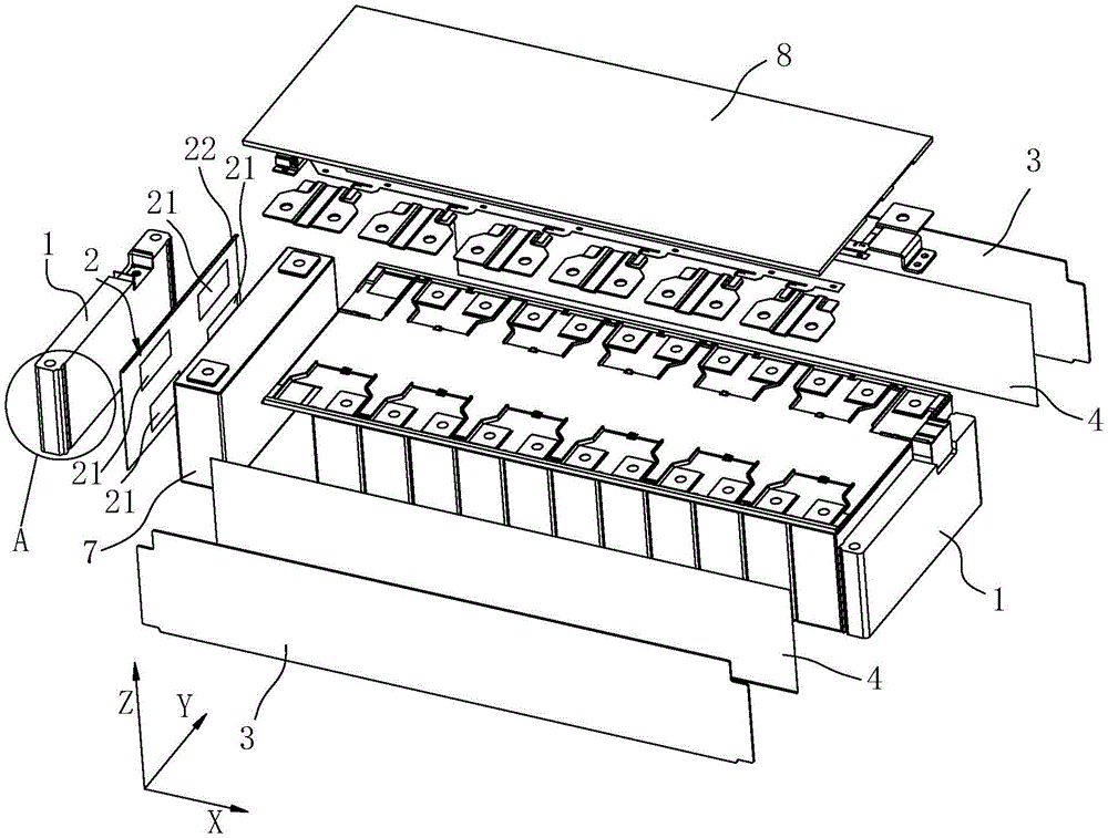
图1为实施例所述电池模组的分解图。FIG. 1 is an exploded view of the battery module according to the embodiment.
图2为图1中A处的放大图。FIG. 2 is an enlarged view of A in FIG. 1 .
图3为实施例所述电池模组的部分剖视图。FIG. 3 is a partial cross-sectional view of the battery module according to the embodiment.
图4为另一实施例所述第一绝缘片的结构示意图(图中未示出定位钩)。FIG. 4 is a schematic structural diagram of the first insulating sheet according to another embodiment (the positioning hook is not shown in the figure).
图5为再一实施例所述第一绝缘片的结构示意图(图中未示出定位钩)。FIG. 5 is a schematic structural diagram of the first insulating sheet according to still another embodiment (the positioning hook is not shown in the figure).
图中:In the picture:
1、端板;2、第一绝缘片;21、粘接孔;22、定位钩;3、侧板;4、第二绝缘片;5、第一凹槽;6、第二凹槽;7、电芯;8、顶板。1. End plate; 2. First insulating sheet; 21. Bonding hole; 22. Positioning hook; 3. Side plate; 4. Second insulating sheet; 5. First groove; 6. Second groove; 7 , Battery; 8, the top plate.
具体实施方式Detailed ways
为使本实用新型解决的技术问题、采用的技术方案和达到的技术效果更加清楚,下面将结合附图对本实用新型实施例的技术方案作进一步的详细描述,显然,所描述的实施例仅仅是本实用新型一部分实施例,而不是全部的实施例。基于本实用新型中的实施例,本领域技术人员在没有作出创造性劳动前提下所获得的所有其他实施例,都属于本实用新型保护的范围。In order to make the technical problems solved by the present invention, the technical solutions adopted and the technical effects achieved more clearly, the technical solutions of the embodiments of the present invention will be described in further detail below with reference to the accompanying drawings. Obviously, the described embodiments are only Some embodiments of the present invention, but not all embodiments. Based on the embodiments of the present invention, all other embodiments obtained by those skilled in the art without creative work fall within the protection scope of the present invention.
在本实用新型的描述中,除非另有明确的规定和限定,术语“相连”、“连接”、“固定”应做广义理解,例如,可以是固定连接,也可以是可拆卸连接,或成一体;可以是机械连接,也可以是电连接;可以是直接相连,也可以通过中间媒介间接相连,可以是两个元件内部的连通或两个元件的相互作用关系。对于本领域的普通技术人员而言,可以具体情况理解上述术语在本实用新型中的具体含义。In the description of the present invention, unless otherwise expressly specified and limited, the terms "connected", "connected" and "fixed" should be understood in a broad sense, for example, it may be a fixed connection, a detachable connection, or a fixed connection. It can be a mechanical connection or an electrical connection; it can be a direct connection or an indirect connection through an intermediate medium, and it can be an internal connection between two elements or an interaction relationship between the two elements. For those of ordinary skill in the art, the specific meanings of the above terms in the present invention can be understood in specific situations.
在本实用新型中,除非另有明确的规定和限定,第一特征在第二特征之“上”或之“下”可以包括第一和第二特征直接接触,也可以包括第一和第二特征不是直接接触而是通过它们之间的另外的特征接触。而且,第一特征在第二特征“之上”、“上方”和“上面”包括第一特征在第二特征正上方和斜上方,或仅仅表示第一特征水平高度高于第二特征。第一特征在第二特征“之下”、“下方”和“下面”包括第一特征在第二特征正下方和斜下方,或仅仅表示第一特征水平高度小于第二特征。In the present invention, unless otherwise expressly specified and limited, a first feature "on" or "under" a second feature may include the first and second features in direct contact, or may include the first and second features The features are not in direct contact but through additional features between them. Also, the first feature being "above", "over" and "above" the second feature includes the first feature being directly above and obliquely above the second feature, or simply means that the first feature is level higher than the second feature. The first feature is "below", "below" and "below" the second feature includes the first feature being directly below and diagonally below the second feature, or simply means that the first feature has a lower level than the second feature.
如图1至图5所示,其中,图1中,X方向表示电池模组长度方向,Y方向表示电池模组宽度方向,Z方向表示电池模组高度方向。本实用新型提供一种电池模组,包括外包围板以及电芯7,所述外包围板包括两个相对的侧板3、设置在两个所述侧板3之间的端板1以及设置端板1上端的顶板9,两个端板1沿着所述侧板3长度方向(即电池模组长度方向)间隔分布,所述侧板3和所述端板1共同围设形成容纳腔,所述电芯7设置在所述容纳腔中,所述端板1与所述电芯7之间设置有第一绝缘片2,所述第一绝缘片2贯穿开设有至少一个粘接孔21,所述粘接孔21内填充绝缘胶,所述第一绝缘片2通过所述绝缘胶分别与所述端板1和所述电芯7粘接。利用粘接孔21可以存储绝缘胶,通过粘接孔21内部的绝缘胶将第一绝缘片2牢固地粘接在端板1与电芯7之间。由于粘接孔21贯穿第一绝缘片2,一方面,可以在粘接孔21内存储较多的绝缘胶,增大绝缘胶的厚度,增强第一绝缘片2与端板1和电芯7之间的粘接力,降低第一绝缘片2从端板1和电芯7上脱离的风险;另一方面,在实际涂胶时,不需要在第一绝缘片2相对的两侧面涂满粘胶剂,仅仅是在粘接孔21内填充绝缘胶,节省了绝缘胶的使用量,以及缩短涂胶的时间,提升第一绝缘片2的组装效率。As shown in FIGS. 1 to 5 , in FIG. 1 , the X direction represents the length direction of the battery module, the Y direction represents the width direction of the battery module, and the Z direction represents the height direction of the battery module. The utility model provides a battery module, which includes an outer enclosure plate and a battery core 7 , the outer enclosure plate includes two
本实施例中,第一绝缘片2上间隔设置有四个所述粘接孔21。具体地,各所有的所述粘接孔21的面积之和与所述第一绝缘片2正对所述端板1一侧面的面积之比为:1/2~3/4。此种设计,在保证第一绝缘片2具有足够结构强度的基础上,也保证粘接孔21中可以填充足够量的绝缘胶,为第一绝缘片2与端板1以及电芯7之间提供足够的粘接力。在实际设计时,可以根据需要灵活设置粘接孔21的数量。In this embodiment, the
作为一种优选的实施例,参照图4,所述粘接孔21的孔壁呈波浪结构。或者,参照图5,所述粘接孔21的孔壁呈锯齿结构。将粘接孔21的孔壁设置为上述的结构,可以增加绝缘胶与粘接孔21的孔壁接触面积,使绝缘胶与对粘接孔21孔壁牢固粘接,降低绝缘胶从粘接孔21内溢胶的可能性。As a preferred embodiment, referring to FIG. 4 , the hole wall of the
当然在其他的实施例中,也可以将粘接孔21的孔壁设置为直边结构,在此并不对粘接孔21的孔壁作具体限制。Of course, in other embodiments, the hole wall of the
一实施例中,所述第一绝缘片2的上端朝向背离所述端板1的方向凸设有定位钩22,所述定位钩22与所述电芯7的顶部连接。定位钩22的设置,可将整个第一绝缘片2勾紧在电芯7的顶部,使第一绝缘片2被定位在电芯7上,实现对第一绝缘片2的定位,在组装第一绝缘片2时,可以先将第一绝缘片2的勾接在电芯7上,调整后好第一绝缘片2的具体位置时,在粘接孔21内填充绝缘胶,此设计,方便调整第一绝缘片2的位置以及提升了粘接第一绝缘片2的便捷性。In one embodiment, a
在对第一绝缘片2定位的过程中,为了防止定位钩22从电芯7上脱离,在本实施例中,所述定位钩22靠近所述电芯7的侧面设置有双面胶,所述定位钩22通过所述双面胶与所述电芯7连接。双面胶层的设置,可以将定位钩22与电芯7的上表面定位,在粘接孔21内填充绝缘胶时不需要手扶第一绝缘片2。此外,由于定位钩22通过双面胶层电芯粘接,需要调整第一绝缘片2在电芯7上的位置时,可将定位钩22从电芯7的顶部撕下,使双面胶层从电芯的顶部脱离,然后再将定位钩22在电芯7上移动,方便调整第一绝缘片2在电芯7上的位置。In the process of positioning the first insulating
通常端板1和侧板3是通过焊接连接,在粘接孔21内填充绝缘胶的过程中,难以避免绝缘胶从粘接孔21中溢出到第一绝缘片2的表面,所述端板1靠近所述第一绝缘片2的一侧间隔凹设有两个第一凹槽5,所述第一凹槽5沿所述端板1高度方向(即电池模组高度方向)延伸,所述粘接孔21位于两个所述第一凹槽5之间,所述端板1靠近所述第一绝缘片2的一侧分别凹设有两个第一凹槽5,所述第一凹槽5沿所述端板高度方向(即电池模组高度方向)延伸,所述粘接孔21位于两个所述第一凹槽5之间。通过设置第一凹槽5,粘接可以存储从粘接孔21中溢出的绝缘胶,避免绝缘胶流至端板1与侧板3的焊接区域。Usually the end plate 1 and the
具体地,所述第一凹槽5分别连通所述端板1的上端和下端。此种结构的第一凹槽5,在重力的作用下会使得第一凹槽5内的绝缘胶沿着第一凹槽5向下流动,进而将进而流至外包围板的外壁,减少绝缘胶在第一凹槽5内部的积累量。Specifically, the
当然,在另外的实施例中,也可以将第一凹槽5未贯穿端板1的上端和下端设置。Of course, in other embodiments, the
本实施例中,所述端板1靠近第一绝缘片2一侧面间隔设置有两个第二凹槽6,所述第一凹槽5位于所述粘接孔21与所述第二凹槽6之间,所述侧板3与所述电芯7之间设置有第二绝缘片4,所述第二绝缘片4端部插至所述第二凹槽6内。第二凹槽6可以容纳第二绝缘片4超出电芯7端面的部分,方便对第二绝缘片4的定位,此外,第二凹槽6也可以存储第一绝缘片2的溢胶,杜绝第一绝缘片2上的绝缘胶溢流至端板1与侧板3焊接区域。In this embodiment, two
本实施例中,所述第一绝缘片2靠近所述侧板3的两端分别所述第二绝缘片4靠近所述电芯7的一侧面抵接。In this embodiment, two ends of the first insulating
于本文的描述中,需要理解的是,术语“上”、“下”、“左”、“右”、等方位或位置关系为基于附图所示的方位或位置关系,仅是为了便于描述和简化操作,而不是指示或暗示所指的装置或元件必须具有特定的方位、以特定的方位构造和操作,因此不能理解为对本实用新型的限制。此外,术语“第一”、“第二”仅仅用于在描述上加以区分,并没有特殊的含义。In the description herein, it should be understood that the terms "up", "down", "left", "right", etc. are based on the orientation or positional relationship shown in the accompanying drawings, and are only for the convenience of description. and simplifies operation, rather than indicating or implying that the device or element referred to must have a particular orientation, be constructed and operate in a particular orientation, and therefore should not be construed as a limitation of the present invention. In addition, the terms "first" and "second" are only used for distinction in description, and have no special meaning.
在本说明书的描述中,参考术语“一实施例”、“示例”等的描述意指结合该实施例或示例描述的具体特征、结构、材料或者特点包含于本实用新型的至少一个实施例或示例中。在本说明书中,对上述术语的示意性表述不一定指的是相同的实施例或示例。In the description of this specification, reference to the description of the terms "an embodiment", "example" etc. means that a particular feature, structure, material or characteristic described in connection with the embodiment or example is included in at least one embodiment or example. In this specification, schematic representations of the above terms do not necessarily refer to the same embodiment or example.
此外,应当理解,虽然本说明书按照实施方式加以描述,但并非每个实施方式仅包含一个独立的技术方案,说明书的这种叙述方式仅仅是为清楚起见,本领域技术人员应当将说明书作为一个整体,各实施例中的技术方案也可以适当组合,形成本领域技术人员可以理解的其他实施方式。In addition, it should be understood that although this specification is described in terms of embodiments, not each embodiment only includes an independent technical solution, and this description in the specification is only for the sake of clarity, and those skilled in the art should take the specification as a whole , the technical solutions in each embodiment can also be appropriately combined to form other implementations that can be understood by those skilled in the art.
以上结合具体实施例描述了本实用新型的技术原理。这些描述只是为了解释本实用新型的原理,而不能以任何方式解释为对本实用新型保护范围的限制。基于此处的解释,本领域的技术人员不需要付出创造性的劳动即可联想到本实用新型的其它具体实施方式,这些方式都将落入本实用新型的保护范围之内。The technical principle of the present invention has been described above with reference to the specific embodiments. These descriptions are only for explaining the principle of the present invention, and should not be construed as limiting the protection scope of the present invention in any way. Based on the explanations herein, those skilled in the art can think of other specific embodiments of the present invention without creative efforts, and these methods will all fall within the protection scope of the present invention.
Claims (9)
Priority Applications (1)
| Application Number | Priority Date | Filing Date | Title |
|---|---|---|---|
| CN201922166287.6U CN211238404U (en) | 2019-12-05 | 2019-12-05 | Battery module |
Applications Claiming Priority (1)
| Application Number | Priority Date | Filing Date | Title |
|---|---|---|---|
| CN201922166287.6U CN211238404U (en) | 2019-12-05 | 2019-12-05 | Battery module |
Publications (1)
| Publication Number | Publication Date |
|---|---|
| CN211238404U true CN211238404U (en) | 2020-08-11 |
Family
ID=71920973
Family Applications (1)
| Application Number | Title | Priority Date | Filing Date |
|---|---|---|---|
| CN201922166287.6U Active CN211238404U (en) | 2019-12-05 | 2019-12-05 | Battery module |
Country Status (1)
| Country | Link |
|---|---|
| CN (1) | CN211238404U (en) |
Cited By (2)
| Publication number | Priority date | Publication date | Assignee | Title |
|---|---|---|---|---|
| EP4145605A1 (en) * | 2021-09-07 | 2023-03-08 | Samsung SDI Co., Ltd. | Rechargeable battery module |
| WO2025102636A1 (en) * | 2023-11-13 | 2025-05-22 | 宁德时代新能源科技股份有限公司 | Battery module, battery and electrical apparatus |
-
2019
- 2019-12-05 CN CN201922166287.6U patent/CN211238404U/en active Active
Cited By (5)
| Publication number | Priority date | Publication date | Assignee | Title |
|---|---|---|---|---|
| EP4145605A1 (en) * | 2021-09-07 | 2023-03-08 | Samsung SDI Co., Ltd. | Rechargeable battery module |
| CN115775950A (en) * | 2021-09-07 | 2023-03-10 | 三星Sdi株式会社 | Rechargeable battery module |
| US12489163B2 (en) | 2021-09-07 | 2025-12-02 | Samsung Sdi Co., Ltd. | Rechargeable battery module |
| CN115775950B (en) * | 2021-09-07 | 2026-07-14 | 三星Sdi株式会社 | Rechargeable battery module |
| WO2025102636A1 (en) * | 2023-11-13 | 2025-05-22 | 宁德时代新能源科技股份有限公司 | Battery module, battery and electrical apparatus |
Similar Documents
| Publication | Publication Date | Title |
|---|---|---|
| CN209447881U (en) | A kind of battery modules | |
| CN111799429B (en) | Pouch battery and method for assembling pouch battery | |
| CN217158351U (en) | A soft pack battery module | |
| CN219040683U (en) | a battery | |
| CN114725596B (en) | Battery cell fixing structure, battery pack and battery cell fixing method | |
| CN219476880U (en) | a battery device | |
| CN118448795A (en) | CTP battery box and CTP battery system | |
| CN103262289A (en) | Battery | |
| CN219051933U (en) | Auxiliary structure for gluing, battery module and battery pack | |
| CN217306613U (en) | A Mylar membrane structure and lithium battery | |
| CN216250941U (en) | A battery module and its battery pack based on insulating adhesive bonding | |
| CN118398981A (en) | Battery module, electric equipment and glue filling method | |
| CN207818732U (en) | Battery modules | |
| CN219534555U (en) | Electrode plate and battery | |
| CN211980699U (en) | Battery end plate and battery module | |
| CN210805831U (en) | Square battery module with novel upper cover and side plate connecting structure | |
| CN220400844U (en) | Module connecting row and battery box | |
| CN215507586U (en) | Battery row bonding assembly and battery module | |
| CN219123436U (en) | Battery insulating film and power battery | |
| CN217444526U (en) | Curb plate, CTP module and battery package system | |
| CN219163546U (en) | Soft packet of lithium cell module of high protection level | |
| CN219759723U (en) | Liquid cooling plate and battery pack | |
| CN209860077U (en) | Lithium battery assembly structure | |
| CN217426911U (en) | Battery module and power battery | |
| CN218602516U (en) | Battery core and battery |
Legal Events
| Date | Code | Title | Description |
|---|---|---|---|
| GR01 | Patent grant | ||
| GR01 | Patent grant |