CN211237851U - A high-power medium-wave load resistor cavity - Google Patents
A high-power medium-wave load resistor cavity Download PDFInfo
- Publication number
- CN211237851U CN211237851U CN202020300711.1U CN202020300711U CN211237851U CN 211237851 U CN211237851 U CN 211237851U CN 202020300711 U CN202020300711 U CN 202020300711U CN 211237851 U CN211237851 U CN 211237851U
- Authority
- CN
- China
- Prior art keywords
- fixedly connected
- box
- plate
- wave load
- power medium
- Prior art date
- Legal status (The legal status is an assumption and is not a legal conclusion. Google has not performed a legal analysis and makes no representation as to the accuracy of the status listed.)
- Expired - Fee Related
Links
Images


Landscapes
- Cooling Or The Like Of Electrical Apparatus (AREA)
Abstract
本实用新型公开了一种大功率中波负载电阻腔体,包括箱体,所述箱体的内腔固定连接有竖板,所述竖板的右侧固定连接有横板,所述横板的右侧与箱体的内壁固定连接,所述横板的顶部固定连接有电阻本体,所述箱体内腔左侧的底部和顶部均固定连接有电机,所述电机转轴的右端通过连接块固定连接有扇叶,所述箱体的左侧固定连接有过滤箱,所述过滤箱内腔的顶部和底部均固定连接有支撑板。本实用新型具备具有散热功能且可对空气进行过滤的优点,解决了现有的大功率中波负载电阻腔体,在使用过程中,由于结构单一,无法对电阻进行有效的散热,导致电阻温度容易过高,从而造成损坏,降低了电阻使用寿命的问题。
The utility model discloses a high-power medium-wave load resistance cavity, comprising a box body, an inner cavity of the box body is fixedly connected with a vertical plate, the right side of the vertical plate is fixedly connected with a horizontal plate, and the horizontal plate is fixedly connected with the horizontal plate. The right side of the box is fixedly connected to the inner wall of the box, the top of the horizontal plate is fixedly connected to the resistor body, the bottom and top of the left side of the box are fixedly connected to the motor, and the right end of the motor shaft is fixed by the connecting block. A fan blade is connected, a filter box is fixedly connected to the left side of the box body, and a support plate is fixedly connected to the top and bottom of the inner cavity of the filter box. The utility model has the advantages of having a heat dissipation function and can filter the air, and solves the problem of the existing high-power medium-wave load resistance cavity. During the use process, due to the single structure, the resistance cannot be effectively dissipated, resulting in resistance temperature. It is easy to be too high, causing damage and reducing the service life of the resistor.
Description
技术领域technical field
本实用新型涉及负载电阻技术领域,具体为一种大功率中波负载电阻腔体。The utility model relates to the technical field of load resistance, in particular to a high-power medium-wave load resistance cavity.
背景技术Background technique
电阻器在日常生活中一般直接称为电阻,是一个限流元件,将电阻接在电路中后,电阻器的阻值是固定的一般是两个引脚,它可限制通过它所连支路的电流大小,阻值不能改变的称为固定电阻器,阻值可变的称为电位器或可变电阻器。Resistors are generally called resistors in daily life. They are current-limiting components. After connecting the resistors in the circuit, the resistance of the resistors is fixed. Generally, there are two pins, which can limit the branch through which it is connected. The size of the current, the resistance value cannot be changed is called a fixed resistor, and the resistance value is variable is called a potentiometer or a variable resistor.
现有的大功率中波负载电阻腔体,在使用过程中,由于结构单一,无法对电阻进行有效的散热,导致电阻温度容易过高,从而造成损坏,降低了电阻的使用寿命。In the existing high-power medium-wave load resistance cavity, during use, due to the single structure, the resistance cannot be effectively dissipated, resulting in the resistance temperature being easily too high, resulting in damage and reducing the service life of the resistance.
实用新型内容Utility model content
本实用新型的目的在于提供一种大功率中波负载电阻腔体,具备具有散热功能且可对空气进行过滤的优点,解决了现有的大功率中波负载电阻腔体,在使用过程中,由于结构单一,无法对电阻进行有效的散热,导致电阻温度容易过高,从而造成损坏,降低了电阻使用寿命的问题。The purpose of the utility model is to provide a high-power medium-wave load resistance cavity, which has the advantages of having a heat dissipation function and can filter the air, and solves the problem of the existing high-power medium-wave load resistance cavity. Due to the single structure, the resistor cannot be effectively dissipated, resulting in the resistor temperature being easily too high, resulting in damage and reducing the service life of the resistor.
为实现上述目的,本实用新型提供如下技术方案:一种大功率中波负载电阻腔体,包括箱体,所述箱体的内腔固定连接有竖板,所述竖板的右侧固定连接有横板,所述横板的右侧与箱体的内壁固定连接,所述横板的顶部固定连接有电阻本体,所述箱体内腔左侧的底部和顶部均固定连接有电机,所述电机转轴的右端通过连接块固定连接有扇叶,所述箱体的左侧固定连接有过滤箱,所述过滤箱内腔的顶部和底部均固定连接有支撑板,所述支撑板相对的一侧均开设有密封槽,所述密封槽相对的一侧固定连接有过滤板,所述过滤箱的左侧开设有进风孔,所述箱体的左侧开设有第一通风孔,所述竖板的左侧开设有第二通风孔,所述箱体的右侧开设有排风孔,所述箱体前侧的右侧通过铰链活动连接有盖板,所述盖板位于电阻本体的前侧。In order to achieve the above purpose, the utility model provides the following technical solutions: a high-power medium wave load resistance cavity, including a box body, the inner cavity of the box body is fixedly connected with a vertical plate, and the right side of the vertical plate is fixedly connected There is a horizontal plate, the right side of the horizontal plate is fixedly connected with the inner wall of the box body, the top of the horizontal plate is fixedly connected with a resistor body, and the bottom and top of the left side of the box inner cavity are fixedly connected with a motor. A fan blade is fixedly connected to the right end of the motor shaft through a connecting block, a filter box is fixedly connected to the left side of the box body, and a support plate is fixedly connected to the top and bottom of the inner cavity of the filter box. The sides are provided with sealing grooves, the opposite side of the sealing grooves is fixedly connected with a filter plate, the left side of the filter box is provided with an air inlet hole, the left side of the box body is provided with a first ventilation hole, the The left side of the vertical plate is provided with a second ventilation hole, the right side of the box body is provided with an exhaust hole, and the right side of the front side of the box body is movably connected with a cover plate through a hinge, and the cover plate is located on the side of the resistor body. front side.
优选的,所述横板的数量为四个,所述横板之间等距离排列。Preferably, the number of the horizontal plates is four, and the horizontal plates are arranged at equal distances.
优选的,所述盖板前侧左侧的顶部和底部均通过转轴活动连接有卡扣,所述箱体前侧的顶部和顶部均固定连接有与卡扣相适配的卡块,所述卡扣的左侧与卡块卡接。Preferably, the top and bottom of the left side of the front side of the cover plate are movably connected with buckles through rotating shafts, and the top and the top of the front side of the box are fixedly connected with clips adapted to the buckles. The left side of the buckle is connected with the card block.
优选的,所述过滤箱的前侧固定连接有密封板,所述密封板前侧的四角均贯穿设置有螺栓,螺栓的后端依次贯穿密封板和过滤箱并与过滤箱螺纹连接。Preferably, a sealing plate is fixedly connected to the front side of the filter box, four corners of the front side of the sealing plate are provided with bolts, and the rear ends of the bolts sequentially penetrate the sealing plate and the filter box and are threadedly connected to the filter box.
优选的,所述箱体底部的四角均固定连接有支撑块,支撑块的底部设置有橡胶垫。Preferably, the four corners of the bottom of the box are fixedly connected with support blocks, and the bottom of the support blocks is provided with rubber pads.
优选的,所述箱体的前侧固定连接有控制器,所述控制器与电机电性连接。Preferably, a controller is fixedly connected to the front side of the box, and the controller is electrically connected to the motor.
与现有技术相比,本实用新型的有益效果如下:Compared with the prior art, the beneficial effects of the present utility model are as follows:
1、本实用新型通过箱体、竖板、横板、电阻本体、电机、扇叶、过滤箱、支撑板、密封槽、过滤板、进风孔、第一通风孔、第二通风孔和排风孔的配合,具备具有散热功能且可对空气进行过滤的优点,解决了现有的大功率中波负载电阻腔体,在使用过程中,由于结构单一,无法对电阻进行有效的散热,导致电阻温度容易过高,从而造成损坏,降低了电阻使用寿命的问题。1. The utility model passes through the box, the vertical plate, the horizontal plate, the resistor body, the motor, the fan blade, the filter box, the support plate, the sealing groove, the filter plate, the air inlet hole, the first ventilation hole, the second ventilation hole and the row. The combination of the air holes has the advantages of having a heat dissipation function and can filter the air, which solves the problem of the existing high-power medium-wave load resistance cavity. During the use process, due to the single structure, the resistance cannot be effectively dissipated, resulting in The resistance temperature is easy to be too high, causing damage and reducing the service life of the resistance.
2、本实用新型通过设置横板,便于对电阻本体进行稳定的固定,通过设置电机和扇叶,可以对电阻本体进行有效的散热,增加电阻本体的使用寿命,通过设置支撑板和密封槽,可以对过滤板进行密封固定,通过设置过滤板,可以对空气进行过滤,防止杂质进入箱体,通过设置进风孔和排风孔,便于空气的流通,通过设置盖板、卡扣和卡块,便于对电阻本体进行拆卸更换,通过设置密封板,便于对过滤板进行拆卸清洗。2. The utility model is convenient to stably fix the resistor body by setting the horizontal plate. By setting the motor and the fan blade, the resistor body can be effectively dissipated and the service life of the resistor body can be increased. By setting the support plate and the sealing groove, The filter plate can be sealed and fixed. By setting the filter plate, the air can be filtered to prevent impurities from entering the box. By setting the air inlet and exhaust holes, it is convenient for air circulation. , it is convenient to disassemble and replace the resistor body, and by setting the sealing plate, it is convenient to disassemble and clean the filter plate.
附图说明Description of drawings
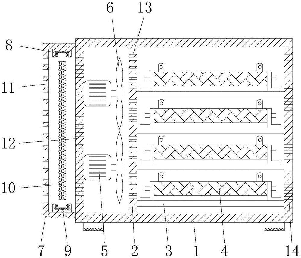
图1为本实用新型结构剖视示意图;Fig. 1 is the structural sectional schematic diagram of the utility model;
图2为本实用新型结构正视示意图;Fig. 2 is the front view schematic diagram of the structure of the utility model;
图3为本实用新型结构右视示意图。FIG. 3 is a schematic diagram of a right side view of the structure of the utility model.
图中:1箱体、2竖板、3横板、4电阻本体、5电机、6扇叶、7过滤箱、8支撑板、9密封槽、10过滤板、11进风孔、12第一通风孔、13第二通风孔、14排风孔、15盖板、16卡扣、17卡块、18密封板、19控制器。In the picture: 1 box, 2 vertical plates, 3 horizontal plates, 4 resistor bodies, 5 motors, 6 fan blades, 7 filter boxes, 8 support plates, 9 seal grooves, 10 filter plates, 11 air inlet holes, 12 first Ventilation holes, 13 second ventilation holes, 14 exhaust holes, 15 cover plates, 16 snaps, 17 clips, 18 sealing plates, 19 controllers.
具体实施方式Detailed ways
下面将结合本实用新型实施例中的附图,对本实用新型实施例中的技术方案进行清楚、完整地描述,显然,所描述的实施例仅仅是本实用新型一部分实施例,而不是全部的实施例。基于本实用新型中的实施例,本领域普通技术人员在没有做出创造性劳动前提下所获得的所有其他实施例,都属于本实用新型保护的范围。The technical solutions in the embodiments of the present utility model will be clearly and completely described below with reference to the accompanying drawings in the embodiments of the present utility model. Obviously, the described embodiments are only a part of the embodiments of the present utility model, rather than all the implementations. example. Based on the embodiments of the present invention, all other embodiments obtained by those of ordinary skill in the art without creative work fall within the protection scope of the present invention.
在实用新型的描述中,需要说明的是,术语“上”、“下”、“内”、“外”“前端”、“后端”、“两端”、“一端”、“另一端”等指示的方位或位置关系为基于附图所示的方位或位置关系,仅是为了便于描述本实用新型和简化描述,而不是指示或暗示所指的装置或元件必须具有特定的方位、以特定的方位构造和操作,因此不能理解为对本实用新型的限制。此外,术语“第一”、“第二”仅用于描述目的,而不能理解为指示或暗示相对重要性。In the description of the utility model, it should be noted that the terms "upper", "lower", "inner", "outer", "front end", "rear end", "two ends", "one end" and "the other end" The orientation or positional relationship indicated by etc. is based on the orientation or positional relationship shown in the accompanying drawings, which is only for the convenience of describing the present invention and simplifying the description, rather than indicating or implying that the referred device or element must have a specific orientation, with a specific orientation. Therefore, it should not be construed as a limitation on the present invention. Furthermore, the terms "first" and "second" are used for descriptive purposes only and should not be construed to indicate or imply relative importance.
在实用新型的描述中,需要说明的是,除非另有明确的规定和限定,术语“安装”、“设置有”、“连接”等,应做广义理解,例如“连接”,可以是固定连接,也可以是可拆卸连接,或一体地连接;可以是机械连接,也可以是电连接;可以是直接相连,也可以通过中间媒介间接相连,可以是两个元件内部的连通。对于本领域的普通技术人员而言,可以具体情况理解上述术语在本实用新型中的具体含义。In the description of the utility model, it should be noted that, unless otherwise expressly specified and limited, the terms "installed", "provided with", "connected", etc., should be understood in a broad sense, for example, "connected" may be a fixed connection It can also be a detachable connection or an integral connection; it can be a mechanical connection or an electrical connection; it can be a direct connection, or an indirect connection through an intermediate medium, or the internal communication between the two components. For those of ordinary skill in the art, the specific meanings of the above terms in the present invention can be understood in specific situations.
本实用新型的箱体1、竖板2、横板3、电阻本体4、电机5、扇叶6、过滤箱7、支撑板8、密封槽9、过滤板10、进风孔11、第一通风孔12、第二通风孔13、排风孔14、盖板15、卡扣16、卡块17、密封板18和控制器19部件均为通用标准件或本领域技术人员知晓的部件,其结构和原理都为本技术人员均可通过技术手册得知或通过常规实验方法获知。The
请参阅图1-3,一种大功率中波负载电阻腔体,包括箱体1,箱体1底部的四角均固定连接有支撑块,支撑块的底部设置有橡胶垫,箱体1的前侧固定连接有控制器19,控制器19与电机5电性连接,箱体1的内腔固定连接有竖板2,竖板2的右侧固定连接有横板3,横板3的数量为四个,横板3之间等距离排列,通过设置横板3,便于对电阻本体4进行稳定的固定,横板3的右侧与箱体1的内壁固定连接,横板3的顶部固定连接有电阻本体4,箱体1内腔左侧的底部和顶部均固定连接有电机5,电机5转轴的右端通过连接块固定连接有扇叶6,通过设置电机5和扇叶6,可以对电阻本体4进行有效的散热,增加电阻本体4的使用寿命,箱体1的左侧固定连接有过滤箱7,过滤箱7的前侧固定连接有密封板18,密封板18前侧的四角均贯穿设置有螺栓,螺栓的后端依次贯穿密封板18和过滤箱7并与过滤箱7螺纹连接,通过设置密封板18,便于对过滤板10进行拆卸清洗,过滤箱7内腔的顶部和底部均固定连接有支撑板8,支撑板8相对的一侧均开设有密封槽9,通过设置支撑板8和密封槽9,可以对过滤板10进行密封固定,密封槽9相对的一侧固定连接有过滤板10,通过设置过滤板10,可以对空气进行过滤,防止杂质进入箱体1,过滤箱7的左侧开设有进风孔11,箱体1的左侧开设有第一通风孔12,竖板2的左侧开设有第二通风孔13,箱体1的右侧开设有排风孔14,通过设置进风孔11和排风孔14,便于空气的流通,箱体1前侧的右侧通过铰链活动连接有盖板15,盖板15前侧左侧的顶部和底部均通过转轴活动连接有卡扣16,箱体1前侧的顶部和顶部均固定连接有与卡扣16相适配的卡块17,卡扣16的左侧与卡块17卡接,通过设置盖板15、卡扣16和卡块17,便于对电阻本体4进行拆卸更换,盖板15位于电阻本体4的前侧,通过箱体1、竖板2、横板3、电阻本体4、电机5、扇叶6、过滤箱7、支撑板8、密封槽9、过滤板10、进风孔11、第一通风孔12、第二通风孔13和排风孔14的配合,具备具有散热功能且可对空气进行过滤的优点,解决了现有的大功率中波负载电阻腔体,在使用过程中,由于结构单一,无法对电阻进行有效的散热,导致电阻温度容易过高,从而造成损坏,降低了电阻使用寿命的问题。Please refer to Figure 1-3, a high-power medium-wave load resistor cavity, including a
使用时,接入220v工业用电,通过控制器19控制电机5运转,电机5转轴带动扇叶6旋转,外界空气在扇叶6的作用下通过进风孔11进入到过滤箱7的内腔,过滤板10对空气中含有的粉尘和杂质进行过滤,过滤后的空气通过第一通风孔12和第二通风孔13进入到箱体1的内腔,空气对电阻本体4进行吹风散热,热气通过排风孔14排出箱体1的外部。When in use, connect to 220v industrial electricity, control the
综上所述:该大功率中波负载电阻腔体,通过箱体1、竖板2、横板3、电阻本体4、电机5、扇叶6、过滤箱7、支撑板8、密封槽9、过滤板10、进风孔11、第一通风孔12、第二通风孔13和排风孔14的配合,解决了现有的大功率中波负载电阻腔体,在使用过程中,由于结构单一,无法对电阻进行有效的散热,导致电阻温度容易过高,从而造成损坏,降低了电阻使用寿命的问题。In summary: the high-power medium-wave load resistor cavity passes through the
尽管已经示出和描述了本实用新型的实施例,对于本领域的普通技术人员而言,可以理解在不脱离本实用新型的原理和精神的情况下可以对这些实施例进行多种变化、修改、替换和变型,本实用新型的范围由所附权利要求及其等同物限定。Although the embodiments of the present invention have been shown and described, it will be understood by those skilled in the art that various changes and modifications can be made to these embodiments without departing from the principles and spirit of the present invention , alternatives and modifications, the scope of the present invention is defined by the appended claims and their equivalents.
Claims (6)
Priority Applications (1)
| Application Number | Priority Date | Filing Date | Title |
|---|---|---|---|
| CN202020300711.1U CN211237851U (en) | 2020-03-12 | 2020-03-12 | A high-power medium-wave load resistor cavity |
Applications Claiming Priority (1)
| Application Number | Priority Date | Filing Date | Title |
|---|---|---|---|
| CN202020300711.1U CN211237851U (en) | 2020-03-12 | 2020-03-12 | A high-power medium-wave load resistor cavity |
Publications (1)
| Publication Number | Publication Date |
|---|---|
| CN211237851U true CN211237851U (en) | 2020-08-11 |
Family
ID=71920277
Family Applications (1)
| Application Number | Title | Priority Date | Filing Date |
|---|---|---|---|
| CN202020300711.1U Expired - Fee Related CN211237851U (en) | 2020-03-12 | 2020-03-12 | A high-power medium-wave load resistor cavity |
Country Status (1)
| Country | Link |
|---|---|
| CN (1) | CN211237851U (en) |
Cited By (1)
| Publication number | Priority date | Publication date | Assignee | Title |
|---|---|---|---|---|
| CN119993659A (en) * | 2024-12-31 | 2025-05-13 | 广东福德电子有限公司 | A high performance heat dissipation load unit |
-
2020
- 2020-03-12 CN CN202020300711.1U patent/CN211237851U/en not_active Expired - Fee Related
Cited By (1)
| Publication number | Priority date | Publication date | Assignee | Title |
|---|---|---|---|---|
| CN119993659A (en) * | 2024-12-31 | 2025-05-13 | 广东福德电子有限公司 | A high performance heat dissipation load unit |
Similar Documents
| Publication | Publication Date | Title |
|---|---|---|
| WO2020199343A1 (en) | Dustproof heat dissipation cover of brushless electric motor | |
| CN206149307U (en) | A Router Convenient for Heat Dissipation and Dust Removal | |
| CN209563109U (en) | A cooling device for electrical and electronic equipment | |
| CN218276358U (en) | lift motor | |
| CN211210356U (en) | Novel load extrinsic cycle heat dissipation device | |
| CN111029951A (en) | A power module that is easy to dissipate heat and suitable for high power or high current | |
| CN216204315U (en) | Air energy heat pump with heat cycle | |
| CN213305269U (en) | Frequency converter with good dustproof performance | |
| CN209276573U (en) | An air cooling fan for heat treatment | |
| CN212230929U (en) | Air-cooled electric control cabinet | |
| CN211788519U (en) | Low-voltage welding transformer | |
| CN213176129U (en) | Dust protected blower motor | |
| CN209731922U (en) | A dust-proof and heat-dissipating device for an electrical control box | |
| CN218163368U (en) | Frequency converter heat dissipation shell and frequency converter comprising same | |
| CN221467219U (en) | Overheat protection structure of photovoltaic block terminal wiring | |
| CN221670277U (en) | A heat dissipation structure of industrial frequency inverter | |
| CN222052429U (en) | A distribution box with good use stability | |
| CN222214833U (en) | Power cabinet with dustproof function | |
| CN220474491U (en) | Capacitor with heat dissipation function | |
| CN206042665U (en) | An Isolation Transmitter with Rapid Heat Dissipation Function | |
| CN217545364U (en) | Power equipment protection device | |
| CN216312477U (en) | A power substation with good explosion-proof effect | |
| CN220042778U (en) | Operation control cabinet | |
| CN209343290U (en) | A kind of circumscribed auxiliary radiating device for computer | |
| CN217656237U (en) | Switch board with dustproof mechanism |
Legal Events
| Date | Code | Title | Description |
|---|---|---|---|
| GR01 | Patent grant | ||
| GR01 | Patent grant | ||
| CF01 | Termination of patent right due to non-payment of annual fee | ||
| CF01 | Termination of patent right due to non-payment of annual fee |
Granted publication date: 20200811 |