CN211236775U - computer optical drive mount - Google Patents
computer optical drive mount Download PDFInfo
- Publication number
- CN211236775U CN211236775U CN201920338769.2U CN201920338769U CN211236775U CN 211236775 U CN211236775 U CN 211236775U CN 201920338769 U CN201920338769 U CN 201920338769U CN 211236775 U CN211236775 U CN 211236775U
- Authority
- CN
- China
- Prior art keywords
- optical drive
- rod
- sliding seat
- thrust
- fixing device
- Prior art date
- Legal status (The legal status is an assumption and is not a legal conclusion. Google has not performed a legal analysis and makes no representation as to the accuracy of the status listed.)
- Active
Links
Images


Landscapes
- Holding Or Fastening Of Disk On Rotational Shaft (AREA)
Abstract
本实用新型公开了一种计算机光驱固定装置,包括用于放置光驱的支撑板和用于对光驱施加夹紧力的夹持机构,夹持机构包括可移动的设置于支撑板上的滑动座、设置于滑动座上的锁止杆和用于对滑动座施加使其移动的弹性作用力的推力组件,光驱具有让锁止杆插入的锁止槽。本实用新型的计算机光驱固定装置,避免了光驱采用多螺钉固定的模式,在光驱固定过程中简单高效和快速便捷,省时省力,降低了光驱安装的工作量,不影响光驱拆卸清灰,保障了光驱长时间正常使用。
The utility model discloses a computer optical drive fixing device, comprising a support plate for placing the optical drive and a clamping mechanism for applying a clamping force to the optical drive. The clamping mechanism comprises a movable sliding seat arranged on the support plate, A locking rod is arranged on the sliding seat and a thrust component is used to exert an elastic force to move the sliding seat, and the optical drive has a locking groove into which the locking rod is inserted. The computer optical drive fixing device of the utility model avoids the multi-screw fixing mode of the optical drive, is simple, efficient, fast and convenient in the fixing process of the optical drive, saves time and labor, reduces the workload of the installation of the optical drive, does not affect the disassembly and cleaning of the optical drive, and ensures the The optical drive has been used normally for a long time.
Description
技术领域technical field
本实用新型属于计算机技术领域,具体地说,本实用新型涉及一种计算机光驱固定装置。The utility model belongs to the technical field of computers, in particular, the utility model relates to a fixing device for a computer optical drive.
背景技术Background technique
光驱是电脑用来读写光碟内容的机器,也是在台式机和笔记本便携式电脑里比较常见的一个部件,随着多媒体的应用越来越广泛,使得光驱在计算机诸多配件中已经成为标准配置,光驱可分为CD-ROM驱动器、DVD光驱(DVD-ROM)、康宝(COMBO)、蓝光光驱(BD-ROM)和刻录机等。CD-ROM is a machine used by computers to read and write CD-ROM content. It is also a common component in desktop and notebook computers. With the increasing application of multimedia, CD-ROM has become a standard configuration in many computer accessories. Can be divided into CD-ROM drives, DVD drives (DVD-ROM), combo (COMBO), Blu-ray drives (BD-ROM) and recorders.
现有的光驱安装在电脑上大多采用螺钉固定,需要在光驱外壳上开设与螺钉相匹配的螺钉孔,多个螺钉固定过程繁琐不便,费时费力,增加了光驱安装的工作量,当螺钉损坏的时候,会影响光驱拆卸清灰,不利于光驱长时间使用,此外,光驱工作的时候问的较高,传统的机箱没有专门对光驱散热的机构,影响光驱的正常使用,降低了光驱的使用寿命。Most of the existing optical drives are installed on the computer with screws, and screw holes matching the screws need to be opened on the optical drive casing. The process of fixing multiple screws is cumbersome and inconvenient, time-consuming and laborious, and increases the workload of the optical drive installation. At times, it will affect the removal and cleaning of the optical drive, which is not conducive to the long-term use of the optical drive. In addition, when the optical drive is working, the problem is high. The traditional chassis does not have a special mechanism for cooling the optical drive, which affects the normal use of the optical drive and reduces the service life of the optical drive. .
实用新型内容Utility model content
本实用新型旨在至少解决现有技术中存在的技术问题之一。为此,本实用新型提供一种计算机光驱固定装置,目的是方便光驱的安装。The utility model aims to solve at least one of the technical problems existing in the prior art. Therefore, the utility model provides a fixing device for a computer optical drive, which aims to facilitate the installation of the optical drive.
为了实现上述目的,本实用新型采取的技术方案为:计算机光驱固定装置,包括用于放置光驱的支撑板和用于对光驱施加夹紧力的夹持机构,夹持机构包括可移动的设置于支撑板上的滑动座、设置于滑动座上的锁止杆和用于对滑动座施加使其移动的弹性作用力的推力组件,光驱具有让锁止杆插入的锁止槽。In order to achieve the above purpose, the technical solution adopted by the present invention is: a computer optical drive fixing device, comprising a support plate for placing the optical drive and a clamping mechanism for applying a clamping force to the optical drive, and the clamping mechanism includes a movable set on the A sliding seat on the support plate, a locking rod arranged on the sliding seat, and a thrust assembly for exerting elastic force to move the sliding seat, and the optical drive has a locking groove into which the locking rod is inserted.
所述推力组件包括导向杆、可移动的设置于导向杆中且与所述滑动座连接的推力杆和设置于导向杆中且对推力杆施加弹性作用力的第一弹簧,导向杆为内部中空的结构且导向杆位于所述支撑板的上方。The thrust assembly includes a guide rod, a movable thrust rod disposed in the guide rod and connected with the sliding seat, and a first spring disposed in the guide rod and exerting an elastic force on the thrust rod, and the guide rod is hollow inside structure and the guide rod is located above the support plate.
所述推力组件还包括可移动的设置于所述推力杆上的定位杆和设置于推力杆上且对定位杆施加弹性作用力的第二弹簧,所述导向杆具有让定位杆插入的定位孔。The thrust assembly further comprises a movable positioning rod arranged on the thrust rod and a second spring arranged on the thrust rod and exerting an elastic force on the positioning rod, and the guide rod has a positioning hole into which the positioning rod is inserted .
所述推力杆具有容纳所述第二弹簧和所述定位杆的容置槽,定位杆的移动方向与所述推力杆的移动方向相垂直。The thrust rod has an accommodating groove for accommodating the second spring and the positioning rod, and the moving direction of the positioning rod is perpendicular to the moving direction of the thrust rod.
所述锁止杆的一端与所述滑动座固定连接,锁止杆的另一端套设有用于插入所述锁止槽中的缓冲垫,缓冲垫采用橡胶材质支撑。One end of the locking rod is fixedly connected with the sliding seat, and the other end of the locking rod is sleeved with a buffer pad for inserting into the locking groove, and the buffer pad is supported by a rubber material.
所述夹持机构设置两个,两个夹持机构为相对布置,光驱位于两个夹持机构之间。Two clamping mechanisms are provided, the two clamping mechanisms are arranged oppositely, and the optical drive is located between the two clamping mechanisms.
本实用新型的计算机光驱固定装置,避免了光驱采用多螺钉固定的模式,在光驱固定过程中简单高效和快速便捷,省时省力,降低了光驱安装的工作量,不影响光驱拆卸清灰,保障了光驱长时间正常使用。The fixing device of the computer optical drive of the utility model avoids the multi-screw fixing mode of the optical drive, is simple, efficient, fast and convenient in the fixing process of the optical drive, saves time and effort, reduces the workload of the installation of the optical drive, does not affect the disassembly and cleaning of the optical drive, and ensures the The optical drive has been used normally for a long time.
附图说明Description of drawings
本说明书包括以下附图,所示内容分别是:This manual includes the following drawings, which are as follows:
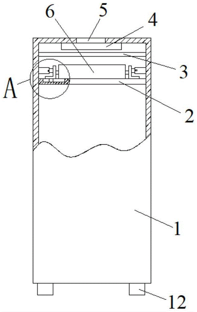
图1是本实用新型计算机光驱固定装置的结构示意图;1 is a schematic structural diagram of a computer optical drive fixing device of the present invention;
图2是图1中A处放大图;Fig. 2 is the enlarged view of A place in Fig. 1;
图3是推力组件的结构示意图;Fig. 3 is the structural representation of thrust assembly;
图中标记为:1、主机箱;2、支撑板;3、防尘网;4、散热风扇;5、通风孔;6、光驱;7、锁止杆;8、固定块;9、推力杆;10、定位杆;11、导向杆;12、垫块;13、滑块;14、滑槽;15、第一弹簧;16、第二弹簧。Marked as: 1. Main box; 2. Supporting plate; 3. Dust filter; 4. Cooling fan; 5. Ventilation hole; 6. Optical drive; 7. Locking lever; 8. Fixing block; ; 10, positioning rod; 11, guide rod; 12, pad; 13, slider; 14, chute; 15, first spring; 16, second spring.
具体实施方式Detailed ways
下面对照附图,通过对实施例的描述,对本实用新型的具体实施方式作进一步详细的说明,目的是帮助本领域的技术人员对本实用新型的构思、技术方案有更完整、准确和深入的理解,并有助于其实施。Below with reference to the accompanying drawings, through the description of the embodiments, the specific implementation of the present utility model will be described in further detail, in order to help those skilled in the art to have a more complete, accurate and in-depth understanding of the concept and technical solutions of the present utility model , and facilitate its implementation.
如图1至图3所示,本实用新型提供了一种计算机光驱固定装置,包括用于放置光驱的支撑板2和用于对光驱施加夹紧力的夹持机构,夹持机构包括可移动的设置于支撑板2上的滑动座、设置于滑动座上的锁止杆7和用于对滑动座施加使其移动的弹性作用力的推力组件,光驱具有让锁止杆7插入的锁止槽,锁止槽设置在光驱的侧面上。As shown in FIG. 1 to FIG. 3 , the present invention provides a computer optical drive fixing device, including a
具体地说,如图1至图3所示,支撑板2设置在计算机主机箱1的内部,支撑板2为水平设置,支撑板2与主机箱1固定连接,光驱放置在支撑板2的顶面上,支撑板2的顶面为水平面,支撑板2对光驱提供支撑作用。滑动座为可移动的设置于支撑板2上且滑动座的移动方向为水平方向,滑动座的移动方向并与主机箱1的宽度方向相平行,支撑板2的顶面设置让滑动座嵌入的滑槽14,该滑槽14对滑动座起导向作用。Specifically, as shown in FIG. 1 to FIG. 3 , the
如图1至图3所示,推力组件包括导向杆11、可移动的设置于导向杆11中且与滑动座连接的推力杆9和设置于导向杆11中且对推力杆9施加弹性作用力的第一弹簧15,导向杆11为内部中空的结构且导向杆11位于支撑板2的上方。导向杆11为水平设置,导向杆11具有一定的长度且导向杆11的长度方向与滑动座的移动方向相平行,滑动座位于导向杆11和光驱之间,导向杆11的一端与主机箱1固定连接,导向杆11的另一端具有让推力杆9通过的开口,导向杆11的内腔体为圆形腔体,且导向杆11的内腔体的轴线与导向杆11的长度方向相平行。推力杆9为圆柱体,推力杆9与导向杆11为同轴设置,第一弹簧15设置在导向杆11的内腔体中,第一弹簧15为圆柱螺旋弹簧且为压缩弹簧,第一弹簧15夹在推力杆9与导向杆11的内壁面之间,第一弹簧15对推力杆9施加的弹性作用力使得推力杆9具有朝向导向杆11的外部伸出的趋势,进而可以推动滑动座朝向靠近光驱的方向进行移动,最终使得锁止杆7能够插入光驱上的锁止槽中,实现光驱的夹紧固定。推力杆9的一端插入导向杆11的内腔体中,推力杆9的另一端与滑动座固定连接,推力杆9和锁止杆7分别位于滑动座的两侧。As shown in FIG. 1 to FIG. 3 , the thrust assembly includes a
如图1至图3所示,推力组件还包括可移动的设置于推力杆9上的定位杆10和设置于推力杆9上且对定位杆10施加弹性作用力的第二弹簧16,导向杆11具有让定位杆10插入的定位孔。推力杆9具有容纳第二弹簧16和定位杆10的容置槽,定位杆10的移动方向与推力杆9的移动方向相垂直,容置槽在推力杆9的外圆面上形成让定位杆10通过的开口。第二弹簧16为圆柱螺旋弹簧且为压缩弹簧,第二弹簧16夹在定位杆10与推力杆9的内壁面之间,第二弹簧16的一端与定位杆10固定连接,第二弹簧16的另一端与推力杆9固定连接,第二弹簧16对定位杆10施加的弹性作用力使得定位杆10具有朝向推力杆9的外部伸出的趋势,进而可以推动定位杆10插入到定位孔中。定位孔为在导向杆11的侧壁上沿壁厚方向贯穿设置的通孔,容置槽设置在推力杆9的位于导向杆11的内腔体中的一端。在第一弹簧15推动推力杆9朝向导向杆11外部移动过程中,当容置槽与导向杆11上的定位孔对齐后,在第二弹簧16的作用下,定位杆10朝向容置槽外部移动,定位杆10能够插入到定位孔中,最终定位杆10的一部分位于定位孔中,另一部分位于容置槽中,从而在推力杆9的轴向上对推力杆9起到限位作用,避免推力杆9、滑动座和锁止杆7出现移动,进而避免光驱出现晃动,提高可靠性。在需要拆卸光驱时,需先使用工具将定位杆10按入容置槽中,解除对推力杆9的限位,然后可以朝向导向杆11推动滑动座进行移动,滑动座带动锁止杆7移动,将锁止杆7从光驱的锁止槽中抽出,进而实现光驱的解锁,光驱可以被从支撑板2上取下。As shown in FIG. 1 to FIG. 3 , the thrust assembly further includes a
如图1至图3所示,滑动座是由相连接的固定块8和滑块13组成,固定块8位于支撑板2的顶面上,滑块13位于固定块8的下方且滑块13与固定块8的底面固定连接,滑块13嵌入滑槽14中,滑块13与滑槽14相配合起导向作用,固定块8位于导向杆11和光驱之间,固定块8与推力杆9和锁止杆7固定连接。As shown in FIGS. 1 to 3 , the sliding seat is composed of a
如图1至图3所示,锁止杆7的长度方向与导向杆11的长度方向相平行,锁止杆7位于支撑板2的上方,锁止杆7的一端与滑动座固定连接,锁止杆7的另一端套设有用于插入锁止槽中的缓冲垫,缓冲垫采用橡胶材质支撑,缓冲垫包裹锁止杆7的远离滑动座的端部且缓冲垫与锁止杆7固定连接,缓冲垫用于插入光驱的锁止槽中且缓冲垫与光驱相接触,避免锁止杆7直接接触光驱,光驱不容易损坏,橡胶垫使光驱更加稳定。As shown in FIGS. 1 to 3 , the length direction of the locking
如图1所示,在本实施例中,夹持机构设置两个,两个夹持机构为相对布置且两个夹持机构处于与主机箱1的宽度方向相平行的同一直线上,光驱位于两个夹持机构之间,光驱由两个夹持机构共同夹紧固定,可靠性更高。As shown in FIG. 1 , in this embodiment, two clamping mechanisms are provided, the two clamping mechanisms are arranged opposite to each other, and the two clamping mechanisms are on the same line parallel to the width direction of the
如图1所示,本实用新型的计算机光驱固定装置还包括用于对光驱进行散热的散热风扇4,散热风扇4设置于主机箱1的内部且散热风扇4位于光驱的正上方,主机箱1的顶面设置有通风孔5,散热风扇4位于该通风孔5的下方,散热风扇4的型号为W2E250-HL06-01。As shown in FIG. 1 , the computer optical drive fixing device of the present invention also includes a cooling
以上结合附图对本实用新型进行了示例性描述。显然,本实用新型具体实现并不受上述方式的限制。只要是采用了本实用新型的方法构思和技术方案进行的各种非实质性的改进;或未经改进,将本实用新型的上述构思和技术方案直接应用于其它场合的,均在本实用新型的保护范围之内。The present invention has been exemplarily described above with reference to the accompanying drawings. Obviously, the specific implementation of the present invention is not limited by the above manner. As long as the method concept and technical solution of the present invention are adopted for various non-substantial improvements; or without improvement, the above-mentioned concept and technical solution of the present invention are directly applied to other occasions, all of which are included in the present invention. within the scope of protection.
Claims (6)
Priority Applications (1)
| Application Number | Priority Date | Filing Date | Title |
|---|---|---|---|
| CN201920338769.2U CN211236775U (en) | 2019-03-18 | 2019-03-18 | computer optical drive mount |
Applications Claiming Priority (1)
| Application Number | Priority Date | Filing Date | Title |
|---|---|---|---|
| CN201920338769.2U CN211236775U (en) | 2019-03-18 | 2019-03-18 | computer optical drive mount |
Publications (1)
| Publication Number | Publication Date |
|---|---|
| CN211236775U true CN211236775U (en) | 2020-08-11 |
Family
ID=71919083
Family Applications (1)
| Application Number | Title | Priority Date | Filing Date |
|---|---|---|---|
| CN201920338769.2U Active CN211236775U (en) | 2019-03-18 | 2019-03-18 | computer optical drive mount |
Country Status (1)
| Country | Link |
|---|---|
| CN (1) | CN211236775U (en) |
-
2019
- 2019-03-18 CN CN201920338769.2U patent/CN211236775U/en active Active
Similar Documents
| Publication | Publication Date | Title |
|---|---|---|
| CN211890625U (en) | Special-shaped parts processing and assembly console | |
| CN208141310U (en) | A kind of easy-to-dismount computer box structure of computer teaching | |
| CN102109893A (en) | Hard disk drive reversible screw-free fixing structure | |
| CN216928039U (en) | Hard disk quick-dismantling bracket and integrated machine back plate | |
| CN209026028U (en) | A kind of precision bearing bearing block | |
| CN210776496U (en) | Hard disk mounting rack in desk computer mainframe box | |
| CN212342281U (en) | Computer hard disk shock protection device | |
| CN212032065U (en) | Computer hard disk protection device | |
| CN219512823U (en) | A data storage device that is easy to disassemble | |
| CN224096186U (en) | Computer hard disk fixing frame convenient to detach | |
| CN219958142U (en) | An industrial computer hard disk installation component | |
| CN208027243U (en) | A kind of picture pooled storage | |
| CN222965629U (en) | Computer hard disk mounting structure | |
| CN220425816U (en) | A dispensing fixture with positioning | |
| CN209265350U (en) | A kind of gauge device for hard disk installation | |
| CN212156360U (en) | Building electromechanical device installs fixing device | |
| CN211828125U (en) | A new type of computer hard disk fixing device | |
| CN216352089U (en) | Hard disk mounting structure for computer | |
| CN221850543U (en) | A cold press for wood board processing | |
| CN219027215U (en) | Clamping structure | |
| CN223217832U (en) | Solid state disk bracket for computer | |
| CN223193318U (en) | Quick-dismantling and exchanging structure for front window of case | |
| CN219269288U (en) | A controller shell that is convenient for positioning and installation | |
| CN222028589U (en) | Quick detach formula heat abstractor and quick-witted case | |
| CN220829714U (en) | Computer hard disk encryption device |
Legal Events
| Date | Code | Title | Description |
|---|---|---|---|
| GR01 | Patent grant | ||
| GR01 | Patent grant |