CN211219719U - A Z-shaped longitudinal beam one-time processing and forming device - Google Patents
A Z-shaped longitudinal beam one-time processing and forming device Download PDFInfo
- Publication number
- CN211219719U CN211219719U CN201922094009.4U CN201922094009U CN211219719U CN 211219719 U CN211219719 U CN 211219719U CN 201922094009 U CN201922094009 U CN 201922094009U CN 211219719 U CN211219719 U CN 211219719U
- Authority
- CN
- China
- Prior art keywords
- pressing device
- longitudinal beam
- shaped longitudinal
- horizontal
- time processing
- Prior art date
- Legal status (The legal status is an assumption and is not a legal conclusion. Google has not performed a legal analysis and makes no representation as to the accuracy of the status listed.)
- Active
Links
Images


Landscapes
- Jigs For Machine Tools (AREA)
Abstract
本实用新型一种Z形纵梁一次加工成型装置,属于机械加工技术领域,解决Z形纵梁加工精度不高,加工难度大的问题;具体是通过在工作平台两侧设置上部、下部以及左右的可调节顶紧装置对Z形纵梁的上下端部和中部上下表面在倾斜和水平两个状态下进行顶紧定位,使Z形纵梁在倾斜和水平两个加工面进行切换,在Z形纵梁不翻货加工的同时实现角度转变过程中快速、精确夹紧定位,从而提高生产效率,降低劳动强度,有效保证位置尺寸精度,提高Z形纵梁的合格率。
The utility model relates to a one-time processing and forming device for a Z-shaped longitudinal beam, which belongs to the technical field of mechanical processing, and solves the problems of low processing precision and high processing difficulty of the Z-shaped longitudinal beam; The adjustable jacking device performs jacking and positioning on the upper and lower ends of the Z-shaped longitudinal beam and the upper and lower surfaces of the middle part in two states: inclined and horizontal, so that the Z-shaped longitudinal beam can be switched between the inclined and horizontal processing surfaces. The longitudinal beam is not turned over and processed, and at the same time, it realizes fast and accurate clamping and positioning during the angle change process, thereby improving production efficiency, reducing labor intensity, effectively ensuring the position and dimensional accuracy, and improving the qualification rate of Z-shaped longitudinal beam.
Description
技术领域technical field
本实用新型属于机械加工技术领域,涉及一种机加定位装置,具体为一种Z形纵梁一次加工成型装置。The utility model belongs to the technical field of mechanical processing, and relates to a machined positioning device, in particular to a one-time processing and forming device for a Z-shaped longitudinal beam.
背景技术Background technique
Z形纵梁的截面呈英文字母Z形,所以称之为Z形纵梁,Z形纵梁在越野车底盘中应用较为广泛,起支撑、连接汽车各个总成,使各总成保持相对正确位置,并承担汽车内外各种载荷的作用。Z形纵梁长越1.9米,由厚10mm、与水平面呈一定夹角的Z型基体和两个L型件焊接而成,对于Z形纵梁需进行Z型基体上下斜面的水平加工、斜端面加工、垂直端面加工、0°平面各槽和220-φ17连接孔加工,其端面加工精度和孔位置精度直接影响着其余零部件能否顺利装配完成。根据现有加工设备,纵梁加工时需进行多次翻货,费时费力且加工难度大、生产效率低、安全隐患大,尤其220-φ17连接孔为倾斜面加工,孔加工位置尺寸无法保证,造成连接孔频繁干涉现象,致使无法实现各零部件与纵梁的正常连接装配,严重影响了加工精度及生产进度,已成为制约生产的技术瓶颈。The cross section of the Z-shaped longitudinal beam is in the shape of the English letter Z, so it is called the Z-shaped longitudinal beam. The Z-shaped longitudinal beam is widely used in the chassis of off-road vehicles, supporting and connecting the various assemblies of the car, so that the assemblies remain relatively correct. position, and bear the role of various loads inside and outside the car. The Z-shaped longitudinal beam is 1.9 meters long and is welded by a Z-shaped base with a thickness of 10 mm and a certain angle with the horizontal plane and two L-shaped parts. , Vertical end face machining, 0° plane slots and 220-φ17 connection hole machining, the end face machining accuracy and hole position accuracy directly affect whether the rest of the components can be assembled smoothly. According to the existing processing equipment, the longitudinal beam needs to be turned over many times during processing, which is time-consuming and labor-intensive, with high processing difficulty, low production efficiency, and great potential safety hazards. In particular, the 220-φ17 connecting hole is processed on an inclined surface, and the size of the hole processing position cannot be guaranteed. The frequent interference of connecting holes makes it impossible to realize the normal connection and assembly of various components and longitudinal beams, which seriously affects the machining accuracy and production progress, and has become a technical bottleneck restricting production.
实用新型内容Utility model content
本实用新型克服了现有技术的不足,提出一种Z形纵梁一次加工成型装置,目的是实现对于Z形不规则零件在机加定位时的快速、精确夹紧。解决Z形纵梁加工精度不高,加工难度大的问题。The utility model overcomes the deficiencies of the prior art, and proposes a Z-shaped longitudinal beam one-time processing and forming device, which aims to realize fast and precise clamping of Z-shaped irregular parts during machining and positioning. Solve the problems of low processing precision and difficult processing of Z-shaped longitudinal beams.
为了达到上述目的,本实用新型是通过如下技术方案实现的。In order to achieve the above purpose, the present invention is achieved through the following technical solutions.
一种Z形纵梁一次加工成型装置,包括水平工作台,所述水平工作台的一侧设置有左上压紧装置、左下支撑装置、第一侧向顶紧装置;所述水平工作台的另一侧设置有右上压紧装置、右下支撑装置、第二侧向顶紧装置;所述第一侧向顶紧装置位于水平工作台的上方,所述第二侧向顶紧装置位于水平工作台的下方;所述左上压紧装置、左下支撑装置、第一侧向顶紧装置以及右上压紧装置、右下支撑装置和第二侧向顶紧装置都包括调节杆和顶紧端部,所述顶紧端部可拆卸连接在调节杆的一端,顶紧端部与Z形纵梁接触的一端为平面或斜面;所述调节杆用于根据Z形纵梁的尺寸调节顶紧端部的伸缩长度使顶紧端部与Z形纵梁的接触面贴合并将Z形纵梁的上下左右各面位置固定。A Z-shaped longitudinal beam one-time processing and forming device includes a horizontal workbench, one side of the horizontal workbench is provided with a left upper pressing device, a left lower support device, and a first side pressing device; the other side of the horizontal workbench is provided with One side is provided with an upper right pressing device, a lower right supporting device, and a second lateral pressing device; the first lateral pressing device is located above the horizontal workbench, and the second lateral pressing device is located on the horizontal working table. below the table; the upper left pressing device, the lower left supporting device, the first lateral pressing device, the upper right pressing device, the lower right supporting device and the second lateral pressing device all include an adjusting rod and a pressing end, The jacking end is detachably connected to one end of the adjusting rod, and the end of the jacking end in contact with the Z-shaped longitudinal beam is a plane or inclined plane; the adjusting rod is used to adjust the jacking end according to the size of the Z-shaped longitudinal beam The telescopic length makes the top end part fit with the contact surface of the Z-shaped longitudinal beam and fix the position of the upper, lower, left, and right surfaces of the Z-shaped longitudinal beam.
进一步的,所述顶紧端部通过螺栓连接在调节杆的一端。Further, the tightening end is connected to one end of the adjusting rod through a bolt.
进一步的,所述的左上压紧装置、左下支撑装置和第一侧向顶紧装置设置在第一支撑架上;所述右上压紧装置、右下支撑装置、第二侧向顶紧装置设置在第二支撑架上。Further, the upper left pressing device, the lower left supporting device and the first lateral pressing device are arranged on the first support frame; the upper right pressing device, the lower right supporting device and the second lateral pressing device are arranged on the second support frame.
更进一步的,还包括底座,所述水平工作台设置在底座上,第一支撑架和第二支撑架与底座相连接并分别设置在底座的左右两端。Further, it also includes a base, the horizontal worktable is arranged on the base, the first support frame and the second support frame are connected to the base and are respectively arranged at the left and right ends of the base.
所述第一支撑架的上端通过第一连接杆与左上压紧装置相连接,下端通过第二连接杆与左下支撑装置相连接,所述左上压紧装置和左下支撑装置的调节杆分别垂直于水平工作面,左上压紧装置和左下支撑装置的顶紧端部分别朝向水平工作面相对设置,所述第一侧向顶紧装置的调节杆连接在第一支撑架的连接孔上,并通过螺栓固定。The upper end of the first support frame is connected with the upper left pressing device through a first connecting rod, and the lower end is connected with the lower left supporting device through a second connecting rod. The adjustment rods of the upper left pressing device and the lower left supporting device are respectively perpendicular to On the horizontal working surface, the pressing ends of the upper left pressing device and the lower left supporting device are respectively arranged opposite to the horizontal working surface, and the adjusting rod of the first lateral pressing device is connected to the connecting hole of the first supporting frame, and passes through the Bolted.
所述第二支撑架的上端通过第三连接杆与右上压紧装置相连接,下端通过第四连接杆与右下支撑装置相连接,所述右上压紧装置和右下支撑装置的调节杆分别垂直于水平工作面,右上压紧装置和右下支撑装置的顶紧端部分别朝向水平工作面相对设置,所述第二侧向顶紧装置的调节杆连接在第二支撑架的连接孔上,并通过螺栓固定。The upper end of the second support frame is connected with the upper right pressing device through the third connecting rod, and the lower end is connected with the lower right supporting device through the fourth connecting rod, and the adjustment rods of the upper right pressing device and the lower right supporting device are respectively Perpendicular to the horizontal working surface, the upper right pressing device and the lower right supporting device are respectively arranged oppositely facing the horizontal working surface, and the adjusting rod of the second lateral pressing device is connected to the connecting hole of the second supporting frame , and fastened with bolts.
进一步的,所述的第一侧向顶紧装置包括第一平面顶紧装置和第一斜面顶紧装置;所述的第二侧向顶紧装置包括第二平面顶紧装置和第二斜面顶紧装置。Further, the first lateral pressing device includes a first flat pressing device and a first inclined pressing device; the second lateral pressing device includes a second flat pressing device and a second inclined pressing device. tighten the device.
进一步的,还包括水平支撑垫块或斜支撑垫块,用于对固定好的Z形纵梁进行支撑定位。Further, it also includes a horizontal support block or an oblique support block, which is used for supporting and positioning the fixed Z-shaped longitudinal beam.
基于所述装置的Z形纵梁一次加工成型的方法,所述Z形纵梁由纵向的斜面基体和连接在基体上下两端的平面基体组成,所述上下两端连接的两个平面基体相平行;具体方法包括以下步骤:Based on the one-time processing and forming method of the Z-shaped longitudinal beam of the device, the Z-shaped longitudinal beam is composed of a longitudinal inclined plane base body and a plane base body connected at the upper and lower ends of the base body, and the two plane base bodies connected at the upper and lower ends are parallel to each other. ; The specific method includes the following steps:
a)Z形纵梁的倾斜角度加工:将Z形纵梁置于水平工作台上,用第一侧向顶紧装置和第二侧向顶紧装置的顶紧端部分别对Z形纵梁上下两端的平面基体进行定位顶紧;之后分别调节左上压紧装置、左下支撑装置、右上压紧装置和右下支撑装置的调节杆使其上的顶紧端部与所述斜面基体的上下表面贴合并顶紧;使斜面基体的上下表面悬空,此时对斜面基体的上下表面进行钻孔或开槽操作;由于此时倾斜角度状态下,斜面基体与水平面形成一定角度,而两端平面基体为垂直与水平面,故将左上压紧装置、左下支撑装置、右上压紧装置和右下支撑装置的顶紧端部与斜面基体接触的一面设置为斜面,以与斜面基体完全贴合;将第一侧向顶紧装置和第二侧向顶紧装置的顶紧端部设置为平面,以与平面基体完全贴合。a) Machining of the inclination angle of the Z-shaped longitudinal beam: place the Z-shaped longitudinal beam on the horizontal workbench, and use the top end of the first lateral clamping device and the second lateral clamping device to respectively align the Z-shaped longitudinal beam The flat bases at the upper and lower ends are positioned and tightened; then the adjustment rods of the upper left pressing device, the lower left supporting device, the upper right pressing device and the lower right supporting device are respectively adjusted so that the upper and lower pressing ends of the upper and lower surfaces of the inclined plane base are in contact with each other. Fit and press tightly; the upper and lower surfaces of the inclined plane base are suspended, and then the upper and lower surfaces of the inclined plane base are drilled or slotted; because the inclined plane base forms a certain angle with the horizontal plane, while the two ends of the flat base Because of the vertical and horizontal planes, the top left pressing device, the lower left supporting device, the upper right pressing device and the lower right supporting device are set as the inclined surface on the side that is in contact with the inclined plane base, so as to fit the inclined plane base completely; The pressing ends of the one side pressing device and the second lateral pressing device are set to be flat, so as to be completely fit with the flat base.
b)Z形纵梁的水平角度加工:将左上压紧装置、左下支撑装置、右上压紧装置、右下支撑装置、第一侧向顶紧装置和第二侧向顶紧装置的调节杆全部旋出,将Z形纵梁的斜面基体贴合在水平工作台上,调节左上压紧装置和右上压紧装置的调节杆,使其顶紧端部贴合斜面基体的上表面并通过螺栓紧固;再将第一侧向顶紧装置和第二侧向顶紧装置的顶紧端部分别对Z形纵梁上下两端的平面基体进行定位顶紧;此状态可实现中间平面各槽以及连接孔的垂直加工;由于此时水平状态下,斜面基体呈水平面状态,而两端平面基体与水平面形成夹角,故将左上压紧装置、右上压紧装置的顶紧端部与斜面基体接触的一面设置为平面,以与斜面基体完全贴合;将第一侧向顶紧装置和第二侧向顶紧装置的顶紧端部设置为斜面,以与平面基体完全贴合。b) Horizontal angle processing of the Z-shaped longitudinal beam: All the adjustment rods of the upper left pressing device, the lower left supporting device, the upper right pressing device, the lower right supporting device, the first lateral pressing device and the second lateral pressing device Unscrew it, fit the inclined surface base of the Z-shaped longitudinal beam on the horizontal workbench, adjust the adjustment rods of the upper left pressing device and the upper right pressing device, so that the top tightening end fits the upper surface of the inclined surface base and is tightened by bolts. Then, the top end of the first side pressing device and the second side pressing device are respectively positioned and pressed to the plane bases at the upper and lower ends of the Z-shaped longitudinal beam; in this state, each slot and connection of the middle plane can be realized. The vertical processing of the hole; since the inclined plane base is in a horizontal state at this time, and the flat base at both ends forms an angle with the horizontal plane, the top left pressing device and the top right pressing device are in contact with the inclined plane base. One side is set as a flat surface to fully fit with the inclined surface base; the top pressing ends of the first lateral pressing device and the second lateral pressing device are set as inclined surfaces to fully fit with the flat base.
优选的,步骤a中,在倾斜角度状态下的斜面基体下部设置具有斜面的垫块进行支撑。Preferably, in step a, the lower part of the inclined plane base body in the inclined angle state is provided with a cushion block with an inclined plane for support.
本实用新型相对于现有技术所产生的有益效果为:The beneficial effect that the present utility model produces with respect to the prior art is:
1、本实用新型对于Z形纵梁实现不翻货便可实现定位机加上下平面、两侧端面;Z形纵梁倾斜角度和水平加工状态自由转变;同时在Z形纵梁角度转变过程中实现快速、精确夹紧定位,从而实现产品加工状态的快速转换、精确夹紧和松货,从而提高生产效率。1. The utility model can realize the positioning machine plus the lower plane and the end faces on both sides for the Z-shaped longitudinal beam without turning over the goods; the Z-shaped longitudinal beam inclination angle and the horizontal processing state can be freely changed; Realize fast and precise clamping and positioning, so as to realize rapid changeover of product processing status, precise clamping and loosening, thereby improving production efficiency.
2、本实用新型减少了大量人工位置对正、角度调节、压紧调整工作,从而大大降低劳动强度。2. The utility model reduces a lot of manual position alignment, angle adjustment, and compression adjustment work, thereby greatly reducing labor intensity.
3、本实用新型采用角度可调型装夹定位装置,实现产品不翻货加工,可从根源上大大减少安全隐患。3. The utility model adopts an angle-adjustable clamping and positioning device to realize the product processing without turning over the goods, which can greatly reduce the potential safety hazards from the root.
4、本实用新型将连接孔由斜面加工转换为平面垂直加工,从而有效保证位置尺寸精度,合格率即可保证。4. The utility model converts the connection hole from the inclined surface processing to the plane vertical processing, thereby effectively ensuring the position and dimensional accuracy, and the qualified rate can be guaranteed.
附图说明Description of drawings
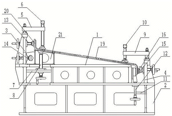
图1为本实用新型所述Z形纵梁一次加工成型装置在斜面基体倾斜状态下的连接示意图。FIG. 1 is a schematic diagram of the connection of the Z-shaped longitudinal beam one-time processing and forming device according to the present invention when the inclined plane base body is inclined.
图2为本实用新型所述Z形纵梁一次加工成型装置在斜面基体水平状态下的连接示意图。FIG. 2 is a schematic diagram of the connection of the Z-shaped longitudinal beam one-time processing and forming device according to the present invention in the horizontal state of the inclined plane base.
其中,1为水平工作台,2为底座,3为第一支撑架,4为第二支撑架,5为第一连接杆,6为左上压紧装置,7为第二连接杆,8为左下支撑装置,9为第三连接杆,10为右上压紧装置,11为第四连接杆,12为右下支撑装置,13为第一平面顶紧装置,14为第一斜面顶紧装置,15为第二平面顶紧装置,16为第二斜面顶紧装置,17为调节杆,18为顶紧端部,19为斜面基体,20为平面基体,21为垫块。Among them, 1 is the horizontal workbench, 2 is the base, 3 is the first support frame, 4 is the second support frame, 5 is the first connecting rod, 6 is the upper left pressing device, 7 is the second connecting rod, and 8 is the lower left Supporting device, 9 is the third connecting rod, 10 is the upper right pressing device, 11 is the fourth connecting rod, 12 is the lower right supporting device, 13 is the first plane pressing device, 14 is the first inclined plane pressing device, 15 16 is the second inclined surface clamping device, 17 is the adjusting rod, 18 is the clamping end, 19 is the inclined plane base, 20 is the plane base, and 21 is the cushion block.
具体实施方式Detailed ways
为了使本实用新型所要解决的技术问题、技术方案及有益效果更加清楚明白,结合实施例和附图,对本实用新型进行进一步详细说明。应当理解,此处所描述的具体实施例仅仅用以解释本实用新型,并不用于限定本实用新型。下面结合实施例及附图详细说明本实用新型的技术方案,但保护范围不被此限制。In order to make the technical problems, technical solutions and beneficial effects to be solved by the present utility model clearer, the present utility model will be further described in detail with reference to the embodiments and the accompanying drawings. It should be understood that the specific embodiments described herein are only used to explain the present invention, and are not intended to limit the present invention. The technical solutions of the present utility model will be described in detail below with reference to the embodiments and the accompanying drawings, but the protection scope is not limited by this.
如图1和2所示,一种99° Z形纵梁一次加工成型装置,用于对99° Z形纵梁在机加定位时的快速、精确夹紧。99°Z形纵梁具体结构为长1.9米,由厚10mm、99°斜面基体19和焊接在斜面基体19两端的两个厚8mm、99°平面基体20组成,两个平面基体20相平行;对其需进行99°上下斜面的水平加工、60°斜端面加工、90°端面加工、0°平面各槽和220-φ17连接孔加工,其端面加工精度和孔位置精度直接影响着其余零部件能否顺利装配完成。As shown in Figures 1 and 2, a 99° Z-shaped longitudinal beam one-time processing and forming device is used for fast and precise clamping of the 99° Z-shaped longitudinal beam during machining and positioning. The specific structure of the 99° Z-shaped longitudinal beam is 1.9 meters long, and consists of a 10mm thick, 99°
装置具体包括水平工作台1和底座2,水平工作台1固定设置在底座2上的中间位置,底座2的左端连接有第一支撑架3,右端连接有第二支撑架4。第一支撑架3上端通过第一连接杆5连接有左上压紧装置6,下端通过第二连接杆7连接有左下支撑装置8,第一支撑架3上通过连接孔和螺栓连接有第一平面顶紧装置13和第一斜面顶紧装置14;第二支撑架4的上端通过第三连接杆9连接有右上压紧装置10,下端通过第四连接杆11连接有右下支撑装置12,第二支撑架4上通过连接孔和螺栓连接有第二平面顶紧装置15和第二斜面顶紧装置16。The device specifically includes a
其中,第一平面顶紧装置13和第一斜面顶紧装置14位于水平工作台1的上方,第二平面顶紧装置15和第二斜面顶紧装置16位于水平工作台1的下方。Wherein, the first flat
左上压紧装置6、左下支撑装置8、第一平面顶紧装置13和第一斜面顶紧装置14以及右上压紧装置10、右下支撑装置12和第二平面顶紧装置15和第二斜面顶紧装置16的结构都包括调节杆17和顶紧端部18,顶紧端部18通过螺栓可拆卸连接在调节杆17的一端,顶紧端部18与Z形纵梁接触的一端为与其贴合设置为平面或斜面两种结构;所述调节杆17用于根据Z形纵梁的尺寸调节顶紧端部18的伸缩长度使顶紧端部18与Z形纵梁的接触面贴合并将Z形纵梁的上下左右各面位置固定。The upper left
所述左上压紧装置6和左下支撑装置8的调节杆17分别垂直于水平工作面1,左上压紧装置6和左下支撑装置8的顶紧端部18分别朝向水平工作面1相对设置;右上压紧装置10和右下支撑装置12的调节杆17分别垂直于水平工作面1,右上压紧装置10和右下支撑装置12的顶紧端部18分别朝向水平工作面1相对设置。The adjusting
该装置通过各部件的顶紧和收缩,可实现99°和0°加工状态的快速切换和夹紧定位。The device can achieve quick switching and clamping positioning of 99° and 0° processing states through the jacking and shrinking of each component.
Z形纵梁一次加工成型的方法,具体为以下步骤:The method for forming a Z-shaped longitudinal beam at one time includes the following steps:
a)Z形纵梁的99°倾斜角度加工:将Z形纵梁置于水平工作台上,用第一平面顶紧装置13和第二平面顶紧装置15的顶紧端部18分别对Z形纵梁上下两端的平面基体20进行定位顶紧;之后分别调节左上压紧装置6、左下支撑装置8、右上压紧装置10和右下支撑装置12的调节杆17使其上的顶紧端部18与所述斜面基体19的上下表面贴合并顶紧;使斜面基体19的上下表面悬空,在斜面基体19下部放置具有斜面的垫块21进行支撑。此时对斜面基体19的上下表面进行钻孔或开槽操作;由于此时倾斜角度状态下,斜面基体19与水平面形成一定角度,而两端平面基体20为垂直于水平面,故将左上压紧装置6、左下支撑装置8、右上压紧装置10和右下支撑装置12的顶紧端部18与斜面基体19接触的一面设置为斜面,以与斜面基体19完全贴合;用第一平面顶紧装置13和第二平面顶紧装置15的顶紧端部18为平面,以与平面基体20完全贴合。a) 99° inclination angle processing of Z-shaped longitudinal beam: place the Z-shaped longitudinal beam on a horizontal worktable, and use the top-up
b)Z形纵梁的水平0°角度加工:将左上压紧装置6、左下支撑装置8、右上压紧装置10、右下支撑装置12、第一平面顶紧装置13和第二平面顶紧装置15的调节杆17通过松开螺栓全部旋出,将Z形纵梁的斜面基体19贴合在水平工作台1上,将左上压紧装置6和右上压紧装置10的顶紧端部18更换为平面结构,调节左上压紧装置6和右上压紧装置10的调节杆17,使其顶紧端部18贴合斜面基体19的上表面并通过螺栓紧固;再将第一斜面顶紧装置14和第二斜面顶紧装置16的顶紧端部18分别对Z形纵梁上下两端的平面基体20进行定位顶紧;此状态可实现中间平面各槽以及连接孔的垂直加工;由于此时水平状态下,斜面基体19呈水平面状态,而两端平面基体20与水平面形成夹角,故第一斜面顶紧装置14和第二斜面顶紧装置16的顶紧端部18为斜面,以与平面基体完全贴合。b) Horizontal 0° angle processing of Z-shaped longitudinal beam: press the upper left
以上内容是结合具体的优选实施方式对本实用新型所做的进一步详细说明,不能认定本实用新型的具体实施方式仅限于此,对于本实用新型所属技术领域的普通技术人员来说,在不脱离本实用新型的前提下,还可以做出若干简单的推演或替换,都应当视为属于本实用新型由所提交的权利要求书确定专利保护范围。The above content is a further detailed description of the present invention in conjunction with the specific preferred embodiments, and it cannot be considered that the specific embodiments of the present invention are limited to this. Under the premise of a utility model, some simple deductions or substitutions can also be made, which should be regarded as belonging to the utility model and the scope of patent protection determined by the submitted claims.
Claims (8)
Priority Applications (1)
| Application Number | Priority Date | Filing Date | Title |
|---|---|---|---|
| CN201922094009.4U CN211219719U (en) | 2019-11-28 | 2019-11-28 | A Z-shaped longitudinal beam one-time processing and forming device |
Applications Claiming Priority (1)
| Application Number | Priority Date | Filing Date | Title |
|---|---|---|---|
| CN201922094009.4U CN211219719U (en) | 2019-11-28 | 2019-11-28 | A Z-shaped longitudinal beam one-time processing and forming device |
Publications (1)
| Publication Number | Publication Date |
|---|---|
| CN211219719U true CN211219719U (en) | 2020-08-11 |
Family
ID=71936907
Family Applications (1)
| Application Number | Title | Priority Date | Filing Date |
|---|---|---|---|
| CN201922094009.4U Active CN211219719U (en) | 2019-11-28 | 2019-11-28 | A Z-shaped longitudinal beam one-time processing and forming device |
Country Status (1)
| Country | Link |
|---|---|
| CN (1) | CN211219719U (en) |
Cited By (1)
| Publication number | Priority date | Publication date | Assignee | Title |
|---|---|---|---|---|
| CN110842601A (en) * | 2019-11-28 | 2020-02-28 | 山西航天清华装备有限责任公司 | A Z-shaped longitudinal beam one-time processing and forming device and method |
-
2019
- 2019-11-28 CN CN201922094009.4U patent/CN211219719U/en active Active
Cited By (2)
| Publication number | Priority date | Publication date | Assignee | Title |
|---|---|---|---|---|
| CN110842601A (en) * | 2019-11-28 | 2020-02-28 | 山西航天清华装备有限责任公司 | A Z-shaped longitudinal beam one-time processing and forming device and method |
| CN110842601B (en) * | 2019-11-28 | 2024-07-09 | 山西航天清华装备有限责任公司 | One-step forming device and method for Z-shaped longitudinal beam |
Similar Documents
| Publication | Publication Date | Title |
|---|---|---|
| CN201446412U (en) | A new type of jig for drilling holes on arc surface | |
| CN104128733B (en) | Adjustable welding set | |
| CN203679592U (en) | Adjustable welding tool | |
| CN105436959A (en) | Vehicle lathe rough machining tool for upper rocker arm of vertical milled large-scale key part | |
| CN205074806U (en) | A appurtenance for processing wide diesel engine connecting rod of wedge side wheel has | |
| CN203804585U (en) | Boring fixture for support of large mechanical travelling mechanism | |
| CN219053373U (en) | Lead glass frame splice welding tool | |
| CN110842601A (en) | A Z-shaped longitudinal beam one-time processing and forming device and method | |
| CN205673878U (en) | Pressure plate drilling tooling | |
| CN205096783U (en) | H -beam location frock | |
| CN210997610U (en) | Grip-pad boring grab | |
| CN213615318U (en) | Inclined plane jig for machining inclined plane of special-shaped die part | |
| CN209578902U (en) | Vertical machining center workstation | |
| CN210451909U (en) | Whole car pipe connection frock | |
| CN218836844U (en) | A simple centralized fixed tooling | |
| CN204657803U (en) | A kind of bus body skeleton fixture | |
| CN222327348U (en) | A pressure strip chamfering tool | |
| CN208528612U (en) | Mechanical gripping means is used in a kind of processing | |
| CN224209355U (en) | Special frock of lifting support welding | |
| CN107234468A (en) | A kind of front axle two ends clamp for machining and processing method | |
| CN215546920U (en) | Z-shaped rocker arm clamp | |
| CN205733902U (en) | A Fixture Facilitating Groove Processing of Plate Samples | |
| CN214559208U (en) | A combined fixture for one-time processing of super-long parts | |
| CN212095389U (en) | A drill fixture for drilling uneven workpiece edges | |
| CN214643418U (en) | Adjustable large workpiece load support |
Legal Events
| Date | Code | Title | Description |
|---|---|---|---|
| GR01 | Patent grant | ||
| GR01 | Patent grant |