CN211213618U - Denture belt cleaning device convenient to use - Google Patents
Denture belt cleaning device convenient to use Download PDFInfo
- Publication number
- CN211213618U CN211213618U CN201921784017.5U CN201921784017U CN211213618U CN 211213618 U CN211213618 U CN 211213618U CN 201921784017 U CN201921784017 U CN 201921784017U CN 211213618 U CN211213618 U CN 211213618U
- Authority
- CN
- China
- Prior art keywords
- box body
- fixedly connected
- plate
- movable plate
- bolt
- Prior art date
- Legal status (The legal status is an assumption and is not a legal conclusion. Google has not performed a legal analysis and makes no representation as to the accuracy of the status listed.)
- Expired - Fee Related
Links
- 238000004140 cleaning Methods 0.000 title claims abstract description 25
- 238000007789 sealing Methods 0.000 claims description 10
- 238000003466 welding Methods 0.000 claims 2
- XLYOFNOQVPJJNP-UHFFFAOYSA-N water Substances O XLYOFNOQVPJJNP-UHFFFAOYSA-N 0.000 abstract description 7
- 238000005406 washing Methods 0.000 abstract description 6
- 230000002349 favourable effect Effects 0.000 abstract description 4
- 238000011012 sanitization Methods 0.000 abstract description 2
- 238000000034 method Methods 0.000 description 4
- 230000009471 action Effects 0.000 description 3
- 239000012459 cleaning agent Substances 0.000 description 3
- 230000009286 beneficial effect Effects 0.000 description 2
- 230000006378 damage Effects 0.000 description 2
- 238000007599 discharging Methods 0.000 description 2
- 230000036541 health Effects 0.000 description 2
- 208000014674 injury Diseases 0.000 description 2
- 230000008569 process Effects 0.000 description 2
- 241000894006 Bacteria Species 0.000 description 1
- 208000008312 Tooth Loss Diseases 0.000 description 1
- 208000027418 Wounds and injury Diseases 0.000 description 1
- 238000004026 adhesive bonding Methods 0.000 description 1
- 230000004075 alteration Effects 0.000 description 1
- 230000001680 brushing effect Effects 0.000 description 1
- 230000001055 chewing effect Effects 0.000 description 1
- 230000007812 deficiency Effects 0.000 description 1
- 210000004513 dentition Anatomy 0.000 description 1
- 230000018109 developmental process Effects 0.000 description 1
- 238000006073 displacement reaction Methods 0.000 description 1
- 238000005516 engineering process Methods 0.000 description 1
- 230000001815 facial effect Effects 0.000 description 1
- 230000002496 gastric effect Effects 0.000 description 1
- 230000006872 improvement Effects 0.000 description 1
- 230000003993 interaction Effects 0.000 description 1
- 230000004048 modification Effects 0.000 description 1
- 238000012986 modification Methods 0.000 description 1
- 208000028169 periodontal disease Diseases 0.000 description 1
- 238000005498 polishing Methods 0.000 description 1
- 238000004321 preservation Methods 0.000 description 1
- 238000006467 substitution reaction Methods 0.000 description 1
- 230000036346 tooth eruption Effects 0.000 description 1
- 230000008733 trauma Effects 0.000 description 1
Images



Landscapes
- Brushes (AREA)
Abstract
The utility model discloses a denture cleaning device convenient to use, which comprises a box body, a first movable plate and a second movable plate, wherein one end of the middle part of the upper surface of the box body is provided with an opening, one side of the opening is hinged with a cover, and the cover opening side is fixedly connected with the box body through a buckle; the utility model discloses a be equipped with the motor, cam and first movable plate, and drive the cam through the motor and rotate, cooperation through pivot and connecting plate, and then can make first movable plate and second movable plate do the motion of separating from each other, rub each other through the two, can make the brush hair rub the washing to the denture, can thoroughly clean up the stubborn spot on the denture, and discharge through following the outlet pipe with water, can rub the washing many times to the denture, and then can will remain the sanitizer sanitization on the denture as far as, both be favorable to the saving of denture, be favorable to people's healthy again.
Description
Technical Field
The utility model relates to a denture belt cleaning device technical field specifically is a denture belt cleaning device convenient to use.
Background
The false tooth is an artificial tooth for replacing a lost natural tooth, also called false tooth, and is also called as a cause of severe periodontal disease, decayed tooth, trauma and the like, can cause partial or even complete loss of dentition, can affect the facial appearance, pronunciation and chewing functions after the loss of teeth, increases the gastrointestinal burden, can cause inclined displacement of adjacent teeth if the teeth are not repaired in time, the dentures can be repaired by fixed dentures or removable dentures when the dentures are not provided, and the dentures are gradually accepted by people and enter the daily life of people along with the development of science and technology and the improvement of the living standard, the close related denture cleaning problem is also more and more taken attention by people, and traditional manual brushing mode is neither sanitary nor convenient, generally adopts denture cleaning equipment to wash at present, but present denture cleaning device has some deficiencies, such as:
the belt cleaning device of denture generally adopts sanitizer and clear water among the prior art, forms the impact between vibrations through clear water and the denture, washs the denture, but to gluing stubborn spot on the denture, hardly washs with this kind of mode, clearly surely remains the cleaner on the denture after wasing very easily, not only has the injury to the denture, also can have certain harm to the human body.
SUMMERY OF THE UTILITY MODEL
An object of the utility model is to provide a denture belt cleaning device convenient to use to solve the problem of proposing among the above-mentioned background art.
In order to achieve the above object, the utility model provides a following technical scheme: a denture cleaning device convenient to use comprises a box body, a first moving plate and a second moving plate, wherein one end of the middle part of the upper surface of the box body is provided with an opening, one side of the opening is hinged with a cover, one side of the cover is fixedly connected with the box body through a buckle, a supporting plate is fixedly connected with the middle part of one side of the inner wall of the box body close to the bottom end through a bolt, the upper surface of the supporting plate is fixedly connected with a motor through a bolt, the power output end of the motor is fixedly connected with a rotating rod through a coupler, one end of the rotating rod is fixedly connected with a cam through a bolt, a second spring is welded at the middle part of one side of the inner wall of the box body close to the bottom end, one end of the second spring is welded with a second moving plate, one end of the, one end of the cross rod is fixedly connected with a baffle through a bolt, the baffle is connected with the cam in a sliding manner, a second limiting plate is sleeved at the position, close to one end, of the periphery of the second moving plate, a rotating shaft is inserted in the middle of one side of the connecting plate, the rotating shaft is rotatably connected with the connecting plate through a bearing, the two ends of the rotating shaft are fixedly connected with the box body through bolts, the other end of the cross rod is fixedly connected with a first moving plate through a bolt, a first spring is welded at one end of the first moving plate, the other end of the first spring is welded with the box body, a first limiting plate is sleeved at the position, close to one end, of the periphery of the first moving plate, the first limiting plate is connected with the first moving plate in a sliding manner, and the other end of the first limiting plate is fixedly connected with the box body through a bolt, the adjacent sides of the first movable plate and the second movable plate are provided with grooves, and bristles are adhered to the inner walls of the grooves.
Preferably, an outlet pipe is fixedly connected to one side of the box body close to the bottom end through a bolt, the outlet pipe is communicated with the box body, a sealing cover is in threaded connection with one end of the outlet pipe, and a sealing ring is adhered to the inner wall of the sealing cover close to one end of the sealing cover.
Preferably, a supporting block is fixedly connected to one side of the box body close to the top end of the box body through a bolt, a fan is fixedly connected to the upper surface of the supporting block through a bolt, and the output end of the fan is communicated with the box body.
Preferably, the middle parts of two sides of the inner wall of the box body are fixedly connected with four ultraviolet lamps through bolts.
Preferably, the cam, the baffle and the central line of the first moving plate are on the same straight line, and the first moving plate and the second moving plate are both in cuboid structures.
Preferably, the inner walls of the first limiting plate and the second limiting plate are polished, and the side length of the first moving plate is equal to that of the second moving plate.
Compared with the prior art, the beneficial effects of the utility model are that:
the utility model discloses a be equipped with the motor, cam and first movable plate, and drive the cam through the motor and rotate, cooperation through pivot and connecting plate, and then can make first movable plate and second movable plate do the motion of separating from each other, rub each other through the two, can make the brush hair rub the washing to the denture, can thoroughly clean up the stubborn spot on the denture, and through discharging water from the outlet pipe, can rub the washing many times to the denture, and then can will remain the sanitizer sanitization on the denture as far as, existing saving that is favorable to the denture, be favorable to people's healthy again, and through being equipped with fan and ultraviolet lamp, can air-dry and disinfect denture and belt cleaning device, ensure the clean health of denture and belt cleaning device.
Drawings
FIG. 1 is a schematic sectional view of the present invention;
FIG. 2 is a schematic side view of the cross-sectional structure of the present invention;
FIG. 3 is an enlarged view of the structure at A in FIG. 1;
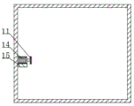
fig. 4 is an enlarged schematic view of a portion B in fig. 1.
In the figure: 1-a box body; 2-opening the cover; 3-a first moving plate; 4-a first spring; 5-a first limiting plate; 6-connecting rod; 7-a second limiting plate; 8-a second moving plate; 9-a second spring; 10-rotating rod; 11-a cam; 12-a baffle plate; 13-a cross-bar; 14-a motor; 15-a support plate; 16-a connecting plate; 17-a rotating shaft; 18-an outlet pipe; 19-a fan; 20-supporting block.
Detailed Description
The technical solutions in the embodiments of the present invention will be described clearly and completely with reference to the accompanying drawings in the embodiments of the present invention, and it is obvious that the described embodiments are only some embodiments of the present invention, not all embodiments. Based on the embodiments in the present invention, all other embodiments obtained by a person skilled in the art without creative work belong to the protection scope of the present invention.
Referring to fig. 1-4, the present invention provides a technical solution: a denture cleaning device convenient to use comprises a box body 1, a first moving plate 3 and a second moving plate 8, wherein an opening is formed in the middle of the upper surface of the box body 1, a cover 2 is hinged to one side of the opening, one side of the cover 2 is fixedly connected with the box body 1 through a buckle, a supporting plate 15 is fixedly connected with a bottom end in the middle of one side of the inner wall of the box body 1 through a bolt, a motor 14 is fixedly connected with the upper surface of the supporting plate 15 through a bolt, the motor 14 is a DRF-W300CA motor, the power output end of the motor 14 is fixedly connected with a rotating rod 10 through a coupler, one end of the rotating rod 10 is fixedly connected with a cam 11 through a bolt, the cam 11, a baffle 12 and the center line of the first moving plate 3 are on the same straight line, the first moving plate 3 and the second moving plate 8 are both in a cuboid structure, and a second spring 9 is welded in, a second movable plate 8 is welded at one end of the second spring 9, a connecting rod 6 is fixedly connected at one end of the second movable plate 8 through bolts, a connecting plate 16 is rotatably connected at one side of the connecting rod 6 through an adapter, a cross rod 13 is rotatably connected at one end of the connecting plate 16 through the adapter, a baffle 12 is fixedly connected at one end of the cross rod 13 through bolts, the baffle 12 is slidably connected with the cam 11, a second limiting plate 7 is sleeved at the position, close to one end, of the periphery of the second movable plate 8, a polishing treatment is adopted for the inner walls of the first limiting plate 5 and the second limiting plate 7, friction between the limiting plates and the movable plates is reduced, the side length of the first movable plate 3 is equal to that of the second movable plate 8, the second limiting plate 7 is slidably connected with the second movable plate 8, and one end of the second limiting plate 7 is fixedly connected with the box, a rotating shaft 17 is inserted in the middle of one side of the connecting plate 16, the rotating shaft 17 is rotatably connected with the connecting plate 16 through a bearing, two ends of the rotating shaft 17 are fixedly connected with the box body 1 through bolts, the other end of the cross rod 13 is fixedly connected with a first movable plate 3 through bolts, one end of the first movable plate 3 is welded with a first spring 4, the other end of the first spring 4 is welded with the box body 1, a first limiting plate 5 is sleeved at the periphery of the first movable plate 3 close to one end, the first limiting plate 5 is slidably connected with the first movable plate 3, the other end of the first limiting plate 5 is fixedly connected with the box body 1 through bolts, grooves are formed in the adjacent sides of the first movable plate 3 and the second movable plate 8, bristles are adhered to the inner walls of the grooves, and an outlet pipe 18 is fixedly connected with one side of the box body 1 close to the, and the outlet pipe 18 is communicated with the box body 1, one end of the outlet pipe 18 is connected with a sealing cover in a threaded manner, and the inner wall of the sealing cover close to one end is stuck with a sealing ring, which can discharge the washing water through an outlet pipe 18 for washing for a plurality of times, thereby reducing the residual cleaning agent on the false teeth as much as possible, one side of the box body 1 close to the top end is fixedly connected with a supporting block 20 through a bolt, the upper surface of the supporting block 20 is fixedly connected with a fan 19 through bolts, the output end of the fan 19 is communicated with the box body 1, the false teeth and the brush hair are air-dried by the fan 19, the false teeth and the brush hair are prevented from being in a humid environment, bacteria are bred to ensure that the false teeth and the false tooth cleaning device are clean and sanitary, ultraviolet lamps are fixedly connected with the middle parts of the two sides of the inner wall of the box body 1 through bolts, and the number of the ultraviolet lamps is four, and the ultraviolet lamps can sterilize the dried false teeth and the bristles.
The working principle is as follows: when the artificial tooth cleaning machine is used, artificial teeth are placed on grooves in the upper surface of the second moving plate 8, a proper amount of water and cleaning agent are added, the motor 14 is electrically connected with an external power supply, the motor 14 is turned on, the rotating rod 10 and the cam 11 can be driven to rotate together, the first moving plate 3 can be pushed to reciprocate left and right through the interaction force between the cam 11 and the first spring 4, when the first moving plate 3 moves to the right side, the first moving plate 3 drives the connecting plate 16 to rotate to the right side, the other end of the connecting plate 16 pulls the second moving plate 8 to move to the left side, so that the first moving plate 3 and the second moving plate 8 rub each other, the artificial teeth are rubbed and cleaned by using bristles, stubborn stains on the artificial teeth can be thoroughly cleaned, and the artificial teeth can be rubbed and cleaned for multiple times by discharging water from the outlet pipe 18, and the cleaning agent remained on the artificial teeth can be cleaned as much as possible, the artificial tooth cleaning machine is beneficial to preservation of artificial teeth and health of people, and can air-dry and disinfect the artificial teeth and the cleaning device by being provided with the fan 19 and the ultraviolet lamp, so that the artificial teeth and the cleaning device are ensured to be clean and sanitary.
It is noted that, herein, relational terms such as first and second, and the like may be used solely to distinguish one entity or action from another entity or action without necessarily requiring or implying any actual such relationship or order between such entities or actions. Also, the terms "comprises," "comprising," or any other variation thereof, are intended to cover a non-exclusive inclusion, such that a process, method, article, or apparatus that comprises a list of elements does not include only those elements but may include other elements not expressly listed or inherent to such process, method, article, or apparatus.
Although embodiments of the present invention have been shown and described, it will be appreciated by those skilled in the art that changes, modifications, substitutions and alterations can be made in these embodiments without departing from the principles and spirit of the invention, the scope of which is defined in the appended claims and their equivalents.
Claims (6)
1. The utility model provides a denture belt cleaning device convenient to use, includes box (1), first movable plate (3) and second movable plate (8), its characterized in that: an opening is formed in one end of the middle of the upper surface of the box body (1), a cover (2) is hinged to one side of the opening, one side of the cover (2) is fixedly connected with the box body (1) through a buckle, a supporting plate (15) is fixedly connected to the middle of one side of the inner wall of the box body (1) close to the bottom end through a bolt, a motor (14) is fixedly connected to the upper surface of the supporting plate (15) through a bolt, a rotating rod (10) is fixedly connected to the power output end of the motor (14) through a coupler, a cam (11) is fixedly connected to one end of the rotating rod (10) through a bolt, a second spring (9) is welded to the middle of one side of the inner wall of the box body (1) close to the bottom end, a second moving plate (8) is welded to one end of the second spring (9), a connecting rod (6), one end of the connecting plate (16) is rotatably connected with a cross rod (13) through an adapter, one end of the cross rod (13) is fixedly connected with a baffle (12) through a bolt, the baffle (12) is slidably connected with the cam (11), a second limiting plate (7) is sleeved at the periphery of the second moving plate (8) close to one end, the second limiting plate (7) is slidably connected with the second moving plate (8), one end of the second limiting plate (7) is fixedly connected with the box body (1) through a bolt, a rotating shaft (17) is inserted in the middle of one side of the connecting plate (16), the rotating shaft (17) is rotatably connected with the connecting plate (16) through a bearing, both ends of the rotating shaft (17) are fixedly connected with the box body (1) through bolts, and the other end of the cross rod (13) is fixedly connected with the first moving plate (3) through a bolt, first movable plate (3) one end welding has first spring (4), first spring (4) other end with box (1) welding, first movable plate (3) periphery is close to one end department and has cup jointed first limiting plate (5), just first limiting plate (5) with first movable plate (3) sliding connection, just first limiting plate (5) other end with box (1) is through bolt fixed connection, all set up flutedly on one side that first movable plate (3) and second movable plate (8) are adjacent, and the recess inner wall has pasted the brush hair.
2. The denture cleaning device for use as claimed in claim 1, wherein: the box body (1) is provided with an outlet pipe (18) close to the bottom end through a bolt in a fixedly connected mode, the outlet pipe (18) is communicated with the box body (1), one end of the outlet pipe (18) is connected with a sealing cover in a threaded mode, and a sealing ring is pasted on the position, close to one end, of the inner wall of the sealing cover.
3. The denture cleaning device for use as claimed in claim 1, wherein: the box body (1) is characterized in that a supporting block (20) is fixedly connected to one side of the box body (1) close to the top end through a bolt, a fan (19) is fixedly connected to the upper surface of the supporting block (20) through a bolt, and the output end of the fan (19) is communicated with the box body (1).
4. The denture cleaning device for use as claimed in claim 1, wherein: the middle parts of two sides of the inner wall of the box body (1) are fixedly connected with four ultraviolet lamps through bolts.
5. The denture cleaning device for use as claimed in claim 1, wherein: cam (11), baffle (12) and first movable plate (3) central line are on same straight line, first movable plate (3) and second movable plate (8) all are the cuboid structure.
6. The denture cleaning device for use as claimed in claim 1, wherein: the inner walls of the first limiting plate (5) and the second limiting plate (7) are polished, and the side length of the first movable plate (3) is equal to that of the second movable plate (8).
Priority Applications (1)
| Application Number | Priority Date | Filing Date | Title |
|---|---|---|---|
| CN201921784017.5U CN211213618U (en) | 2019-10-23 | 2019-10-23 | Denture belt cleaning device convenient to use |
Applications Claiming Priority (1)
| Application Number | Priority Date | Filing Date | Title |
|---|---|---|---|
| CN201921784017.5U CN211213618U (en) | 2019-10-23 | 2019-10-23 | Denture belt cleaning device convenient to use |
Publications (1)
| Publication Number | Publication Date |
|---|---|
| CN211213618U true CN211213618U (en) | 2020-08-11 |
Family
ID=71920636
Family Applications (1)
| Application Number | Title | Priority Date | Filing Date |
|---|---|---|---|
| CN201921784017.5U Expired - Fee Related CN211213618U (en) | 2019-10-23 | 2019-10-23 | Denture belt cleaning device convenient to use |
Country Status (1)
| Country | Link |
|---|---|
| CN (1) | CN211213618U (en) |
-
2019
- 2019-10-23 CN CN201921784017.5U patent/CN211213618U/en not_active Expired - Fee Related
Similar Documents
| Publication | Publication Date | Title |
|---|---|---|
| CN110063808B (en) | Oral care device for removing dental tartar | |
| TWI583361B (en) | Brush head device for multifunctional dental care tool | |
| CN107981529A (en) | All-round full-automatic formula of sucking brush protects integrative intelligent toothbrush head | |
| AU2017100552B4 (en) | Jet Brush | |
| CN204766005U (en) | Towards tooth ware | |
| CN110710949A (en) | Cleaning device for cosmetic tool brush | |
| CN202386816U (en) | Toothbrush with functions of rotating and spraying mouth wash | |
| CN209935344U (en) | A disinfection cleaning device for artificial tooth maintenance | |
| CN206473006U (en) | A kind of facing brush and the oral care box set including the facing brush | |
| CN218528951U (en) | Portable residue processing apparatus | |
| CN201171725Y (en) | Oscillatory type teeth cleaner | |
| CN115553962A (en) | Case is washd with operation instrument to dentist | |
| CN213248761U (en) | A combination device of a rinsing toothbrush and a toothbrush case | |
| CN213156665U (en) | A denture care device | |
| KR20140010321A (en) | Portable automatic teeth brushing set with multi-function | |
| CN221534159U (en) | A portable cleaning instrument for fixed oral orthodontics | |
| CN214678018U (en) | A cleaning device for oral care | |
| CN201491936U (en) | Toothbrush capable of being used transversely and vertically | |
| CN208926671U (en) | Electric toothbrush and electric toothbrush component | |
| CN2198806Y (en) | Health apparatus for cleaning teeth | |
| CN108186146B (en) | Dental tooth washing device | |
| CN208926665U (en) | Tooth brush | |
| CN219594862U (en) | Old patient oral care belt cleaning device | |
| CN215533895U (en) | A toothbrush sterilizing cup that prevents the growth of bacteria | |
| CN216723401U (en) | Automatic shoe washing machine used in shoe machining process |
Legal Events
| Date | Code | Title | Description |
|---|---|---|---|
| GR01 | Patent grant | ||
| GR01 | Patent grant | ||
| CF01 | Termination of patent right due to non-payment of annual fee | ||
| CF01 | Termination of patent right due to non-payment of annual fee |
Granted publication date: 20200811 |