CN211203726U - A high-efficiency landscape light that is easy to install - Google Patents
A high-efficiency landscape light that is easy to install Download PDFInfo
- Publication number
- CN211203726U CN211203726U CN201920963431.6U CN201920963431U CN211203726U CN 211203726 U CN211203726 U CN 211203726U CN 201920963431 U CN201920963431 U CN 201920963431U CN 211203726 U CN211203726 U CN 211203726U
- Authority
- CN
- China
- Prior art keywords
- fixedly connected
- wall
- sliding rod
- block
- threaded cap
- Prior art date
- Legal status (The legal status is an assumption and is not a legal conclusion. Google has not performed a legal analysis and makes no representation as to the accuracy of the status listed.)
- Expired - Fee Related
Links
Images


Landscapes
- Non-Portable Lighting Devices Or Systems Thereof (AREA)
Abstract
本实用新型公开了一种便于安装的高效景观灯,包括灯座,所述灯座的上表面开设有放置槽,放置槽内壁的左侧面开设有安插槽;所述灯座内壁的表面和安插槽内壁的表面均与连接座的表面搭接,连接座的上表面固定连接有高效景观灯本体,高效景观灯本体内壁的右侧面开设有第一通孔。本实用新型通过第一固定板、第二弹性橡胶、第二固定板、得如弹性橡胶、第一螺纹帽、第二螺纹帽、第一螺纹柱、第二螺纹帽、第三螺纹帽、转轴、第一安装架、第二安装架、第一销轴、第二轴承和连接杆之间的相互配合,安装高效景观灯本体时,就不需要在配备灯杆,降低了成本,方便了工作人员对高效景观灯本体进行安装。
The utility model discloses a high-efficiency landscape lamp that is easy to install, comprising a lamp holder, an upper surface of the lamp holder is provided with a placement slot, and the left side of the inner wall of the placement slot is provided with an installation slot; the surface of the inner wall of the lamp holder is provided with a slot; The surface of the inner wall of the He'an socket is overlapped with the surface of the connecting seat, the upper surface of the connecting seat is fixedly connected with the high-efficiency landscape lamp body, and the right side of the inner wall of the high-efficiency landscape lamp body is provided with a first through hole. The utility model adopts the first fixing plate, the second elastic rubber, the second fixing plate, the elastic rubber, the first threaded cap, the second threaded cap, the first threaded column, the second threaded cap, the third threaded cap, and the rotating shaft. , The mutual cooperation between the first mounting frame, the second mounting frame, the first pin shaft, the second bearing and the connecting rod, when installing the high-efficiency landscape lamp body, there is no need to equip the lamp pole, which reduces the cost and facilitates the work. The personnel installed the high-efficiency landscape lamp body.
Description
技术领域technical field
本实用新型涉及便于安装高效景观灯技术领域,具体是一种便于安装的高效景观灯。The utility model relates to the technical field of easy-to-install high-efficiency landscape lamps, in particular to an easy-to-install high-efficiency landscape lamp.
背景技术Background technique
高效景观灯是现代景观中不可缺少的部分,它不仅自身具有较高的观赏性,还强调艺术灯的景观与景区历史文化、周围环境的协调统一。景观灯利用不同的造型、相异的光色与亮度来造景。现在的高效景观灯一般都安装在景区或公园内,但是安装景观灯时,还需要安装灯杆,还需要将灯杆安装在水泥上,但是灯杆只是作为高效景观灯的支撑作用,成本太高,安装过于麻烦,从而急需一种便于安装的高效景观灯。High-efficiency landscape lights are an indispensable part of modern landscapes. They not only have high ornamental properties themselves, but also emphasize the coordination and unity of the landscape of artistic lights with the history and culture of the scenic spot and the surrounding environment. Landscape lights use different shapes, different light colors and brightness to create landscaping. Today's high-efficiency landscape lights are generally installed in scenic spots or parks, but when installing landscape lights, light poles need to be installed, and the light poles need to be installed on cement, but the light poles are only used as a support for high-efficiency landscape lights, and the cost is too high. High, installation is too troublesome, so there is an urgent need for a high-efficiency landscape light that is easy to install.
实用新型内容Utility model content
本实用新型的目的在于提供一种便于安装的高效景观灯,以解决上述背景技术中提出的问题。The purpose of the present invention is to provide a high-efficiency landscape light that is easy to install, so as to solve the problems raised in the above background technology.
为实现上述目的,本实用新型提供如下技术方案:To achieve the above object, the utility model provides the following technical solutions:
一种便于安装的高效景观灯,包括灯座,所述灯座的上表面开设有放置槽,放置槽内壁的左侧面开设有安插槽;所述灯座内壁的表面和安插槽内壁的表面均与连接座的表面搭接,连接座的上表面固定连接有高效景观灯本体,高效景观灯本体内壁的右侧面开设有第一通孔,第一通孔的内壁与第一滑套的表面固定连接,第一滑套的内表面套接有第一滑杆,第一滑杆的右端与第一拉块的左侧面固定连接,第一滑杆的表面与第一卡槽的内壁搭接,第一卡槽开设在连接座的右侧面,第一滑杆的表面套接有第一弹簧,第一弹簧的两端分别与第一拉块的左侧面和第一滑套的右侧面固定连接,安插槽内壁的上表面开设有第二通孔,第二通孔的内壁设置有第二滑套,第二滑套的内表面套接有第二滑杆,第二滑杆的顶端与第二拉块的下表面固定连接,第二滑杆的表面套接有第二弹簧,第二弹簧的两端分别与第二拉块的下表面和第二滑套的上表面固定连接,第二滑杆的表面与第二卡槽的内壁搭接,第二卡槽开设在连接座的上表面。A high-efficiency landscape light that is easy to install, comprising a lamp holder, an upper surface of the lamp holder is provided with a placement slot, and an installation slot is opened on the left side of the inner wall of the placement slot; the surface of the inner wall of the lamp holder and the inner wall of the installation slot are provided. The upper surface of the connecting seat is fixedly connected with the high-efficiency landscape lamp body, and the right side of the inner wall of the high-efficiency landscape lamp body is provided with a first through hole, and the inner wall of the first through hole is connected with the first slide. The surface of the sleeve is fixedly connected, the inner surface of the first sliding sleeve is sleeved with a first sliding rod, the right end of the first sliding rod is fixedly connected with the left side of the first pull block, and the surface of the first sliding rod is connected with the first slot. The inner wall is overlapped, the first slot is opened on the right side of the connecting seat, the surface of the first sliding rod is sleeved with a first spring, and the two ends of the first spring are respectively connected with the left side of the first pull block and the first spring. The right side of the sliding sleeve is fixedly connected, the upper surface of the inner wall of the socket is provided with a second through hole, the inner wall of the second through hole is provided with a second sliding sleeve, and the inner surface of the second sliding sleeve is sleeved with a second sliding rod , the top end of the second sliding rod is fixedly connected with the lower surface of the second sliding block, the surface of the second sliding rod is sleeved with a second spring, and the two ends of the second spring are respectively connected with the lower surface of the second sliding block and the second sliding block. The upper surface of the sleeve is fixedly connected, the surface of the second sliding rod is overlapped with the inner wall of the second clamping groove, and the second clamping groove is opened on the upper surface of the connecting seat.
作为本实用新型的进一步方案:所述灯座的左侧面与第一安装架的右侧面固定连接,第一安装架的上表面设置有第一销轴,第一销轴通过连接杆与第二销轴活动连接,第二销轴设置在第二安装架的上表面,第一安装架和第二安装架的左侧面分别设置有第一固定块和第二固定块,第一固定块的正面和第二固定块的正面分别设置有第一螺纹帽和第二螺纹帽。As a further solution of the present invention: the left side of the lamp holder is fixedly connected with the right side of the first mounting frame, the upper surface of the first mounting frame is provided with a first pin, and the first pin is connected to the first pin through the connecting rod. The second pin is movably connected, the second pin is arranged on the upper surface of the second mounting frame, the left side of the first mounting frame and the second mounting frame are respectively provided with a first fixing block and a second fixing block. The front face of the block and the front face of the second fixing block are respectively provided with a first threaded cap and a second threaded cap.
作为本实用新型的进一步方案:所述第一螺纹帽和第二螺纹帽的内表面均与第一螺纹柱的表面螺纹连接,第一螺纹柱的前端与第一拧块的背面固定连接;所述第一安装架的背面与第二安装架的正面搭接;所述第一安装架内壁的正面通过四个支撑杆与第一固定板的正面固定连接,第一固定板的背面设置有第一弹性橡胶。As a further scheme of the present invention: the inner surfaces of the first threaded cap and the second threaded cap are both threadedly connected to the surface of the first threaded column, and the front end of the first threaded column is fixedly connected to the back of the first screw block; The back of the first installation frame is overlapped with the front of the second installation frame; the front of the inner wall of the first installation frame is fixedly connected to the front of the first fixing plate through four support rods, and the back of the first fixing plate is provided with a An elastic rubber.
作为本实用新型的进一步方案:所述第二安装架的背面设置有两个第三滑套,两个第三滑套的内表面均套接有第三滑杆,第三滑杆的两端分别与限位块的正面和第二固定板的背面固定连接,第二固定板的正面设置有第二弹性橡胶。As a further solution of the present invention: the back of the second mounting frame is provided with two third sliding sleeves, the inner surfaces of the two third sliding sleeves are sleeved with a third sliding rod, and both ends of the third sliding rod are sleeved with a third sliding rod. It is respectively fixedly connected with the front side of the limiting block and the back side of the second fixing plate, and the front side of the second fixing plate is provided with a second elastic rubber.
作为本实用新型的再进一步方案:所述第二固定板的背面设置有轴承,轴承的内表面套接有转轴,转轴的后端与第二螺纹柱的前端固定连接,第二螺纹柱的表面螺纹连接有第三螺纹帽,第三螺纹帽卡接在第二安装架的背面,第二螺纹帽的后端与第二拧块的正面固定连接。As a further scheme of the present invention: the back of the second fixing plate is provided with a bearing, the inner surface of the bearing is sleeved with a rotating shaft, the rear end of the rotating shaft is fixedly connected with the front end of the second threaded column, and the surface of the second threaded column is fixedly connected. A third threaded cap is threadedly connected, the third threaded cap is clamped on the back of the second mounting frame, and the rear end of the second threaded cap is fixedly connected with the front of the second screw block.
与现有技术相比,本实用新型通过第一固定板、第二弹性橡胶、第二固定板、得如弹性橡胶、第一螺纹帽、第二螺纹帽、第一螺纹柱、第二螺纹帽、第三螺纹帽、转轴、第一安装架、第二安装架、第一销轴、第二轴承和连接杆之间的相互配合,使工作人员能够直接将第一安装架和第二安装架固定在树木的表面上,从而在安装高效景观灯本体时,就不需要在配备灯杆,降低了成本,方便了工作人员对高效景观灯本体进行安装。Compared with the prior art, the utility model adopts the first fixing plate, the second elastic rubber, the second fixing plate, the elastic rubber, the first threaded cap, the second threaded cap, the first threaded post, and the second threaded cap. , The mutual cooperation between the third threaded cap, the rotating shaft, the first mounting frame, the second mounting frame, the first pin shaft, the second bearing and the connecting rod enables the staff to directly connect the first mounting frame and the second mounting frame. It is fixed on the surface of the tree, so that when installing the high-efficiency landscape light body, there is no need to equip the light pole, which reduces the cost and facilitates the staff to install the high-efficiency landscape light body.
附图说明Description of drawings
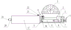
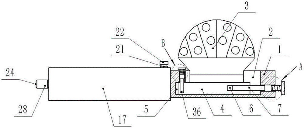
图1为一种便于安装的高效景观灯的正视剖面结构示意图。FIG. 1 is a schematic view of the front cross-sectional structure of a high-efficiency landscape light that is easy to install.
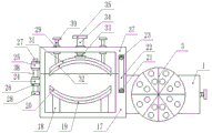
图2为一种便于安装的高效景观灯的俯视剖面结构示意图。FIG. 2 is a schematic top-view cross-sectional structure diagram of a high-efficiency landscape light that is easy to install.
图3为一种便于安装的高效景观灯中A位置的放大结构示意图。FIG. 3 is an enlarged structural schematic diagram of position A in a high-efficiency landscape light that is easy to install.
图4为一种便于安装的高效景观灯中B位置的放大结构示意图。FIG. 4 is an enlarged structural schematic diagram of position B in a high-efficiency landscape light that is easy to install.
图中:1、灯座;2、放置槽;3、高效景观灯本体;4、连接座;5、安插槽;6、第一卡槽;7、第一滑杆;8、第一滑套;9、第一通孔;10、第一弹簧;11、第一拉块;12、第二通孔;13、第二滑套;14、第二滑杆;15、第二弹簧;16、第二拉块;17、第一安装架;18、支撑杆;19、第一固定板;20、第一弹性橡胶;21、第一销轴;22、连接杆;23、第二销轴;24、第一固定块;25、第二固定块;26、第一螺纹帽;27、第二螺纹帽;28、第一拧块;29、第三滑套;30、第三滑杆;31、第二固定板;32、第二弹性橡胶;33、转轴;34、第二螺纹柱;35、第二拧块;36、第二卡槽;37、第二安装架;38、第一螺纹柱。In the figure: 1. Lamp holder; 2. Placement slot; 3. High-efficiency landscape lamp body; 4. Connection seat; 5. Installation slot; 6. First card slot; sleeve; 9, first through hole; 10, first spring; 11, first pull block; 12, second through hole; 13, second sliding sleeve; 14, second sliding rod; 15, second spring; 16 , the second pull block; 17, the first mounting frame; 18, the support rod; 19, the first fixing plate; 20, the first elastic rubber; 21, the first pin; 22, the connecting rod; 23, the second pin ; 24, the first fixed block; 25, the second fixed block; 26, the first threaded cap; 27, the second threaded cap; 28, the first screw block; 29, the third sliding sleeve; 30, the third sliding rod; 31, the second fixing plate; 32, the second elastic rubber; 33, the rotating shaft; 34, the second threaded column; 35, the second screw block; 36, the second slot; 37, the second mounting frame; 38, the first Threaded post.
具体实施方式Detailed ways
下面结合具体实施方式对本专利的技术方案作进一步详细地说明。The technical solution of the present patent will be described in further detail below in conjunction with specific embodiments.
请参阅图1-4,一种便于安装的高效景观灯,包括灯座1,所述灯座1的上表面开设有放置槽2,放置槽2内壁的左侧面开设有安插槽5;所述灯座1内壁的表面和安插槽5内壁的表面均与连接座4的表面搭接,连接座4的上表面固定连接有高效景观灯本体3,高效景观灯本体3内壁的右侧面开设有第一通孔9,第一通孔9的内壁与第一滑套8的表面固定连接,第一滑套8的内表面套接有第一滑杆7,第一滑杆7的右端与第一拉块11的左侧面固定连接,第一滑杆7的表面与第一卡槽6的内壁搭接,第一卡槽6开设在连接座4的右侧面,第一滑杆7的表面套接有第一弹簧10,第一弹簧10的两端分别与第一拉块11的左侧面和第一滑套8的右侧面固定连接,安插槽5内壁的上表面开设有第二通孔12,第二通孔12的内壁设置有第二滑套13,第二滑套13的内表面套接有第二滑杆14,第二滑杆14的顶端与第二拉块16的下表面固定连接,第二滑杆14的表面套接有第二弹簧15,第二弹簧15的两端分别与第二拉块16的下表面和第二滑套13的上表面固定连接,第二滑杆14的表面与第二卡槽36的内壁搭接,第二卡槽36开设在连接座4的上表面,通过放置槽2、安插槽5、第一滑杆7、第一滑套8、连接座4、第二滑杆14、第二滑套13、第二弹簧15、第一弹簧10、第一卡槽6和第二卡槽36之间的相互配合,使工作人员能够非常方便的将高效景观灯本体3从灯座1上取下,从而方便了工作人员对高效景观灯本体3进行检修。Please refer to FIGS. 1-4 , a high-efficiency landscape light that is easy to install, including a
所述灯座1的左侧面与第一安装架17的右侧面固定连接,第一安装架17的上表面设置有第一销轴21,第一销轴21通过连接杆22与第二销轴23活动连接,第二销轴23设置在第二安装架37的上表面,第一安装架17和第二安装架37的左侧面分别设置有第一固定块24和第二固定块25,第一固定块24的正面和第二固定块25的正面分别设置有第一螺纹帽26和第二螺纹帽27;所述第一螺纹帽26和第二螺纹帽27的内表面均与第一螺纹柱38的表面螺纹连接,通过第一螺纹柱38、第一螺纹帽26和第二螺纹帽27之间的相互配合,能够对第一安装架17和第二安装架37进行固定,第一螺纹柱38的前端与第一拧块28的背面固定连接。The left side of the
所述第一安装架17的背面与第二安装架37的正面搭接;所述第一安装架17内壁的正面通过四个支撑杆18与第一固定板19的正面固定连接,第一固定板19的背面设置有第一弹性橡胶20;所述第二安装架37的背面设置有两个第三滑套29,两个第三滑套29的内表面均套接有第三滑杆30,通过第三滑杆30和第三滑套29,使第三滑杆30在第三滑套29内上下移动时更加平稳,从而使第二固定板31通过第三滑杆30上下移动时更加平稳,第三滑杆30的两端分别与限位块的正面和第二固定板31的背面固定连接,第二固定板31的正面设置有第二弹性橡胶32,通过设置第一弹性橡胶20和第二弹性橡胶32,使第一弹性橡胶20和第二弹性橡胶32能够对树木进行保护,并且能够在与树木接触后,能够发生形变将树木卡紧;所述第二固定板31的背面设置有轴承,轴承的内表面套接有转轴33,转轴33的后端与第二螺纹柱34的前端固定连接,通过设置转轴33和轴承,使转轴33在轴承内转动时更加平稳,从而使第二螺纹柱34通过转轴33进行转动时更加平稳,第二螺纹柱34的表面螺纹连接有第三螺纹帽,第三螺纹帽卡接在第二安装架37的背面,第二螺纹帽27的后端与第二拧块35的正面固定连接。The back of the
本实用新型的工作原理是:当需要将高效景观灯本体3安装在树上时,首先打开第一安装架17和第二安装架37,并将第一安装架17和第二安装架37放置在树木表面,并使树木的表面与第一弹性橡胶20接触,再拧动第一拧块28,使第一拧块28带动第一螺纹柱38进行转动,使第一螺纹柱38与第一螺纹帽26发生螺纹运动,使第一螺纹柱38向后移动并与第二螺纹帽27螺纹连接,再拧动第二拧块35,使第二拧块35带动第二螺纹柱34进行转动,使第二螺纹柱34与第三螺纹帽发生螺纹运动,使第二螺纹柱34通过转轴33和轴承带动第二固定板31向前移动,使第二固定板31带动第二弹性橡胶32向前移动,使第二弹性橡胶32与树木接触,使第一弹性橡胶20和第二弹性橡胶32发生形变并将树木紧密贴合,从而将第一安装架17和第二安装架37固定在树木的表面。The working principle of the present invention is as follows: when the high-efficiency
当需要对高效景观灯本体3进行检修时,工作人员先拉动第二拉块16向上移动,使第二拉块16带动第二滑杆14向上移动,使第二滑杆14移出第二卡槽36,再使工作人员推动高效景观灯本体3向右移动,使高效景观灯本体3带动连接座4向右移动并移出安插槽5,从而使第一滑杆7向右移动,再使工作人员拉动第一拉块11向右移动,使第一拉块11带动第一滑杆7向右移动,使第一弹簧10伸长,使第一滑杆7移出第一卡槽6,再使工作人员将高效景观灯本体3从放置槽2内取出。When the high-efficiency
在本实用新型的描述中,需要说明的是,除非另有明确的规定和限定,术语“安装”、“相连”、“连接”应做广义理解,例如,可以是固定连接,也可以是可拆卸连接,或一体地连接;可以是机械连接,也可以是电连接;可以是直接相连,也可以通过中间媒介间接相连,可以是两个元件内部的连通。对于本领域的普通技术人员而言,可以通过具体情况理解上述术语在本实用新型中的具体含义。In the description of the present invention, it should be noted that, unless otherwise expressly specified and limited, the terms "installed", "connected" and "connected" should be understood in a broad sense, for example, it may be a fixed connection or a connectable connection. Detachable connection, or integral connection; may be mechanical connection or electrical connection; may be direct connection, or indirect connection through an intermediate medium, or internal communication between two components. For those of ordinary skill in the art, the specific meanings of the above terms in the present invention can be understood through specific situations.
上面对本专利的较佳实施方式作了详细说明,但是本专利并不限于上述实施方式,在本领域的普通技术人员所具备的知识范围内,还可以在不脱离本专利宗旨的前提下作出各种变化。The preferred embodiments of the present patent have been described in detail above, but the present patent is not limited to the above-mentioned embodiments. Within the scope of knowledge possessed by those of ordinary skill in the art, various modifications can be made without departing from the purpose of the present patent. kind of change.
Claims (5)
Priority Applications (1)
| Application Number | Priority Date | Filing Date | Title |
|---|---|---|---|
| CN201920963431.6U CN211203726U (en) | 2019-06-25 | 2019-06-25 | A high-efficiency landscape light that is easy to install |
Applications Claiming Priority (1)
| Application Number | Priority Date | Filing Date | Title |
|---|---|---|---|
| CN201920963431.6U CN211203726U (en) | 2019-06-25 | 2019-06-25 | A high-efficiency landscape light that is easy to install |
Publications (1)
| Publication Number | Publication Date |
|---|---|
| CN211203726U true CN211203726U (en) | 2020-08-07 |
Family
ID=71859958
Family Applications (1)
| Application Number | Title | Priority Date | Filing Date |
|---|---|---|---|
| CN201920963431.6U Expired - Fee Related CN211203726U (en) | 2019-06-25 | 2019-06-25 | A high-efficiency landscape light that is easy to install |
Country Status (1)
| Country | Link |
|---|---|
| CN (1) | CN211203726U (en) |
-
2019
- 2019-06-25 CN CN201920963431.6U patent/CN211203726U/en not_active Expired - Fee Related
Similar Documents
| Publication | Publication Date | Title |
|---|---|---|
| CN204853380U (en) | Tunnel illumination synthesizes and installs rack | |
| CN210601319U (en) | Ceiling lamp of scalable regulation | |
| CN205527537U (en) | Quick assembly disassembly vapour -pressure type elevating platform | |
| CN209130727U (en) | A kind of environmental protection headlamp facilitating maintenance | |
| CN212319588U (en) | Assembled LED wisdom street lamp | |
| CN218005702U (en) | Auxiliary mounting bracket for electric power engineering construction | |
| CN218819862U (en) | Campus night lamp | |
| CN209705925U (en) | Lamp mounting stand is used in a kind of road lighting construction | |
| CN211600524U (en) | Landscape street lamp convenient to inside cleanness of lamp shade | |
| CN218153801U (en) | Lighting device convenient for crown block maintenance at night | |
| CN108606483A (en) | A kind of Art Design drawing multifunctional workstation based on music system | |
| CN211475611U (en) | Exempt from installation lamp that punches | |
| CN212961038U (en) | Night lighting device is used in highway construction | |
| CN219841490U (en) | Building energy-saving exterior wall landscape lamp | |
| CN221763453U (en) | A kind of liftable induction lighting | |
| CN218442147U (en) | Wisdom lamp pole based on 5G network | |
| CN221645645U (en) | Self-lighting glass railing | |
| CN211574961U (en) | Solar street lamp with telescopic solar cell panel | |
| CN222578206U (en) | A wall-mounted ceramic candlestick | |
| CN220229014U (en) | Solar street lamp convenient to disassemble and assemble | |
| CN211372043U (en) | A new garden light that helps reduce tree pests | |
| CN218508774U (en) | A portable ceiling bracket for interior architectural decoration | |
| CN216203063U (en) | Solar street lamp for traffic engineering | |
| CN210511131U (en) | Flashlight and LED lamp bead | |
| CN213352355U (en) | A workbench for processing large-scale LED lighting devices |
Legal Events
| Date | Code | Title | Description |
|---|---|---|---|
| GR01 | Patent grant | ||
| GR01 | Patent grant | ||
| CF01 | Termination of patent right due to non-payment of annual fee | ||
| CF01 | Termination of patent right due to non-payment of annual fee |
Granted publication date: 20200807 |