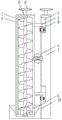
Sluice clean-up equipment for hydraulic engineering with adjustable
Technical Field
The utility model belongs to the technical field of hydraulic engineering, specifically be a sluice clean-up equipment for hydraulic engineering with adjustable.
Background
In hydraulic engineering, the adjustable gate often needs to be used, but because the gate is placed in water for a long time, some microorganisms such as green algae will be attached to the gate surface, the attractiveness of the gate is influenced, and if the gate is not cleaned for a long time, the phenomenon that the gate is corroded or damaged is easily caused, so that the service life of the gate is shortened, the common cleaning method is that workers adopt a handheld mode to go to the bottom of the gate and clean the gate by using cleaning equipment, the operation is troublesome, the potential safety hazard is high, and meanwhile, the cleaned microorganisms such as green algae are difficult to transport to the unified treatment, so that the workers are inconvenient to use, the practicability of the gate cleaning equipment is reduced, and therefore, the adjustable gate cleaning equipment for hydraulic engineering convenient to use is needed to solve the problems.
SUMMERY OF THE UTILITY MODEL
Technical problem to be solved
In order to overcome prior art's above-mentioned defect, the utility model provides a sluice cleaning equipment for hydraulic engineering with adjustable, solved because the gate is placed in aqueous for a long time, microorganism such as some green alga will be attached to the gate surface, not only influence the pleasing to the eye of gate, and if long-time not clear up just lead to the phenomenon that the sluice corrodes or damages to appear easily, thereby the life of sluice has been shortened, and general cleaning method often is that the staff adopts under the handheld mode to the sluice bottom and use cleaning equipment to clear up the sluice, not only the troublesome poeration, and the potential safety hazard is higher, still hardly transport the microorganism such as green alga that clears up simultaneously and go to unified processing, thereby inconvenient staff uses, the problem of sluice cleaning equipment's practicality has been reduced.
(II) technical scheme
In order to achieve the above object, the utility model provides a following technical scheme: the utility model provides a sluice clean-up equipment for hydraulic engineering with adjustable, includes the sluice body, this internal gate that is provided with of sluice, four first draw-in grooves have been seted up respectively to the left surface of sluice body, be provided with the fixture block in the first draw-in groove, and four fixture blocks are fixed connection respectively at the right flank of two fixed plates, and two fixed plates are fixed connection respectively at the front and the back of conveying cylinder, two upper and lower equal joints in surface of conveying cylinder inner wall have the bearing, and has cup jointed same screw axis in two bearings, four through-holes have been seted up to the surface of conveying cylinder.
The top of screw axis and the lower fixed surface that rotates the handle are connected, the conveyer drum joint is in collecting the box, collect the right flank of box and the left surface overlap joint of sluice body, and the right flank of two fixed plates is respectively through the left surface fixed connection of four telescoping devices and same scraper blade, the right-hand member of scraper blade and the left surface overlap joint of gate, the second draw-in groove has been seted up to the left surface of fixture block, be provided with fixing device in the second draw-in groove, the fixing device joint is at the left surface of sluice body, the back of conveyer drum is linked together with the front of rubbish discharge pipe.
As a further scheme of the utility model, the shape of the clamping block is L-shaped, and the shape of the first clamping groove is L-shaped.
As a further aspect of the present invention: the outer surface of the rotating handle is provided with a rubber sleeve, and the inner wall of the collecting box is provided with a trapezoidal inclined plane.
As a further aspect of the present invention: the telescopic device comprises a telescopic rod, a spring is sleeved outside the telescopic rod, and the two ends of the telescopic rod and the spring are fixedly connected with the right side face of the fixed plate and the left side face of the scraper respectively.
As a further aspect of the present invention: the fixing device comprises a bolt, the bolt is located in the second clamping groove, the bolt is in threaded connection with the nut, and the nut is connected to the left side face of the water gate body in a clamped mode.
As a further aspect of the present invention: the outer surface of the bolt is provided with a plurality of rotating blocks, and the scraper is triangular.
(III) advantageous effects
Compared with the prior art, the beneficial effects of the utility model reside in that:
1. the adjustable sluice cleaning equipment for hydraulic engineering is characterized in that through the mutual matching among the clamping blocks, the first clamping grooves, the bolts, the scraping plates, the collecting box, the through holes, the conveying cylinder, the rotating handle and the spiral shaft and the garbage discharge pipe, when the device needs to be installed, workers can firstly respectively clamp the four clamping blocks into the four first clamping grooves and move the clamping blocks downwards, so that the clamping blocks can be completely clamped into the first clamping grooves, then the four bolts are used for respectively fixing the positions of the four clamping blocks, when the gate in the gate body moves upwards, the scraping plates can scrape green algae or microorganisms adsorbed on one side of the gate in the gate body, so that the scraped green algae or microorganisms can fall into the collecting box under the action of gravity and fall into the conveying cylinder through the through holes, and then the workers rotate the spiral shaft rightwards through the rotating handle, so that the spiral shaft can drive the green algae or microorganisms in the conveying cylinder to move upwards and be discharged through the garbage discharge pipe, make this device not need the handheld cleaning equipment of staff to descend the floodgate bottom and use cleaning equipment to clear up the floodgate to can also go unified the processing with the rubbish transport under the clearance, and this device easy operation, the potential safety hazard is lower, has made things convenient for the staff to use, has improved this device's practicality.
2. This sluice cleaning equipment for hydraulic engineering rotates the handle through setting up, and is rotating the external rubber sleeve that is provided with, and the rubber material has certain antiskid nature and compliance for staff's palm when with the frictional force increase of rotation handle, rotates still can provide certain comfort level for the staff, thereby makes things convenient for the rotation of staff to the spiral shaft more.
3. This sluice cleaning equipment for hydraulic engineering through setting up telescopic link and spring for a plurality of spring can utilize the elasticity of self to drive the scraper blade always and remove right and always with this body contact of sluice, makes the green alga and the microorganism to sluice body surface that the scraper blade can be better clear up, has ensured the clearance effect, and the existence of telescopic link can be so that the scraper blade removes more stable.
Drawings
Fig. 1 is a schematic front view of a cross-sectional structure of the present invention;
fig. 2 is an enlarged schematic structural view at a position a of the present invention;
FIG. 3 is an enlarged schematic view of the structure of the utility model at B;
fig. 4 is a schematic sectional view of the top view of the present invention;
in the figure: the garbage collection device comprises a water gate body 1, a first clamping groove 2, a clamping block 3, a fixing plate 4, a conveying cylinder 5, a bearing 6, a screw shaft 7, a through hole 8, a rotating handle 9, a collection box 10, a telescopic device 11, a telescopic rod 111, a spring 112, a scraper 12, a second clamping groove 13, a fixing device 14, a bolt 141, a nut 142 and a garbage discharge pipe 15.
Detailed Description
The technical solution of the present patent will be described in further detail with reference to the following embodiments.
As shown in fig. 1-4, the utility model provides a technical scheme an adjustable sluice cleaning equipment for hydraulic engineering, including sluice body 1, be provided with the gate in the sluice body 1, four first draw-in grooves 2 have been seted up respectively to the left surface of sluice body 1, the shape of fixture block 3 is L shape, the shape of first draw-in groove 2 is L shape, through setting up first draw-in groove 2 and fixture block 3, and set up the shape of first draw-in groove 2 and fixture block 3 into L shape, make can prescribe a limit to the position of this device when fixture block 3 card goes into first draw-in groove 2 depths, thereby made things convenient for the installation of staff to this device, be provided with fixture block 3 in the first draw-in groove 2, and four fixture block 3 fixed connection are respectively at the right flank of two fixed plates 4, and two fixed plate 4 are fixed connection respectively at the front and the back of transport cylinder 5, through setting up transport cylinder 5, and set up transport cylinder 5 as netted transport cylinder 5, make transport cylinder 5 set up as rubbish transport cylinder 5, make rubbish transport cylinder 5 set up the through-hole of transport cylinder 5, make the through-hole of the transport cylinder 7 that the spiral shaft 8 stable transport cylinder 5, thereby make the spiral shaft support the spiral shaft 7 that four spiral shaft can be better, make the spiral shaft support the spiral shaft can be set up through the through-hole 8, thereby the through the rotation of spiral shaft 8, make the spiral shaft support the inner wall of spiral shaft support of four spiral shaft support the spiral shaft, make the spiral shaft support, the spiral shaft support the spiral shaft, the spiral shaft support can be better.
The top end of the spiral shaft 7 is fixedly connected with the lower surface of the rotating handle 9, the outer surface of the rotating handle 9 is provided with a rubber sleeve, the rotating handle 9 is arranged, the rubber sleeve is arranged outside the rotating handle 9, the rubber material has certain antiskid performance and flexibility, so that the rotating handle 9 can provide certain comfort for workers when the friction force between the palm of the workers and the rotating handle 9 is increased, the workers can rotate the spiral shaft 7 more conveniently, the conveying cylinder 5 is clamped in the collecting box 10, the inner wall of the collecting box 10 is provided with a trapezoidal inclined surface, green algae or microorganisms scraped by the scraping plate 12 can fall into the collecting box 10 under the action of gravity and slide into the conveying cylinder 5 through the through hole 8 under the action of the inclined surface of the collecting box 10, and the collection of the cleaned garbage by the workers is facilitated, the right side surface of the collecting box 10 is lapped with the left side surface of the sluice body 1, the right side surfaces of the two fixing plates 4 are fixedly connected with the left side surface of the same scraper 12 through four telescopic devices 11 respectively, each telescopic device 11 comprises a telescopic rod 111, a spring 112 is sleeved outside each telescopic rod 111, two ends of each telescopic rod 111 and each spring 112 are fixedly connected with the right side surface of each fixing plate 4 and the left side surface of each scraper 12 respectively, through the arrangement of the telescopic rods 111 and the springs 112, the springs 112 can drive the scraper 12 to move rightwards by utilizing the elasticity of the springs and contact with the sluice body 1 all the time, the scraper 12 can better clean green algae and microorganisms on the outer surface of the sluice body 1, the cleaning effect is ensured, the existence of the telescopic rods 111 can enable the scraper 12 to move more stably, the right end of the scraper 12 is lapped with the left side surface of the sluice body, the scraper 12 is triangular, the scraping plate 12 is triangular, so that no matter the gate ascends or descends, the triangular scraping plate 12 can clean green algae and microorganisms on the surface of the gate, the left side surface of the fixture block 3 is provided with the second clamping groove 13, the fixing device 14 is arranged in the second clamping groove 13, the fixing device 14 comprises the bolt 141, the bolt 141 is positioned in the second clamping groove 13, the bolt 141 is in threaded connection with the nut 142, the nut 142 is clamped on the left side surface of the sluice body 1, the fixing device 14 can fix the position of the fixture block 3 by arranging the fixing device 14, the device is more stable to install, the outer surface of the bolt 141 is provided with a plurality of rotating blocks, the plurality of rotating blocks are arranged outside the bolt 141, so that the friction force and the contact area between a worker and a palm of the bolt 141 can be increased, and the worker can rotate the bolt 141 more conveniently and labor-saving, the phenomenon that does not skid takes place, and fixing device 14 joint is at the left surface of sluice body 1, and the back of transport cylinder 5 is linked together with the front of rubbish discharge pipe 15, through setting up rubbish discharge pipe 15 for the staff can place a collecting vessel in rubbish discharge pipe 15 below, thereby collects the rubbish of being carried, thereby unifies the processing to rubbish.
The utility model discloses a theory of operation does:
s1, when the device needs to be installed, a worker may first respectively clamp the four fixture blocks 3 into the four first card slots 2 and move the fixture blocks 3 downward, so that the four fixture blocks 3 can be completely clamped into the four first card slots 2, and then respectively rotate the bolts 141 forward, so that the bolts 141 can move rightward under the screw connection effect with the nuts 142 and are clamped into the corresponding second card slots 13, thereby fixing the positions of the four fixture blocks 3;
s2, when the gate in the gate body moves upwards, the scraping plate 12 can scrape the green algae or microorganisms adsorbed on one side of the gate in the gate body, so that the scraped green algae or microorganisms can fall into the collecting box 10 under the action of gravity and fall into the conveying cylinder 5 through the through hole 8;
s3, the worker turns the screw shaft 7 to the right by turning the handle 9, so that the screw shaft 7 turns to drive the green algae or microorganisms in the conveying cylinder 5 to move upwards and discharge the green algae or microorganisms through the garbage discharge pipe 15.
In the description of the present invention, it is to be noted that, unless otherwise explicitly specified or limited, the terms "mounted," "connected," and "connected" are to be construed broadly, and may be, for example, fixedly connected, detachably connected, or integrally connected; can be mechanically or electrically connected; they may be connected directly or indirectly through intervening media, or they may be interconnected between two elements. The specific meaning of the above terms in the present invention can be understood by those of ordinary skill in the art through specific situations.
Although the preferred embodiments of the present patent have been described in detail, the present patent is not limited to the above embodiments, and various changes can be made without departing from the spirit of the present patent within the knowledge of those skilled in the art.