CN211136322U - A anchor clamps frock that is arranged in three-dimensional work piece cutting to produce line - Google Patents
A anchor clamps frock that is arranged in three-dimensional work piece cutting to produce line Download PDFInfo
- Publication number
- CN211136322U CN211136322U CN201921601163.XU CN201921601163U CN211136322U CN 211136322 U CN211136322 U CN 211136322U CN 201921601163 U CN201921601163 U CN 201921601163U CN 211136322 U CN211136322 U CN 211136322U
- Authority
- CN
- China
- Prior art keywords
- clamping
- fixture
- work piece
- groove
- workpiece
- Prior art date
- Legal status (The legal status is an assumption and is not a legal conclusion. Google has not performed a legal analysis and makes no representation as to the accuracy of the status listed.)
- Active
Links
Images


Abstract
The utility model relates to an anchor clamps frock that is arranged in three-dimensional work piece cutting line, including the frock platform, be provided with a plurality of clamping mechanism of group on the frock platform, set up the clamp splice that a plurality of gripped the work piece on the clamping mechanism, the clamping mechanism is including setting up the backup pad on the frock platform, and pivotal connection has locking mechanism on one side of backup pad, and locking mechanism includes pivotal connection and is in carousel in the backup pad slides on, and the carousel is provided with the connection pad, is provided with the work piece groove on the connecting plate, and the periphery in work piece groove is provided with the relative work piece groove of a plurality of clamp splice and is reciprocating motion's clamp splice. The utility model discloses a clamping device which can stably clamp a three-dimensional workpiece, and can quickly and effectively carry out multi-angle clamping and multi-angle adjustment on a plurality of vertical surfaces of the workpiece; and the multi-point positioning clamping of the workpiece is carried out by clamping different parts of the workpiece.
Description
Technical Field
The utility model relates to a machining technical field, in particular to mechanical fixture, concretely relates to anchor clamps frock that is arranged in three-dimensional work piece cutting production line.
Background
In the existing patents, the patent names: a clamping fixture for milling a machine tool upright column (patent number: CN 201320675458.8) comprises a base and fixed supporting plates arranged on the periphery of the base, wherein the base is provided with a plurality of top pieces used for keeping a workpiece to be machined on a milling working plane, the fixed supporting plates are provided with a plurality of clamping pieces used for clamping the workpiece to be machined, and a pressing piece is arranged above the workpiece to be machined.
In the prior art, a workpiece is clamped and fixed by a pair of oppositely arranged clamps, but the workpiece with a cylindrical or square or polygonal main body can be clamped by the pair of clamps, but the workpiece cannot be effectively fixed and limited. Particularly, when the three-dimensional cylinder workpiece is cut and machined, the cylinder or the three-dimensional workpiece is easy to deflect after being subjected to external force, so that machining displacement is caused, the machining precision of a product is influenced, and the product is even scrapped due to displacement during cutting and machining. While the attitude of the workpiece cannot be adjusted.
Therefore, a clamping device capable of stably clamping a three-dimensional workpiece is needed, and multi-angle clamping and multi-angle adjustment of multiple vertical surfaces of the workpiece can be rapidly and effectively performed; and the multi-point positioning clamping of the workpiece is carried out by clamping different parts of the workpiece.
SUMMERY OF THE UTILITY MODEL
The utility model overcomes the defects of the prior art, provides a clamping device which can stably clamp a three-dimensional workpiece, and can quickly and effectively carry out multi-angle clamping and multi-angle adjustment on a plurality of vertical surfaces of the workpiece; and the multi-point positioning clamping of the workpiece is carried out by clamping different parts of the workpiece.
In order to achieve the above purpose, the utility model adopts the technical scheme that: the utility model provides an anchor clamps frock for three-dimensional work piece cutting is produced line, includes the frock platform, be provided with the fixture that a plurality of group set up relatively on the frock platform, the fixture is last to set up the clamp splice of a plurality of centre gripping work piece, fixture is including setting up the backup pad on the frock platform, pivotal connection has locking mechanism on one side of backup pad, locking mechanism includes pivotal connection and is in carousel in the backup pad, be provided with the limiting plate on the carousel, be provided with the work piece groove on the limiting plate, the periphery in work piece groove is provided with a plurality of relative work piece groove and is reciprocating motion the clamp splice.
In a preferred embodiment of the present invention, a second motor is disposed on the clamping mechanism, and the second motor drives the locking mechanism to rotate.
The utility model discloses a preferred embodiment is provided with motor two on the fixture, motor two drive is connected with the driving gear, locking mechanism and driven gear fixed connection, driven gear with the driving gear is supported and is leaned on the meshing.
In a preferred embodiment of the present invention, the clamping mechanism slidably disposed on one side of the working platform is an active clamping mechanism, and the clamping mechanism fixedly disposed on the other side of the working platform is a passive clamping mechanism.
Specifically, the active clamping mechanism is arranged on a linear rail of the tool platform in a sliding mode through a sliding block arranged at the bottom of the active clamping mechanism. One side of at least one linear rail is provided with a rack, a first motor is arranged on the sliding block, a gear is connected to the first motor in a driving mode, and the gear is meshed with the rack.
The utility model discloses a preferred embodiment, be provided with the limiting plate on the carousel, be provided with the connection pad between carousel and the limiting plate, be provided with a plurality of arc draw-in grooves around the work piece groove periphery on the connection pad, be provided with the correspondence on the limiting plate the spout of arc draw-in groove.
The utility model discloses an in the preferred embodiment, the activity is provided with the connection pad between carousel and the limiting plate on the initiative fixture, is provided with a plurality of arc draw-in grooves around the work piece groove periphery on the connection pad, the embedded clamp splice that is used for the centre gripping work piece that is equipped with of arc draw-in groove, one side of fixture's carousel is provided with the cylinder, the flexible pole and the connection pad drive of cylinder are connected.
In a preferred embodiment of the present invention, one end of the clamping block is inserted into the arc-shaped slot, and the other end of the clamping block is embedded into the arc-shaped slot in the connecting pad.
In a preferred embodiment of the present invention, the clamping block is a clamping block, one end of the clamping block is provided with a clamping post, and the clamping post is embedded into the arc-shaped clamping groove; the other end of the clamping block is provided with a clamping plate, and the other end of the clamping plate penetrates through the sliding groove.
In a preferred embodiment of the present invention, the clamping block is an auxiliary clamping block, the auxiliary clamping block is slidably disposed on the connecting pad, the auxiliary clamping block is connected to the connecting pad through an elastic member, and a pivoting rod is pivotally connected to one side of the connecting pad close to the workpiece groove.
In a preferred embodiment of the present invention, a supporting seat is disposed on the tool platform between the two clamping mechanisms, and a rotating rod is pivotally connected to one side of the supporting seat against the workpiece.
According to the embodiment, the fixture tool used in the three-dimensional workpiece cutting production line has the beneficial effects that:
a clamping device for stably clamping a three-dimensional workpiece is characterized in that multi-angle clamping and multi-angle adjustment of a plurality of vertical surfaces of the workpiece are rapidly and effectively carried out; and the multi-point positioning clamping of the workpiece is carried out by clamping different parts of the workpiece.
Work piece one end is inserted from the work piece groove of the driven fixture of frock platform one side, and the supplementary clamp splice that slides on the work piece groove and set up receives the extrusion back and outwards expands, and the elastic component receives deformation, grasps the work piece.
The other end of the workpiece corresponds to a workpiece groove of the driving clamping mechanism, the driving motor drives the driving clamping mechanism to slide on the linear rail through rotation of the driving gear, so that the end part of the workpiece is inserted into the workpiece groove of the driving clamping mechanism, the air cylinder drives the connecting disc to rotate to drive the clamping block to move along the arc-shaped clamping groove, and the clamping block is driven to penetrate through a clamping plate of the sliding groove in the limiting plate to clamp the workpiece.
The second motor and the driving gear of the driven clamping mechanism and the driving clamping mechanism synchronously drive the driven gear to rotate, the locking mechanisms of the driven clamping mechanism and the driving clamping mechanism are driven to rotate by a certain angle, and the rotation of the second motor is driven according to the production requirement by adjusting the angle.
Thereby realizing the clamping of the workpiece, the adjustment of the cutting surface and the cutting angle.
Drawings
The present invention will be further explained with reference to the drawings and examples;
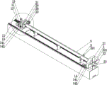
fig. 1 is a schematic structural diagram of a preferred embodiment of the present invention;
fig. 2 is a schematic top view of the preferred embodiment of the present invention;
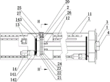
FIG. 3 is a schematic cross-sectional view of the H-H section of FIG. 2 according to a preferred embodiment of the present invention;
FIG. 4 is an enlarged, fragmentary, schematic view of FIG. 1;
FIG. 5 is an enlarged schematic view of a clamping block according to a preferred embodiment of the present invention;
in the figure: 1-a tooling platform, 11-a linear rail, 111-a sliding block, 12-a rack, 13-a motor I, 14-a motor II, 141-a brake, 142-a driving gear, 143-a driven gear, 2-a driving clamping mechanism, 20-a mounting seat, 21-a supporting plate, 22-a rotary bearing, 23-a connecting plate, 231-an arc-shaped clamping groove, 24-a limiting plate, 241-a sliding groove, 25-an air cylinder, 251-a telescopic rod, 252-a connecting block, 26-a clamping block, 261-a clamping column, 262-a clamping plate, 263-a boss, 27-a rotary table, 3-a driven clamping mechanism, 32-an auxiliary clamping block, 321-a rotary rod, 4-a workpiece and 5-a supporting seat.
Detailed Description
The invention will now be described in further detail with reference to the accompanying drawings, which are simplified schematic drawings and illustrate, by way of illustration only, the basic structure of the invention, and which therefore show only the constituents relevant to the invention.
As shown in fig. 1 to 5, a fixture tool for a three-dimensional workpiece cutting production line includes a tool platform 1, wherein two sides of the tool platform 1 are respectively provided with a driving clamping mechanism 2 slidably disposed on the tool platform 1, and a driven clamping mechanism 3 fixedly disposed on the tool platform 1. A supporting seat 5 is arranged on the tool platform 1 between the driven clamping mechanism 3 and the driving clamping mechanism 2, and the supporting seat 5 is connected with a rotating rod 321 in a pivoting mode on one side, which abuts against the workpiece 4.
In a preferred embodiment of the present invention, the active clamping mechanism 2 is slidably disposed on the linear rail 11 of the tooling platform 1 through a bottom-disposed slider 111. One side of at least one linear rail 1 is provided with a rack 12, a first motor 13 is arranged on the sliding block 111, and a gear is connected to the first motor 13 in a driving mode and meshed with the rack 12. The active clamping mechanism 2 comprises a support plate 21 which is arranged on the tool platform 1 in a sliding mode, and a locking mechanism is connected to one side of the support plate 21 in a pivoting mode. The second motor 14 is arranged on the active clamping mechanism 2, and the second motor 14 drives the locking mechanism to rotate. The second motor 14 is in driving connection with a driving gear 142, the locking mechanism is fixedly connected with a driven gear 143, and the driven gear 143 is abutted and meshed with the driving gear 142. Specifically, the locking mechanism comprises a rotary table 27 which is pivotally connected to the supporting plate 21, a limiting plate 24 is arranged on the rotary table 27, a workpiece groove is formed in the limiting plate 24, and a plurality of clamping blocks which reciprocate relative to the workpiece groove are arranged on the periphery of the workpiece groove.
More specifically, a limiting plate 24 is arranged on the turntable 27, a connecting disc 23 is arranged between the turntable 27 and the limiting plate 24, a plurality of arc-shaped clamping grooves 231 are arranged on the connecting disc 23 around the periphery of the workpiece groove, and sliding grooves 241 corresponding to the arc-shaped clamping grooves 231 are arranged on the limiting plate 24. A connecting disc 23 is movably arranged between the rotary disc 27 and the limiting plate 24 on the driving clamping mechanism 2, a plurality of arc-shaped clamping grooves 231 are arranged on the connecting disc 23 around the periphery of the workpiece groove, clamping blocks used for clamping the workpiece 4 are embedded in the arc-shaped clamping grooves 231, an air cylinder 25 is arranged on one side of the rotary disc 27 of the clamping mechanism 2, and a telescopic rod 251 of the air cylinder 25 is in driving connection with the connecting disc 23. One end of the clamping block penetrates through the arc-shaped clamping groove 231, and the other end of the clamping block is embedded into the arc-shaped clamping groove 231 in the connecting disc 23.
Furthermore, in a preferred embodiment of the present invention, the clamping block of the active clamping mechanism 2 is a clamping block 26, one end of the clamping block 26 is provided with a clamping column 261, and the clamping column 261 is embedded in the arc-shaped clamping groove 231; the other end of the clamping block 26 is provided with a clamping plate 262, and the other end of the clamping plate 262 penetrates through the sliding groove 241.
In a preferred embodiment of the present invention, the driven clamping mechanism 3 comprises a supporting plate 21 fixedly disposed on the tool platform 1, and a locking mechanism is pivotally connected to one side of the supporting plate 21. The second motor 14 is arranged on the active clamping mechanism 2, and the second motor 14 drives the locking mechanism to rotate. The second motor 14 is in driving connection with a driving gear 142, the locking mechanism is fixedly connected with a driven gear 143, and the driven gear 143 is abutted and meshed with the driving gear 142. Specifically, the locking mechanism comprises a rotary table 27 which is pivotally connected to the supporting plate 3, a limiting plate 24 is arranged on the rotary table 27, a workpiece groove is formed in the limiting plate 24, and a plurality of clamping blocks which reciprocate relative to the workpiece groove are arranged on the periphery of the workpiece groove. Specifically, the clamping block of the driven clamping mechanism 3 is an auxiliary clamping block 32, the auxiliary clamping block 32 is slidably disposed on the connecting disc 23, the auxiliary clamping block 32 is in driving connection with the connecting disc 23 through an elastic member, and a rotating rod 321 is pivotally connected to one side of the connecting disc 23 close to the workpiece groove.
The utility model discloses a theory of operation:
first, the size of the workpiece 4 to be machined is confirmed, and the workpiece 4 may be a round pipe-shaped steel material or a square pipe-shaped steel material, but is not limited thereto.
The distance between the driven clamping mechanism 3 and the driving clamping mechanism 2 is adjusted according to the size of the workpiece 4. A first motor 13 arranged on the driving clamping mechanism 2 drives a connected gear to be meshed with a rack 12 on one side of the linear rail 11, and the first motor 13 arranged on the driving clamping mechanism 2 drives the gear to rotate to drive the driving clamping mechanism 2 to slide on the linear rail 11 to a required position, so that the distance between the driven clamping mechanism 3 and the driving clamping mechanism 2 is adjusted.
Then the workpiece 4 is suspended and placed between the driven clamping mechanism 3 and the driving clamping mechanism 2. A supporting seat 5 is arranged on the tool platform 1 between the driven clamping mechanism 3 and the driving clamping mechanism 2, and the supporting seat 5 is connected with a rotating rod 321 in a pivoting manner and is used for supporting the workpiece 4, wherein the rotating rod abuts against one side of the workpiece 4.
The work piece groove of the driven fixture 3 of work piece 4 one end follow frock platform 1 one side inserts, and the supplementary clamp splice 32 that slides on the work piece groove and set up receives the extrusion back and outwards expands, and the elastic component receives deformation, grasps work piece 4.
The other end of the workpiece 4 corresponds to a workpiece groove of the driving clamping mechanism 2, the driving gear rotates through the driving motor I13 to drive the driving clamping mechanism 2 to slide on the linear rail 11, so that the end part of the workpiece 4 is inserted into the workpiece groove of the driving clamping mechanism 2, the connecting disc 23 is driven by the air cylinder 25 to rotate to drive the clamping block 26 to move along the arc-shaped clamping groove 231, and the clamping block 26 is driven to penetrate through the clamping plate 262 of the sliding groove 241 on the limiting plate 24 to clamp the workpiece 4.
The driven gear 143 is synchronously driven to rotate through the second motor 13 of the driven clamping mechanism 3 and the driving clamping mechanism 2 and the driving gear 142, the locking mechanisms of the driven clamping mechanism 3 and the driving clamping mechanism 2 are driven to rotate by a certain angle, and the rotation of the second motor 13 is driven according to the production requirement through the angle adjustment.
Thereby realizing the clamping of the workpiece 4, the adjustment of the cutting surface and the cutting angle.
In light of the foregoing, it is to be understood that various changes and modifications may be made by those skilled in the art without departing from the spirit and scope of the invention. The technical scope of the present invention is not limited to the content of the specification, and must be determined according to the scope of the claims.
Claims (10)
1. The utility model provides a fixture attachment for three-dimensional work piece cutting is produced in line, includes frock platform (1), be provided with the fixture that a plurality of group set up relatively on frock platform (1), the fixture is last to set up the clamp splice that a plurality of gripped work piece (4), its characterized in that: fixture is including setting up backup pad (21) on frock platform (1), pivotal connection has locking mechanism on one side of backup pad (21), locking mechanism includes pivotal connection and is in carousel (27) on backup pad (21), be provided with limiting plate (24) on carousel (27), be provided with the work piece groove on limiting plate (24), the periphery in work piece groove is provided with a plurality of relative work piece groove and is reciprocating motion the clamp splice.
2. The fixture tool for the three-dimensional workpiece cutting production line according to claim 1, wherein the fixture tool comprises: and a second motor (14) is arranged on the clamping mechanism, and the second motor (14) drives the locking mechanism to rotate.
3. The fixture tool for the three-dimensional workpiece cutting production line according to claim 2, wherein the fixture tool comprises: the second motor (14) is in driving connection with a driving gear (142), the locking mechanism is fixedly connected with a driven gear (143), and the driven gear (143) is abutted and meshed with the driving gear (142).
4. The fixture tool for the three-dimensional workpiece cutting production line according to claim 1, wherein the fixture tool comprises: the clamping mechanism which is arranged on one side of the tool platform (1) in a sliding mode is a driving clamping mechanism (2), and the clamping mechanism which is fixedly arranged on the other side of the tool platform (1) is a driven clamping mechanism (3).
5. The fixture tool for the three-dimensional workpiece cutting production line according to claim 4, wherein the fixture tool comprises: be provided with connection pad (23) between carousel (27) and limiting plate (24), be provided with a plurality of arc draw-in grooves (231) around work piece groove periphery on connection pad (23), be provided with on limiting plate (24) and correspond spout (241) of arc draw-in groove (231).
6. The fixture tool for the three-dimensional workpiece cutting production line according to claim 5, wherein the fixture tool comprises: the movable connection pad (23) that is provided with between carousel (27) on initiative fixture (2) and limiting plate (24), the embedded clamp splice that is used for centre gripping work piece (4) that is equipped with in arc draw-in groove (231), one side of carousel (27) of fixture (2) is provided with cylinder (25), the lift-draw pole (251) and the connection pad (23) drive of cylinder (25) are connected.
7. The fixture tool for the three-dimensional workpiece cutting production line according to claim 6, wherein the fixture tool comprises: one end of the clamping block penetrates through the arc-shaped clamping groove (231), and the other end of the clamping block is embedded into the arc-shaped clamping groove (231) in the connecting disc (23).
8. The fixture tool for the three-dimensional workpiece cutting production line according to claim 7, wherein the fixture tool comprises: the clamping block is a clamping block (26), one end of the clamping block (26) is provided with a clamping column (261), and the clamping column (261) is embedded into the arc-shaped clamping groove (231); the other end of the clamping block (26) is provided with a clamping plate (262), and the other end of the clamping plate (262) penetrates through the sliding groove (241).
9. The fixture tool for the three-dimensional workpiece cutting production line according to claim 1, wherein the fixture tool comprises: or/and the clamp block is an auxiliary clamp block (32), the auxiliary clamp block (32) is arranged on the connecting disc (23) in a sliding mode, the auxiliary clamp block (32) is connected with the connecting disc (23) through an elastic piece in a driving mode, and a rotating roller (321) is connected to one side, close to the workpiece groove, of the connecting disc (23) in a pivoting mode.
10. The fixture tool for the three-dimensional workpiece cutting production line according to claim 1, wherein the fixture tool comprises: two be provided with supporting seat (5) on frock platform (1) between the fixture, supporting seat (5) support and lean on one side pivotally connected with of work piece (4) and change rod (321).
Priority Applications (1)
| Application Number | Priority Date | Filing Date | Title |
|---|---|---|---|
| CN201921601163.XU CN211136322U (en) | 2019-09-25 | 2019-09-25 | A anchor clamps frock that is arranged in three-dimensional work piece cutting to produce line |
Applications Claiming Priority (1)
| Application Number | Priority Date | Filing Date | Title |
|---|---|---|---|
| CN201921601163.XU CN211136322U (en) | 2019-09-25 | 2019-09-25 | A anchor clamps frock that is arranged in three-dimensional work piece cutting to produce line |
Publications (1)
| Publication Number | Publication Date |
|---|---|
| CN211136322U true CN211136322U (en) | 2020-07-31 |
Family
ID=71765706
Family Applications (1)
| Application Number | Title | Priority Date | Filing Date |
|---|---|---|---|
| CN201921601163.XU Active CN211136322U (en) | 2019-09-25 | 2019-09-25 | A anchor clamps frock that is arranged in three-dimensional work piece cutting to produce line |
Country Status (1)
| Country | Link |
|---|---|
| CN (1) | CN211136322U (en) |
Cited By (1)
| Publication number | Priority date | Publication date | Assignee | Title |
|---|---|---|---|---|
| CN112453955A (en) * | 2020-11-18 | 2021-03-09 | 王小杰 | Intelligent cutting equipment based on Internet of things and used for industrial production |
-
2019
- 2019-09-25 CN CN201921601163.XU patent/CN211136322U/en active Active
Cited By (1)
| Publication number | Priority date | Publication date | Assignee | Title |
|---|---|---|---|---|
| CN112453955A (en) * | 2020-11-18 | 2021-03-09 | 王小杰 | Intelligent cutting equipment based on Internet of things and used for industrial production |
Similar Documents
| Publication | Publication Date | Title |
|---|---|---|
| CN110653631A (en) | A anchor clamps frock that is arranged in three-dimensional work piece cutting to produce line | |
| CN201900925U (en) | Multi-head stereoscopic numerical control engraver | |
| CN214108938U (en) | Multifunctional horizontal milling machine | |
| CN211249228U (en) | High-positioning milling machine | |
| CN211136322U (en) | A anchor clamps frock that is arranged in three-dimensional work piece cutting to produce line | |
| JP6777316B2 (en) | Cutting equipment | |
| CN111872717A (en) | Anchor clamps for numerical control machining | |
| CN103962840A (en) | Crankshaft turning and milling machine and tool turret for same | |
| CN113976995A (en) | Metal beveling equipment | |
| CN211333092U (en) | Workbench for hardware product production and manufacturing | |
| CN209756590U (en) | Five-axis three-dimensional engraving machine | |
| CN210161835U (en) | Five-axis three-dimensional engraving machine | |
| CN113042883B (en) | Welding engraving and milling integrated machine and use method thereof | |
| CN114799890A (en) | Turning and milling combined machining center | |
| CN115106552A (en) | Precision machining equipment for hard turning machine special-shaped alloy and working method thereof | |
| CN211840825U (en) | Positioning and rotating mechanism | |
| CN110216481B (en) | Numerical control vertical machine tool and method for processing valve body by using same | |
| CN209698114U (en) | A kind of lathe for the processing of pitman arm end face | |
| CN208468768U (en) | Double-pole library glass carving and milling machine | |
| CN215431712U (en) | Special machine tool for milling groove | |
| CN110774378A (en) | Multifunctional numerical control woodworking machine tool | |
| CN215546674U (en) | Horizontal machining center of positive T structure | |
| CN214561649U (en) | A upset anchor clamps equipment for processing of compound tenon fourth of twelve earthly branches | |
| CN219987340U (en) | Effectual automobile parts clamping device of centre gripping | |
| CN210499247U (en) | Three-dimensional plane machining center |
Legal Events
| Date | Code | Title | Description |
|---|---|---|---|
| GR01 | Patent grant | ||
| GR01 | Patent grant |