CN211122417U - A kind of concrete penetration resistance meter - Google Patents
A kind of concrete penetration resistance meter Download PDFInfo
- Publication number
- CN211122417U CN211122417U CN201921815671.8U CN201921815671U CN211122417U CN 211122417 U CN211122417 U CN 211122417U CN 201921815671 U CN201921815671 U CN 201921815671U CN 211122417 U CN211122417 U CN 211122417U
- Authority
- CN
- China
- Prior art keywords
- base
- servo motor
- sliding groove
- concrete
- penetration resistance
- Prior art date
- Legal status (The legal status is an assumption and is not a legal conclusion. Google has not performed a legal analysis and makes no representation as to the accuracy of the status listed.)
- Expired - Fee Related
Links
Images

Landscapes
- Investigating Strength Of Materials By Application Of Mechanical Stress (AREA)
Abstract
本实用新型公开了一种混凝土贯入阻力仪,涉及混凝土检测设备技术领域,旨在解决人工对检测位置进行变换时,劳动力大的技术问题,其技术方案要点是所述底座上设置有工作台,所述工作台上放置有用于存放待测混凝土的是试膜,所述底座上表面沿其长度方向开设有滑移槽,所述工作台的底壁一体成型设置有可在滑移槽内进行滑移的滑块,所述滑移槽内沿其长度方向转动设置有丝杆,所述丝杆通过滑移槽内的第一伺服电机进行驱动,所述丝杆贯穿滑块并与其螺纹连接,所述底座上设置有与第一伺服电机电连接的第一控制开关,所述第一控制开关控制第一伺服电机的开启和停止,达到了便于工人对待测物的位置进行变换,减少劳动力的优势。

The utility model discloses a concrete penetration resistance instrument, which relates to the technical field of concrete detection equipment and aims to solve the technical problem of large labor force when the detection position is changed manually. , a test film is placed on the worktable for storing the concrete to be tested, a sliding groove is opened on the upper surface of the base along its length direction, and the bottom wall of the worktable is integrally formed with a sliding groove that can be inserted into the sliding groove. For the sliding block for sliding, a screw rod is arranged in the sliding groove to rotate along its length direction. The screw rod is driven by the first servo motor in the sliding groove. The screw rod penetrates the sliding block and is threaded with it. connection, the base is provided with a first control switch electrically connected to the first servo motor, the first control switch controls the start and stop of the first servo motor, so as to facilitate the worker to change the position of the object to be measured, reduce Labor advantage.
Description
技术领域technical field
本实用新型涉及混凝土检测设备技术领域,更具体地说,它涉及一种混凝土贯入阻力仪。The utility model relates to the technical field of concrete detection equipment, in particular to a concrete penetration resistance instrument.
背景技术Background technique
混凝土贯入阻力仪是测定混凝土凝结时间的一种仪器,现有的贯入阻力仪通过把手使贯入针垂直向下运动,当贯针贯入试料模中的砼胶浆内时,胶浆对贯针产生阻力,此力通过显示装置显示出来,随着时间的增加,砼胶浆的贯入阻力相应增加,通过不同测试点测出相应的贯入阻力,获得混凝土的初凝、中凝、终凝三个状态下混凝土的强度进行检测。The concrete penetration resistance meter is an instrument for measuring the setting time of concrete. The existing penetration resistance meter moves the penetration needle vertically downward through the handle. When the penetration needle penetrates into the concrete mortar in the sample mold, the glue The mortar produces resistance to the penetration needle, and this force is displayed by the display device. With the increase of time, the penetration resistance of the concrete mortar increases accordingly, and the corresponding penetration resistance is measured through different test points to obtain the initial setting and intermediate setting of concrete. The strength of concrete under the three states of setting and final setting is tested.
现有授权公告号为CN209043753U的中国专利提供了一种混凝土贯入阻力仪,其包括底座、支架、支撑臂、支架固定在底座上,支撑臂固定在支架上,支架上还铰接有压杆,支撑臂上设置有固定头,固定头上固定设置有贯入杆,压杆与固定头顶部抵触,当需要进行检测时,工人将混凝土待测物放置到底座上,将贯入杆插入到固定头内,再实现固定,从而贯入杆竖直朝向混凝土待测物,再向下压动压杆,从而压杆抵触到固定头顶部,从而固定头挤压贯入杆向混凝土待测物移动,并贯入混凝土待测物内,实现对混凝土的检测工作。The Chinese patent with the existing authorization announcement number CN209043753U provides a concrete penetration resistance meter, which includes a base, a bracket, a support arm, and the bracket is fixed on the base, the support arm is fixed on the bracket, and a pressure rod is hinged on the bracket. A fixed head is set on the support arm, and a penetration rod is fixed on the fixed head. The pressing rod is in conflict with the top of the fixed head. When testing is required, the worker places the concrete object to be tested on the base, and inserts the penetration rod into the fixed head. In the head, it is fixed again, so that the penetration rod is vertically facing the concrete object to be measured, and then the pressure rod is pressed downward, so that the pressure rod touches the top of the fixed head, so that the fixed head squeezes the penetration rod and moves toward the concrete object to be measured. , and penetrate into the concrete to be tested to realize the detection of concrete.
但是,为了保证测试结果的准确性,工人在进行检测需要对不同位置进行至少六次测量,当前在对待测物进行移动时,均需要通过人工进行搬运,由于混凝土的重量较大,工人在搬运时十分的麻烦,劳动量较大,因此有待改善。However, in order to ensure the accuracy of the test results, workers need to measure at least six times at different positions. Currently, when moving objects to be tested, they all need to be transported manually. Due to the heavy weight of concrete, workers are carrying It is very troublesome and labor-intensive, so it needs to be improved.
实用新型内容Utility model content
针对现有技术存在的不足,本实用新型的目的在于提供一种混凝土贯入阻力仪,其具有便于工人对待测物的位置进行变换,减少劳动力的优势。Aiming at the deficiencies of the prior art, the purpose of the present invention is to provide a concrete penetration resistance meter, which has the advantages of facilitating the worker to change the position of the object to be measured and reducing labor force.
为实现上述目的,本实用新型提供了如下技术方案:To achieve the above object, the utility model provides the following technical solutions:
一种混凝土贯入阻力仪,包括底座、支架和支撑臂,所述支架固定设置在底座上,所述支撑臂固定在支架上,所述支架上铰接有压杆,所述支撑臂上设置有供压杆进行抵触的贯入杆;其特征在于:所述底座上设置有工作台,所述工作台上放置有用于存放待测混凝土的试膜,所述底座上表面沿其长度方向开设有滑移槽,所述工作台的底壁一体成型设置有可在滑移槽内进行滑移的滑块,所述滑块的外侧壁与滑移槽的内侧壁相互贴合,所述滑移槽内沿其长度方向转动设置有丝杆,所述丝杆通过滑移槽内的第一伺服电机进行驱动,所述丝杆贯穿滑块并与其螺纹连接,所述底座上设置有与第一伺服电机电连接的第一控制开关,所述第一控制开关控制第一伺服电机的开启和停止。A concrete penetration resistance meter includes a base, a support and a support arm, the support is fixed on the base, the support arm is fixed on the support, the support is hinged with a pressure rod, and the support arm is provided with The penetration rod for the pressure rod to interfere; it is characterized in that: a worktable is arranged on the base, a test film for storing the concrete to be tested is placed on the worktable, and the upper surface of the base is opened along its length direction with a A sliding groove, the bottom wall of the worktable is integrally formed with a sliding block that can slide in the sliding groove, the outer side wall of the sliding block and the inner side wall of the sliding groove are attached to each other, and the sliding A screw rod is arranged in the groove to rotate along its length direction. The screw rod is driven by the first servo motor in the sliding groove. The screw rod penetrates the slider and is threadedly connected with it. A first control switch electrically connected to the servo motor, the first control switch controls the start and stop of the first servo motor.
通过采用上述技术方案,当需要进行检测时,将试膜放置在工作台上,通过人力下压压杆,从而使贯入杆向试膜方向进行移动,并贯入试膜内的混凝土内,实现对混凝土的检测工作;当工人需要更改检测位置时,开启第一控制开关,第一伺服电机工作,第一伺服电机带动丝杆进行转动,从而滑块在丝杆上沿其长度方向进行滑动,滑块在滑移槽内进行滑动,对工作台的位置进行更换,从而对试膜的位置进行变换,无需人力对试膜进行搬运,大大减少了劳动力。By adopting the above technical solution, when testing is required, the test film is placed on the workbench, and the pressure rod is pressed down by manpower, so that the penetration rod moves in the direction of the test film and penetrates into the concrete in the test film, Realize the detection of concrete; when the worker needs to change the detection position, turn on the first control switch, the first servo motor works, and the first servo motor drives the screw to rotate, so that the slider slides on the screw along its length direction , the slider slides in the sliding groove, and the position of the worktable is replaced, so as to change the position of the test film, and the test film is not required to be transported by manpower, which greatly reduces the labor force.
进一步地,所述滑块的底壁沿其长度方向对称设置有滑轮槽,所述滑轮槽内转动设置有可与滑移槽底壁相抵的滑轮。Further, a pulley groove is symmetrically arranged on the bottom wall of the sliding block along its length direction, and a pulley that can abut against the bottom wall of the sliding groove is rotatably arranged in the pulley groove.
通过采用上述技术方案,滑轮与滑移槽底壁相抵,避免滑块底壁与滑移槽的底壁相接触,从而便于滑块在滑移槽内进行滑动,减少了第一伺服电机工作时的负荷,延长其使用寿命。By adopting the above technical solution, the pulley is abutted against the bottom wall of the sliding groove, preventing the bottom wall of the slider from contacting the bottom wall of the sliding groove, thereby facilitating the sliding of the sliding block in the sliding groove and reducing the working time of the first servo motor. load and prolong its service life.
进一步地,所述底座上沿其长度方向设置有第一刻度线。Further, the base is provided with a first scale line along its length direction.
通过采用上述技术方案,便于工人对检测位置进行记录。By adopting the above technical solution, it is convenient for workers to record the detection position.
进一步地,所述工作台上固定设置有基座,所述试膜位于基座上,所述试膜的底壁且位于其中心处固定设置有转杆,所述基座上表面开设有供转杆进行插设的转槽;所述工作台上固定设置有第二伺服电机,所述第二伺服电机的转轴与转杆之间通过同步带相连接;所述工作台上设置有与第二伺服电机电连接的第二控制开关,所述第二控制开关控制第二伺服电机的开启和停止。Further, a base is fixedly arranged on the worktable, the test film is located on the base, the bottom wall of the test film is fixedly provided with a rotating rod at its center, and the upper surface of the base is provided with a rotating rod. a rotating slot for inserting the rotating rod; a second servo motor is fixed on the worktable, and the rotating shaft of the second servo motor and the rotating rod are connected by a synchronous belt; the worktable is provided with a second servo motor The second control switch is electrically connected to the two servo motors, and the second control switch controls the start and stop of the second servo motor.
通过采用上述技术方案,开启第二控制开关,第二伺服电机工作,第二伺服电机转轴带动转杆进行转动,从而试膜在基座上进行转动,对检测位置进行进一步的跟换,扩大了对试膜内混凝土的检测范围,提高了检测效果。By adopting the above technical solution, the second control switch is turned on, the second servo motor works, and the second servo motor shaft drives the rotating rod to rotate, so that the test film is rotated on the base, and the detection position is further changed, which expands the The detection range of concrete in the test film is improved, and the detection effect is improved.
进一步地,所述基座上开设有供试膜进行插设的稳固孔,所述稳固孔的内侧壁与试膜的外侧壁相互贴合。Further, the base is provided with a stabilizing hole for inserting the test film, and the inner side wall of the stabilizing hole and the outer side wall of the test film are attached to each other.
通过采用上述技术方案,工作台在移动时,以及试膜在转动时,试膜的外侧壁与稳固孔内侧壁相贴合,试膜位于稳固孔内更加稳定。By adopting the above technical solution, when the worktable is moving and the test film is rotating, the outer side wall of the test film is abutted with the inner side wall of the stabilization hole, and the test film is more stable in the stabilization hole.
进一步地,所述稳固孔的底壁设置有环槽,所述环槽的长度方向沿稳固孔的圆周方向进行设置,所述环槽内设置有若干个与试膜底壁相抵的滚珠。Further, the bottom wall of the stabilization hole is provided with an annular groove, the length direction of the annular groove is arranged along the circumferential direction of the stabilization hole, and a plurality of balls are arranged in the annular groove against the bottom wall of the test membrane.
通过采用上述技术方案,试膜底壁与滚珠相抵,避免试膜底壁与稳固孔底壁相接触,从而便于第二伺服电机对试膜进行转动,延长了设备的使用寿命。By adopting the above technical solution, the bottom wall of the test film is abutted against the balls to avoid contact between the bottom wall of the test film and the bottom wall of the stable hole, thereby facilitating the rotation of the test film by the second servo motor and prolonging the service life of the equipment.
进一步地,所述基座上沿稳固孔的圆周方向设置有第二刻度线。Further, a second scale line is arranged on the base along the circumferential direction of the stabilization hole.
通过采用上述技术方案,进一步便于工人对混凝土的检测位置进行记录,提高了检测的精确度。By adopting the above technical solution, it is further convenient for workers to record the detection position of the concrete, and the detection accuracy is improved.
进一步地,所述试膜的外侧壁对称转动设置有把手。Further, a handle is arranged on the outer side wall of the test film to rotate symmetrically.
通过采用上述技术方案,在检测完毕后,工人拉动把手,便于对试膜进行搬运。By adopting the above technical solution, after the detection is completed, the worker pulls the handle to facilitate the handling of the test film.
综上所述,本实用新型具有以下有益效果:To sum up, the utility model has the following beneficial effects:
1、通过开启第一控制开关,第一伺服电机工作,第一伺服电机带动丝杆进行转动,从而滑块在丝杆上沿其长度方向进行滑动,滑块在滑移槽内进行滑动,对工作台的位置进行更换,从而对试膜的位置进行变换,无需人力对试膜进行搬运,大大减少了劳动力;1. By turning on the first control switch, the first servo motor works, and the first servo motor drives the screw to rotate, so that the slider slides on the screw along its length direction, and the slider slides in the sliding groove. The position of the worktable is changed, so that the position of the test film can be changed, and no manpower is required to carry the test film, which greatly reduces the labor force;
2、通过开启第二控制开关,第二伺服电机工作,第二伺服电机转轴带动转杆进行转动,从而试膜在基座上进行转动,对检测位置进行进一步的跟换,扩大了对试膜内混凝土的检测范围,提高了检测效果;2. By turning on the second control switch, the second servo motor works, and the shaft of the second servo motor drives the rotating rod to rotate, so that the test film rotates on the base, and the detection position is further changed, which expands the test film. The detection range of the inner concrete improves the detection effect;
3、通过设置在底座上的第一刻度线以及设置在基座上的第二刻度线,便于工人对混凝土的具体检测位置进行记录,提高了测量的精准度。3. Through the first scale line set on the base and the second scale line set on the base, it is convenient for workers to record the specific detection position of the concrete, and the measurement accuracy is improved.
附图说明Description of drawings
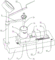
图1为实施例中一种混凝土贯入阻力仪的结构示意图;Fig. 1 is the structural representation of a kind of concrete penetration resistance meter in the embodiment;
图2为实施例中一种混凝土贯入阻力仪的剖面示意图;2 is a schematic sectional view of a concrete penetration resistance meter in an embodiment;
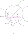
图3为图2中A部分的放大图。FIG. 3 is an enlarged view of part A in FIG. 2 .
图中:1、底座;11、支架;12、压杆;13、滑移槽;2、支撑臂;21、贯入杆;3、工作台;31、试膜;32、滑块;33、基座;4、丝杆;41、第一伺服电机;42、第一控制开关;43、第一刻度线;5、滑轮槽;51、滑轮;6、转杆;61、转槽;7、第二伺服电机;71、同步带;72、第二控制开关;73、第二刻度线;8、稳固孔;81、环槽;82、滚珠;9、把手。In the figure: 1. Base; 11. Bracket; 12. Pressing rod; 13. Sliding groove; 2. Supporting arm; 21. Penetrating rod; 3. Workbench; 31. Test film; 32. Slider; Base; 4, screw; 41, first servo motor; 42, first control switch; 43, first scale line; 5, pulley groove; 51, pulley; 6, rotating rod; 61, rotating groove; 7 71, the timing belt; 72, the second control switch; 73, the second scale line; 8, the stable hole; 81, the ring groove; 82, the ball; 9, the handle.
具体实施方式Detailed ways
以下结合附图对本实用新型作进一步详细说明。The present utility model will be described in further detail below in conjunction with the accompanying drawings.
实施例:Example:
一种混凝土贯入阻力仪,参照图1,其包括底座1、支架11和支撑臂2,支架11通过螺栓固定设置在底座1上,并且支架11与底座1相互垂直,支撑臂2通过焊接固定在支架11上,支架11上通过铰接有压杆12,支撑臂2上设置供压杆12进行抵触的贯入杆21,贯入杆21为现有技术,在此不做赘述,底座1上设置有工作台3,工作台3上放置有用于存放待测混凝土的试膜31,试膜31的横截面为圆形;当需要检测时,工人将放有待测混凝土的试膜31放置在工作台3上,下压压杆12,压杆12挤压贯入杆21向混凝土待测物移动,并贯入混凝土待测物中,实现对混凝土的检测工作,检测完毕后再反向使贯入杆21与混凝土相分离。A concrete penetration resistance meter, referring to FIG. 1, it includes a base 1, a bracket 11 and a
参照图1和图2,底座1上表面沿其长度方向开设有滑移槽13,工作台3的底壁一体成型设置有可在滑移槽13内进行滑移的滑块32,滑块32的外侧壁与滑移槽13的内侧壁相互贴合,滑移槽13内沿其长度方向转动设置有丝杆4,丝杆4的一端插设至滑移槽13内侧壁内,丝杆4的另一端连接有第一伺服电机41,第一伺服电机41通过螺栓固定设置在滑移槽13内,丝杆4贯穿滑块32并与其螺纹连接,底座1上设置有与第一伺服电机41电连接的第一控制开关42,第一控制开关42控制第一伺服电机41的开启和停止;当工人需要更改检测位置时,开启第一控制开关42,第一伺服电机41工作,第一伺服电机41带动丝杆4进行转动,从而滑块32在丝杆4上沿其长度方向进行滑动,滑块32在滑移槽13内进行滑动,对工作台3的位置进行更换,从而对试膜31的位置进行变换;底座1上沿其长度方向设置有第一刻度线43,利用第一刻度线43对滑块32在滑移槽13内的具体位置进行记录。1 and 2 , the upper surface of the base 1 is provided with a sliding
参照图2,滑块32的底壁沿其长度方向对称设置有滑轮槽5,滑轮槽5内通过转轴转动设置有可与滑移槽13底壁相抵的滑轮51,滑轮51与滑移槽13底壁相抵,避免滑块32底壁与滑移槽13的底壁相接触,从而便于滑块32在滑移槽13内进行滑动。Referring to FIG. 2 , the bottom wall of the
参照图2和图3,工作台3上通过固定设置有基座33,试膜31位于基座33上,试膜31的底壁且位于其中心处通过焊接固定设置有转杆6,基座33上表面开设有供转杆6进行插设的转槽61;工作台3上通过螺栓固定设置有第二伺服电机7,第二伺服电机7的转轴与转杆6之间通过同步带71相连接,工作台3上设置有与第二伺服电机7电连接的第二控制开关72,第二控制开关72控制第二伺服电机7的开启和停止;开启第二控制开关72,第二伺服电机7转轴带动转杆6进行转动,从而试膜31在基座33上进行转动,对检测位置进行进一步的变换,扩大了对试膜31内混凝土的检测范围。2 and 3, a
参照图2和图3,基座33上开设有供试膜31进行插设的稳固孔8,稳固孔8的内侧壁与试膜31的外侧壁相互贴合,工作台3在移动时,以及试膜31在转动时,试膜31的外侧壁与稳固孔8内侧壁相贴合,试膜31位于稳固孔8内更加稳定;稳固孔8的底壁设置有环槽81,环槽81的长度方向沿稳固孔8的圆周方向进行设置,环槽81内放置有若干个与试膜31底壁相抵的滚珠82,便于第二伺服电机7对试膜31进行转动。2 and 3, the
参照图1,基座33上沿稳固孔8的圆周方向设置有第二刻度线73,便于工人对试膜31转动后的位置进行记录,进一步提高了检测的精确度;试膜31的外侧壁对称转动设置有把手9,在检测完毕后,工人拉动把手9,便于对试膜31进行搬运。1, the
本具体实施例仅仅是对本实用新型的解释,其并不是对本实用新型的限制,本领域技术人员在阅读完本说明书后可以根据需要对本实施例做出没有创造性贡献的修改,但只要在本实用新型的权利要求范围内都受到专利法的保护。This specific embodiment is only an explanation of the present utility model, and it is not a limitation of the present utility model. Those skilled in the art can make modifications to the present embodiment without creative contribution as needed after reading this specification, but as long as the utility model is used in the present invention All new types of claims are protected by the patent law.
Claims (8)
Priority Applications (1)
| Application Number | Priority Date | Filing Date | Title |
|---|---|---|---|
| CN201921815671.8U CN211122417U (en) | 2019-10-28 | 2019-10-28 | A kind of concrete penetration resistance meter |
Applications Claiming Priority (1)
| Application Number | Priority Date | Filing Date | Title |
|---|---|---|---|
| CN201921815671.8U CN211122417U (en) | 2019-10-28 | 2019-10-28 | A kind of concrete penetration resistance meter |
Publications (1)
| Publication Number | Publication Date |
|---|---|
| CN211122417U true CN211122417U (en) | 2020-07-28 |
Family
ID=71701182
Family Applications (1)
| Application Number | Title | Priority Date | Filing Date |
|---|---|---|---|
| CN201921815671.8U Expired - Fee Related CN211122417U (en) | 2019-10-28 | 2019-10-28 | A kind of concrete penetration resistance meter |
Country Status (1)
| Country | Link |
|---|---|
| CN (1) | CN211122417U (en) |
Cited By (3)
| Publication number | Priority date | Publication date | Assignee | Title |
|---|---|---|---|---|
| CN112903532A (en) * | 2021-03-13 | 2021-06-04 | 杭州市交通工程试验检测中心有限公司 | Pitch penetration tester |
| CN112964601A (en) * | 2021-02-06 | 2021-06-15 | 青岛建一混凝土有限公司 | Concrete penetration resistance instrument |
| CN112986057A (en) * | 2021-01-29 | 2021-06-18 | 广州市瀚源建设工程质量检测有限公司 | Strength detection device of concrete penetration resistance instrument |
-
2019
- 2019-10-28 CN CN201921815671.8U patent/CN211122417U/en not_active Expired - Fee Related
Cited By (3)
| Publication number | Priority date | Publication date | Assignee | Title |
|---|---|---|---|---|
| CN112986057A (en) * | 2021-01-29 | 2021-06-18 | 广州市瀚源建设工程质量检测有限公司 | Strength detection device of concrete penetration resistance instrument |
| CN112964601A (en) * | 2021-02-06 | 2021-06-15 | 青岛建一混凝土有限公司 | Concrete penetration resistance instrument |
| CN112903532A (en) * | 2021-03-13 | 2021-06-04 | 杭州市交通工程试验检测中心有限公司 | Pitch penetration tester |
Similar Documents
| Publication | Publication Date | Title |
|---|---|---|
| CN205449659U (en) | Novel hardness test centre gripping device | |
| CN105784521B (en) | A kind of full-automatic injection resistance meter of concrete and setting time measurement method | |
| CN200993567Y (en) | Thickness measuring equipment | |
| CN105698723B (en) | A kind of bearing rotation precision automatic detection device | |
| CN205593868U (en) | Full -automatic penetration resistance appearance of concrete | |
| CN105973707B (en) | A kind of bearing cage rivet breakaway force NC inspecting equipment | |
| CN204535630U (en) | A kind of sample parallel degree proving installation | |
| CN203719597U (en) | Door hinge gap and angle measurement detecting tool | |
| CN205352836U (en) | Universal anchor clamps are used in test of out -of -shape sample vickers hardness | |
| CN108534836B (en) | Automatic detection device and method for cylindrical rock sample | |
| CN220625077U (en) | Detection device is used in production of thin wall cylinder liner | |
| CN217764764U (en) | Measuring tool detection device | |
| CN207866642U (en) | Wear detector for bottom pivot mushroom head | |
| CN212843466U (en) | Bearing ring size detection equipment | |
| CN212030365U (en) | A kind of tool spiral groove runout detection mechanism | |
| CN219607873U (en) | Steel tape verification platform machine | |
| CN219737210U (en) | Penetrometer for quality detection of building engineering | |
| CN218469742U (en) | Hole center detection device convenient to detect | |
| CN206208679U (en) | A Martindale Friction Tester | |
| CN110779426A (en) | A bearing roundness and concentricity measuring device | |
| CN207147736U (en) | Pressure tester | |
| CN208042943U (en) | Portable concrete thickness gauge | |
| CN208026559U (en) | A kind of material static(al) stretching RTA reliability test assembly | |
| CN209802324U (en) | flatness detector | |
| CN211527278U (en) | A ball cage channel diameter measuring instrument |
Legal Events
| Date | Code | Title | Description |
|---|---|---|---|
| GR01 | Patent grant | ||
| GR01 | Patent grant | ||
| CF01 | Termination of patent right due to non-payment of annual fee | ||
| CF01 | Termination of patent right due to non-payment of annual fee |
Granted publication date: 20200728 |