CN211117677U - Electric angle seat valve - Google Patents
Electric angle seat valve Download PDFInfo
- Publication number
- CN211117677U CN211117677U CN201922384689.3U CN201922384689U CN211117677U CN 211117677 U CN211117677 U CN 211117677U CN 201922384689 U CN201922384689 U CN 201922384689U CN 211117677 U CN211117677 U CN 211117677U
- Authority
- CN
- China
- Prior art keywords
- sealing
- spring
- valve
- ring group
- valve rod
- Prior art date
- Legal status (The legal status is an assumption and is not a legal conclusion. Google has not performed a legal analysis and makes no representation as to the accuracy of the status listed.)
- Active
Links
- 238000007789 sealing Methods 0.000 claims abstract description 246
- 230000006835 compression Effects 0.000 claims abstract description 12
- 238000007906 compression Methods 0.000 claims abstract description 12
- 238000000034 method Methods 0.000 claims description 3
- 230000008569 process Effects 0.000 claims description 3
- 230000000694 effects Effects 0.000 abstract description 20
- 239000012530 fluid Substances 0.000 description 3
- 230000008602 contraction Effects 0.000 description 2
- 238000009434 installation Methods 0.000 description 2
- 239000013589 supplement Substances 0.000 description 2
- 230000009471 action Effects 0.000 description 1
- 230000002238 attenuated effect Effects 0.000 description 1
- 230000009286 beneficial effect Effects 0.000 description 1
- 230000008859 change Effects 0.000 description 1
- 230000008878 coupling Effects 0.000 description 1
- 238000010168 coupling process Methods 0.000 description 1
- 238000005859 coupling reaction Methods 0.000 description 1
- 230000004044 response Effects 0.000 description 1
- XLYOFNOQVPJJNP-UHFFFAOYSA-N water Substances O XLYOFNOQVPJJNP-UHFFFAOYSA-N 0.000 description 1
Images

Landscapes
- Lift Valve (AREA)
Abstract
The utility model relates to an electric angle seat valve, a valve rod sequentially passes through a second sealing cap, a second sealing ring group, a second sealing flat gasket, a first sealing ring group, a sealing sleeve, a first sealing connecting cap and a valve core; a third sealing spring in a compressed state is arranged in the sealing pipe, a grid is arranged in the area, located in the sealing pipe, of the valve rod, a first sealing spring and a second sealing spring are arranged on two sides of the grid of the valve rod respectively, and the first sealing spring is located between the second sealing flat gasket and the grid; the utility model discloses strengthen waterproof electronic angle seat valve, third sealing spring both ends are pressed respectively and are supported second sealed flat gasket and first sealed flat gasket, continue to make first sealing washer group and second sealing washer group warp and produce sealed effect; when the valve rod stretches out and draws back, the check keep off and make second sealing spring or first sealing spring be in high compression state, guarantee one side produce a strong sealed effect.
Description
Technical Field
The utility model belongs to angle seat valve structure field, concretely relates to electronic angle seat valve.
Background
The angle seat valve is widely applied, is particularly suitable for valves which frequently act in a short time, and has the characteristics of sensitive response and accurate action. Prior art angle seat valves include manual angle seat valves and pneumatic angle seat valves.
The sealing of the valve rod always has an internal and external expanding force in the sealing ring through the spring, so that the valve rod is not leaked. The sealing ring is generally a rubber ring with a V-shaped section. However, the spring force of the spring is attenuated at all times, so that the sealing performance of the angle seat valve is necessarily reduced. In the case of an electric angle seat valve, if a water leakage occurs, there is a risk of electric leakage.
SUMMERY OF THE UTILITY MODEL
The utility model aims at overcoming the technical problem who exists among the above-mentioned background art, providing an electronic angle seat valve.
In order to achieve the technical purpose, the utility model adopts the following technical scheme:
an electric angle seat valve comprises a valve seat, a first sealing connection cap, a sealing pipe, a second sealing cap and a valve rod.
The first sealing connection cap is connected with the valve seat through threaded fit, the sealing pipe is connected with the free end of the first sealing connection cap through threaded fit, and the second sealing cap is connected with the free end of the sealing pipe through threaded fit; the function of the sealing tube is to form an enhanced sealing effect compared with the conventional electric angle seat valve. The second sealing cap is connected with a motor part, a rotating shaft of the motor is connected with the valve rod through a coupler, and the motor drives the valve rod to stretch.
The sealing device is characterized in that a sealing sleeve and a first sealing ring group are sequentially arranged in the first sealing connecting cap, a first sealing flat gasket is arranged on the first sealing ring group in a pressing mode, a second sealing ring group is arranged in the second sealing cap, and a second sealing flat gasket is arranged on the second sealing ring group in a pressing mode.
The valve rod sequentially penetrates through the second sealing cap, the second sealing ring group, the second sealing flat gasket, the first sealing ring group, the sealing sleeve, the first sealing connecting cap and the valve core.
A third sealing spring in a compressed state is arranged in the sealing pipe, and the outer diameter of the third sealing spring is equal to the inner diameter of the sealing pipe; the compressed state of the third sealing spring is not changed along with the expansion and contraction of the valve rod. One end of the third sealing spring presses against the second sealing flat gasket to enable the second sealing ring set to deform to generate a sealing effect, and the other end of the third sealing spring presses against the first sealing flat gasket to enable the first sealing ring set to deform to generate a sealing effect. Even if the first sealing ring group and the sealing sleeve have poor sealing, the second sealing ring group and the second sealing flat gasket can also prevent fluid from entering the end of the motor.
A grid block is arranged in the area, located on the sealing pipe, of the valve rod, and a first sealing spring and a second sealing spring are arranged on two sides of the grid block of the valve rod respectively; the inner diameters of the first sealing spring and the second sealing spring are equal to the outer diameter of the valve rod; the first sealing spring is located between the second sealing flat gasket and the grid block, the second sealing spring is located between the first sealing flat gasket and the grid block, and the first sealing spring and the second sealing spring are always in a compressed state in the vertical movement process of the valve rod. When the valve rod moves towards the valve seat, the check block compresses the second sealing spring, the second sealing spring is in a high compression state, and the sealing effect of the first sealing flat gasket and the first sealing ring group is greatly enhanced. When the valve rod is far away from the valve seat and moves, the check block compresses the first sealing spring, the first sealing spring is in a high compression state, and the sealing effect of the second sealing flat gasket and the second sealing ring group is greatly enhanced. When the third sealing spring can not provide a good sealing effect, the first sealing spring and the second sealing spring can supplement a strong sealing effect.
Preferably, the sections of the sealing ring units of the second sealing ring group and the first sealing ring group are both in a V shape, so that the sealing effect of the inner ring and the outer ring of the sealing ring unit is increased simultaneously.
Preferably, when the block is located in the middle of the sealing tube, the compression states of the first sealing spring and the second sealing spring are consistent, so that the installation is convenient on one hand, and at least one of the first sealing spring and the second sealing spring can be kept in a high compression state on the other hand.
The utility model provides an electronic angle seat valve has following beneficial effect:
1. even if the first sealing ring group and the sealing sleeve have poor sealing, the second sealing ring group and the second sealing flat gasket can also prevent fluid from entering the end of the motor;
2. two ends of the third sealing spring are pressed against the second sealing flat gasket and the first sealing flat gasket respectively, and the first sealing ring group and the second sealing ring group are continuously deformed to generate a sealing effect;
3. when the valve rod stretches out and draws back, the check keep off and make second sealing spring or first sealing spring be in high compression state, guarantee one side produce a strong sealed effect.
Drawings
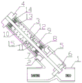
Fig. 1 is a schematic sectional structure view of the electric angle seat valve in a closed state;
fig. 2 is a schematic cross-sectional view of the electric angle seat valve according to the present invention in an open state;
reference numerals: the valve seat (1), the first sealing connection cap (2), the sealing tube (3), the second sealing cap (4), the valve rod (5), the valve core (6), the sealing sleeve (7), the first sealing ring group (8), the first sealing flat gasket (9), the first sealing spring (10), the second sealing spring (11), the third sealing spring (12), the second sealing flat gasket (13), the second sealing ring group (14) and the grid block (15).
Detailed Description
The technical solution of the present invention will be described in detail with reference to the accompanying drawings and specific embodiments.
As shown in fig. 1-2, the electric angle seat valve comprises a valve seat 1, a first sealing connection cap 2, a sealing pipe 3, a second sealing cap 4 and a valve rod 5.
The first sealing connection cap 2 is connected with the valve seat 1 through thread matching, the sealing pipe 3 is connected with the free end of the first sealing connection cap 2 through thread matching, and the second sealing cap 4 is connected with the free end of the sealing pipe 3 through thread matching; the function of the sealing tube 3 is to form an enhanced sealing effect compared with the conventional electric angle seat valve. The second sealing cap 4 is connected to a motor part (not shown), a rotating shaft (not shown) of the motor is connected to the valve rod 5 through a coupling (not shown), and the motor drives the valve rod 5 to extend and retract.
The sealing device is characterized in that a sealing sleeve 7 and a first sealing ring group 8 are sequentially arranged in the first sealing connecting cap 2, a first sealing flat gasket 9 is arranged on the first sealing ring group 8 in a pressing mode, a second sealing ring group 14 is arranged in the second sealing cap 4, and a second sealing flat gasket 13 is arranged on the second sealing ring group 14 in a pressing mode.
The valve rod 5 sequentially passes through the second sealing cap 4, the second sealing ring group 14, the second sealing flat gasket 13, the first sealing flat gasket 9, the first sealing ring group 8, the sealing sleeve 7, the first sealing connecting cap 2 and the valve core 6.
A third sealing spring 12 in a compressed state is arranged in the sealing tube 3, and the outer diameter of the third sealing spring 12 is equal to the inner diameter of the sealing tube 3; the compressed state of the third seal spring 12 does not change with the expansion and contraction of the valve stem 5. One end of the third sealing spring 12 presses against the second flat sealing pad 13 so as to deform the second sealing ring group 14 to generate a sealing effect, and the other end of the third sealing spring 12 presses against the first flat sealing pad 9 so as to deform the first sealing ring group 8 to generate a sealing effect. Even if the first sealing ring group 8 and the sealing sleeve 7 have poor sealing, the second sealing ring group 14 and the second sealing flat gasket 13 can prevent fluid from entering the end of the motor.
A grid block 15 is arranged in the area, located on the sealing tube 3, of the valve rod 5, and a first sealing spring 10 and a second sealing spring 11 are respectively arranged on two sides of the grid block 15 of the valve rod 5; the inner diameters of the first sealing spring 10 and the second sealing spring 11 are equal to the outer diameter of the valve rod 5; the first sealing spring 10 is located between the second sealing flat gasket 13 and the grid baffle 15, the second sealing spring 11 is located between the first sealing flat gasket 9 and the grid baffle 15, and the first sealing spring 10 and the second sealing spring 11 are always in a compressed state in the vertical movement process of the valve rod 5. When the valve rod 5 moves towards the valve seat 1, the grid block 15 compresses the second sealing spring 11, the second sealing spring 11 is in a high compression state, and the sealing effect of the first sealing flat gasket 9 and the first sealing ring group 8 is greatly enhanced. When the valve rod 5 moves away from the valve seat 1, the grid 15 compresses the first sealing spring 10, the first sealing spring 10 is in a high compression state, and the sealing effect of the second sealing flat gasket 13 and the second sealing ring group 14 is greatly enhanced. When the third seal spring 12 cannot provide a good sealing effect, the first seal spring 10 and the second seal spring 11 can supplement a strong sealing effect.
The sections of the sealing ring units of the second sealing ring group 14 and the first sealing ring group 8 are both V-shaped, so that the sealing effect of the inner ring and the outer ring of the sealing ring unit is increased simultaneously.
When the block 15 is located in the middle of the sealing tube 3, the compression states of the first sealing spring 10 and the second sealing spring 11 are consistent, so that the installation is convenient on one hand, and at least one of the first sealing spring 10 and the second sealing spring 11 can be kept in a high compression state on the other hand.
The use of "first," "second," and similar terms in the description and in the claims does not indicate any order, quantity, or importance, but rather is used to distinguish one element from another. Also, the use of the terms "a," "an," or "the" and similar referents do not denote a limitation of quantity, but rather denote the presence of at least one. The word "comprise" or "comprises", and the like, means that the element or item listed before "comprises" or "comprising" covers the element or item listed after "comprising" or "comprises" and its equivalents, and does not exclude other elements or items. "upper", "lower", "left", "right", and the like are used merely to indicate relative positional relationships, and when the absolute position of the object being described is changed, the relative positional relationships may also be changed accordingly.
The embodiment is only a single implementation manner of the present invention, and for those skilled in the art, other embodiments can be obtained according to the attached drawings without any creative effort, and are also within the protection scope of the present invention.
Claims (3)
1. The utility model provides an electronic angle seat valve, includes disk seat, first sealed connection cap, sealed pipe, the sealed cap of second and valve rod, its characterized in that:
the first sealing connection cap is connected with the valve seat through threaded fit, the sealing pipe is connected with the free end of the first sealing connection cap through threaded fit, and the second sealing cap is connected with the free end of the sealing pipe through threaded fit;
a sealing sleeve and a first sealing ring group are sequentially arranged in the first sealing connecting cap,
a first sealing flat gasket is arranged on the first sealing ring group in a pressing mode, a second sealing ring group is arranged in the second sealing cap, and a second sealing flat gasket is arranged on the second sealing ring group in a pressing mode;
the valve rod sequentially passes through the second sealing cap, the second sealing ring group, the second sealing flat gasket, the first sealing ring group, the sealing sleeve, the first sealing connecting cap and the valve core;
a third sealing spring in a compressed state is arranged in the sealing pipe, and the outer diameter of the third sealing spring is equal to the inner diameter of the sealing pipe;
a grid block is arranged in the area, located on the sealing pipe, of the valve rod, and a first sealing spring and a second sealing spring are arranged on two sides of the grid block of the valve rod respectively; the inner diameters of the first sealing spring and the second sealing spring are equal to the outer diameter of the valve rod; the first sealing spring is located between the second sealing flat gasket and the grid baffle, the second sealing spring is located between the first sealing flat gasket and the grid baffle, and the first sealing spring and the second sealing spring are always in a compression state in the telescopic process of the valve rod.
2. The electric angle seat valve as claimed in claim 1, wherein the sealing ring units of the second sealing ring group and the first sealing ring group are both V-shaped in cross section.
3. The electric angle seat valve according to claim 1 or 2, characterized in that when the grid is located in the middle of the sealing tube, the valve core is in the closed position of the valve seat, and the compression states of the first sealing spring and the second sealing spring are consistent.
Priority Applications (1)
| Application Number | Priority Date | Filing Date | Title |
|---|---|---|---|
| CN201922384689.3U CN211117677U (en) | 2019-12-26 | 2019-12-26 | Electric angle seat valve |
Applications Claiming Priority (1)
| Application Number | Priority Date | Filing Date | Title |
|---|---|---|---|
| CN201922384689.3U CN211117677U (en) | 2019-12-26 | 2019-12-26 | Electric angle seat valve |
Publications (1)
| Publication Number | Publication Date |
|---|---|
| CN211117677U true CN211117677U (en) | 2020-07-28 |
Family
ID=71698810
Family Applications (1)
| Application Number | Title | Priority Date | Filing Date |
|---|---|---|---|
| CN201922384689.3U Active CN211117677U (en) | 2019-12-26 | 2019-12-26 | Electric angle seat valve |
Country Status (1)
| Country | Link |
|---|---|
| CN (1) | CN211117677U (en) |
-
2019
- 2019-12-26 CN CN201922384689.3U patent/CN211117677U/en active Active
Similar Documents
| Publication | Publication Date | Title |
|---|---|---|
| CN210890533U (en) | Hydraulic quick joint with good sealing effect | |
| CN201434173Y (en) | Super-high pressure quick connector | |
| CN201246554Y (en) | Corrugated tube joint | |
| CN207569433U (en) | A kind of closeouts for hot-water heating PPR pipe | |
| CN202972300U (en) | Ultrahigh pressure detachable cone sealing pressure-measuring connector | |
| CN210716138U (en) | Double-ball non-return joint with good sealing performance | |
| CN205001756U (en) | Pipeline rapid repairing device | |
| CN201757175U (en) | Tapered piece ring sealing device | |
| CN209557837U (en) | A kind of drainage system pipe that air-tightness is good | |
| CN207394163U (en) | A kind of hydraulic pipeline joint component | |
| CN214579435U (en) | Quick coupling with good connecting effect | |
| CN204692849U (en) | A kind of bellows Quick connection part | |
| CN205244729U (en) | Pipeline leak test closing device | |
| CN208670334U (en) | A kind of three-way pipeline connector | |
| CN2479333Y (en) | Leak-proof pipe fitting | |
| CN203797064U (en) | Novel joint check valve | |
| CN203036136U (en) | High pressure detachable type ball sealing pressure measuring connector | |
| CN2381871Y (en) | Plastic pipe joint | |
| CN211258703U (en) | Telescopic pipe for gas drainage in coal mine | |
| CN209444932U (en) | A kind of New type corrugated pipe coupling component and connection structure | |
| CN205136667U (en) | Ball valve | |
| CN214224441U (en) | Air conditioner pipe sealing test device | |
| CN201412626Y (en) | Multipurpose plastic pipe connecting tube | |
| CN222963106U (en) | Leakage-proof mechanism of hydraulic cylinder | |
| CN201090868Y (en) | Large deflection expansion joint |
Legal Events
| Date | Code | Title | Description |
|---|---|---|---|
| GR01 | Patent grant | ||
| GR01 | Patent grant |