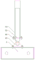
Four-leg structure of bridge girder erection machine capable of lifting height without limitation
Technical Field
The utility model relates to a bridge crane machinery technical field especially relates to a four landing leg structures of bridge crane of unrestricted lifting height.
Background
The bridge girder erection machine is equipment for placing prefabricated beam pieces on a prefabricated bridge pier. The bridge girder erection machine belongs to the category of cranes, because the main function of the bridge girder erection machine is to lift a beam piece and then transport the beam piece to a place and then put down, but the bridge girder erection machine is different from a general crane in a large sense, the required conditions are harsh, and the bridge girder erection machine runs on the beam piece or is called longitudinal movement. The bridge girder erection machine is divided into a plurality of bridge girders for erecting highway bridges, conventional railway bridges, special passenger railway bridges and the like. Along with the development of high-speed railways and highways, the erection problem of large-tonnage prefabricated whole-hole box girders is more prominent, various large box girder bridge erecting machines appear at home and abroad, the conventional bridge erecting machine is usually lifted and lowered by adopting a segmental upright post to adjust the gradient of a foundation, the adaptability to the erection requirements of different gradients is poor, the erection construction range under the condition of longitudinal gradient is small, the stability is poor, the integral quality is large, and the inconvenience is brought to operators.
SUMMERY OF THE UTILITY MODEL
The utility model discloses a solve prior art's weak point and provide a four landing leg structures of bridge girder erection machine of unlimited lifting height to be applicable to the building site construction and to the requirement of setting up of different slopes, improved the stability of bridge girder erection machine.
The utility model discloses a solve the technical scheme that the construction requirement of different slopes provided, provide a four landing leg structures of bridge crane that unrestricted lifting height, including the bottom end rail, the bottom of bottom end rail is equipped with the running gear that the symmetry set up, and running gear includes the wheel case, and the top and the bottom end rail of wheel case are articulated, are equipped with the walking wheel that the symmetry set up in the wheel case, and the outside of wheel case is fixed with three-phase asynchronous machine, and three-phase asynchronous machine's transmission output shaft end connection reduction gear, the output and the walking wheel transmission of reduction gear are connected. The both ends of bottom end rail are equipped with the landing leg before the frame bridge machine of symmetry respectively, and the vertical upper end of fixing at the bottom end rail of landing leg before the frame bridge machine, the landing leg includes the support column that two parallel intervals set up before the frame bridge machine, set up the mounting hole that even interval set up on the support column, the mounting hole symmetry on two support columns sets up. The bottom of support column is equipped with the landing leg base, and two support columns pass through the landing leg flange and vertically fix respectively on the landing leg base. The bottom mounting of landing leg base has the upper leg pipe of vertical setting, is fixed with angle adjustable on the upper leg pipe and goes up the carousel, and the both ends symmetry of bottom end rail is fixed with the lower leg pipe of vertical setting, and the top of lower leg pipe is fixed with angle adjustable's lower carousel, goes up carousel and lower carousel fixed connection. The upper end of the support column is provided with a hydraulic cylinder joist, the hydraulic cylinder joist is provided with a joist pin shaft tube, the two ends of the hydraulic cylinder joist are symmetrically provided with through holes for mounting the joist pin shaft tube, the joist pin shaft tube is respectively fixed in the through holes, the two ends of the hydraulic cylinder joist and the joist pin shaft tube are respectively provided with symmetrical mounting holes, and the two ends of the hydraulic cylinder joist are respectively detachably assembled on the support column through pin shafts. A hydraulic cylinder supporting seat is sleeved in the middle of the hydraulic cylinder joist, a hydraulic cylinder hinge seat plate is fixed at the top end of the hydraulic cylinder supporting seat, a vertically arranged hydraulic cylinder is hinged on the hydraulic cylinder hinge seat plate, and the free end of the hydraulic cylinder is hinged with the hydraulic cylinder hinge seat plate; the hydraulic cylinder supporting beam is characterized in that a main beam supporting beam is arranged above the hydraulic cylinder supporting beam, two ends of the main beam supporting beam are respectively detachably assembled on the supporting columns, a supporting beam pin shaft tube is arranged on the main beam supporting beam, through holes for installing the supporting beam pin shaft tube are symmetrically formed in two ends of the main beam supporting beam, the supporting beam pin shaft tube is fixed in the through holes, a supporting beam sliding sleeve is fixed at the bottom end of the supporting beam pin shaft tube, installing holes are also formed in the supporting beam sliding sleeve, and the supporting beam sliding sleeve is respectively fixed on the supporting columns through pin shafts. The hydraulic cylinder placing pipe is fixed on the main beam joist, a hydraulic cylinder flange is fixed at the bottom end of the hydraulic cylinder placing pipe, the hydraulic cylinder is assembled in the hydraulic cylinder placing pipe, and the fixed end of the hydraulic cylinder is fixed with the main beam joist through the hydraulic cylinder flange. The top end of the girder joist is fixed with a main girder of the bridge girder erection machine, an upper crossbeam is arranged between the two main girders of the bridge girder erection machine, and two ends of the upper crossbeam are respectively fixed on the two main girders of the bridge girder erection machine.
Preferably, the upper turntable and the lower turntable are respectively and symmetrically provided with mounting holes which are uniformly arranged at intervals, the upper turntable and the lower turntable are circumferentially and uniformly provided with fixing ribs at intervals, and the fixing ribs are respectively fixed between the two mounting holes. .
Preferably, two ends of the lower cross beam are respectively symmetrically provided with a plurality of groups of mounting holes, and the lower support leg pipes are assembled in the mounting holes; the upper cross beam is a telescopic beam.
Preferably, the top end of the main beam of the bridge erecting machine is respectively fixed with a trolley track, the end part of the trolley track is provided with a limiting block, and the limiting block is fixed on the main beam of the bridge erecting machine.
Adopt above-mentioned technical scheme, the utility model has the advantages of it is following:
1. the hydraulic cylinders arranged on the hydraulic cylinder joists can adjust the height of the main girder joists of the bridge girder erection machine according to different construction conditions, the hydraulic cylinder joists are fixed by the pin shafts during adjustment, then the pin shafts on the main girder joists are pulled down, the hydraulic cylinders on the two hydraulic cylinder joists are started simultaneously, and the hydraulic cylinders drive the main girder joists to move upwards to the designated position. Thereby realizing that the trolley track on the main beam of the bridge erecting machine is lifted to a certain height.
2. The upper beam and the lower beam are adjustable telescopic beams, and the length of the upper beam and the length of the lower beam can be adjusted according to different working conditions, so that the requirements of different constructions of construction sites are met.
3. The upper rotary table and the lower rotary table with adjustable angles can adjust the bridge girder erection machine by a certain angle according to the requirements of different construction working conditions, and are applicable to the construction engineering of the inclined bridge girder erection.
Drawings
Fig. 1 is a first schematic structural diagram of the present invention;
FIG. 2 is a second schematic structural view of the present invention;
FIG. 3 is a schematic structural view of a hydraulic cylinder joist and a main girder joist;
FIG. 4 is a schematic structural view of a front leg of the bridge girder erection machine;
FIG. 5 is a schematic view of a hydraulic cylinder joist structure;
FIG. 6 is a schematic view of a hydraulic cylinder structure;
FIG. 7 is a schematic structural view of an upper leg tube and a lower leg tube;
fig. 8 is a schematic structural diagram of the upper turntable.
Reference numerals: 1. a lower cross beam; 2. a traveling mechanism; 3. front support legs of the bridge girder erection machine; 4. a hydraulic cylinder joist; 5. a main beam joist; 6. a main beam of the bridge erecting machine; 7. an upper cross beam; 21. a wheel box; 22. a traveling wheel; 23. a three-phase asynchronous motor; 31. a support pillar; 32. a leg base; 33. a leg flange; 34. an upper leg tube; 35. a lower leg pipe; 36. an upper turntable; 37. a lower turntable; 38. fixing the ribs; 41. a joist pin shaft tube; 42. a hydraulic cylinder supporting seat; 43. a hydraulic cylinder hinge seat plate; 44. a hydraulic cylinder; 51. a joist sliding sleeve; 52. placing a pipe in the hydraulic cylinder; 53. a hydraulic cylinder flange; 61. a main beam flange; 62. a trolley track; 63. a limiting block; 64. and (7) a pin shaft.
Detailed Description
As shown in fig. 1-8, the utility model relates to a four landing leg structures of bridge crane of unrestricted lifting height, including bottom end rail 1, the bottom of bottom end rail 1 is equipped with the running gear 2 that the symmetry set up, running gear 2 includes wheel box 21, and the top of wheel box 21 is articulated with bottom end rail 1, is equipped with the walking wheel 22 that the symmetry set up in the wheel box 21, and the outside of wheel box 21 is fixed with three-phase asynchronous motor 23, and three-phase asynchronous motor 23's transmission output shaft end connection reduction gear, the output and the walking wheel 22 transmission of reduction gear are connected. The both ends of bottom end rail 1 are equipped with the front leg 3 of the bridge girder erection machine of symmetry respectively, and 3 vertical upper ends of fixing at bottom end rail 1 of front leg of bridge girder erection machine, front leg 3 of bridge girder erection machine includes the support column 31 that two parallel intervals set up, all sets up the mounting hole that the interval set up on two support columns 31, and the mounting hole symmetry on two support columns 31 sets up, and the mounting hole symmetry respectively on every support column 31 sets up. The bottom of the support column 31 is provided with a support leg base 32, and the two support columns 31 are respectively vertically fixed on the support leg base 32 through support leg flanges 33. The bottom mounting of landing leg base 32 has the upper leg pipe 34 of vertical setting, and the bottom mounting of upper leg pipe 34 has angle adjustable's carousel 36 on, and the both ends symmetry of bottom end rail 1 is fixed with the lower leg pipe 35 of vertical setting, and the multiunit mounting hole has been seted up to the both ends symmetry respectively of bottom end rail 1, and lower leg pipe 35 assembles in the mounting hole, and the top of lower leg pipe 35 is fixed with angle adjustable's carousel 37 down. Evenly spaced mounting holes are symmetrically formed in the upper rotary table 36 and the lower rotary table 37 respectively, fixing ribs 38 are circumferentially spaced on the upper rotary table 36 and the lower rotary table 37, and the fixing ribs 38 are fixed between the two mounting holes respectively. Go up carousel 36 and lower carousel 37 fixed connection to realize going up leg pipe 34 and lower leg pipe 35 fixed connection, through adjusting last carousel 36 and lower carousel 37, can carry out angle modulation to landing leg 3 before the frame bridge crane, can realize the frame bridge crane to the construction requirement of oblique beam bridge. The upper end of the support column 31 is provided with a hydraulic cylinder joist 4, the hydraulic cylinder joist 4 is provided with a joist pin shaft tube 41, the two ends of the hydraulic cylinder joist 4 are symmetrically provided with through holes for mounting the joist pin shaft tube 41, the joist pin shaft tube 41 is respectively fixed in the through holes, the two ends of the hydraulic cylinder joist 4 and the joist pin shaft tube 41 are respectively provided with symmetrical mounting holes, and the two ends of the hydraulic cylinder joist 4 are respectively fixed on the support column 31 through pin shafts 64. A hydraulic cylinder support seat 42 is sleeved in the middle of the hydraulic cylinder joist 4, a hydraulic cylinder hinge seat plate 43 is fixed at the top end of the hydraulic cylinder support seat 42, a vertically arranged hydraulic cylinder 44 is hinged on the hydraulic cylinder hinge seat plate 43, and the free end of the hydraulic cylinder 44 is hinged with the hydraulic cylinder hinge seat plate 43; a main beam joist 5 is arranged above the hydraulic cylinder joist 4, a joist pin shaft tube 41 is also arranged on the main beam joist 5, through holes for installing the joist pin shaft tube 41 are symmetrically formed in two ends of the main beam joist 5, the joist pin shaft tube 41 is fixed in the through holes, a joist sliding sleeve 51 is fixed at the bottom end of the joist pin shaft tube 41, a mounting hole is also formed in the joist sliding sleeve 51, and the joist sliding sleeve 51 is respectively fixed on the support column 31 through a pin shaft 64. A hydraulic cylinder placing pipe 52 is fixed on the main girder joist 5, a hydraulic cylinder flange 53 is fixed at the bottom end of the hydraulic cylinder placing pipe 52, the hydraulic cylinder 44 is assembled in the hydraulic cylinder placing pipe 52, and the fixed end of the hydraulic cylinder 44 is fixedly connected with the main girder joist 5 through the hydraulic cylinder flange 53. The top end of the girder joist 5 is fixed with a girder 6 of the bridge girder erection machine, an upper crossbeam 7 is arranged between the two girder erection machines 6, the upper crossbeam 7 is a telescopic girder, and two ends of the upper crossbeam 7 are respectively fixed on the two girder erection machines 6 through girder flanges 61. The top end of the main beam 6 of the bridge girder erection machine is respectively fixed with a trolley track 62, the end part of the trolley track 61 is provided with a limit block 63, and the limit block 63 is fixed on the main beam 6 of the bridge girder erection machine.
The use process comprises the following steps:
when the device is used, the device is adjusted according to different construction gradients of construction sites, when a main beam of a bridge girder erection machine needs to be lifted by 6, the hydraulic cylinder joist 4 is fixed on the support column 31, the pin shafts on the joist sliding sleeves 51 at the lower end of the main beam joist 5 are respectively pulled down, so that the main beam joist 5 can freely move up and down along the support column 31, the hydraulic cylinders 44 on the hydraulic cylinder joist 4 are started simultaneously, the free ends of the hydraulic cylinders 44 synchronously move upwards at a constant speed, the hydraulic cylinders 44 drive the main beam joist 5 to upwards move to a specified position along the support column 31 at a constant speed, and after the main beam joist 5 moves to the specified position, the joist sliding sleeves 51 are respectively fixed on the support column 31 by the pin shafts 64, so that the main beam joist. After the main beam joist 5 is fixed, the pin shafts 64 at the two ends of the hydraulic cylinder joist 4 are respectively pulled down, so that the hydraulic cylinder joist 4 can freely move along the support column 31, the hydraulic cylinder 44 on the hydraulic cylinder joist 4 is simultaneously started, the free end of the hydraulic cylinder 44 synchronously moves upwards at a constant speed, so that under the drive of the hydraulic cylinder 44, the hydraulic cylinder joist 4 moves upwards at a constant speed along the support column 31, and after the hydraulic cylinder joist 4 moves to a specified position, the two ends of the hydraulic cylinder joist 4 are respectively fixed on the support column 31 by the pin shafts. Under the action of the hydraulic cylinder 44, the main girder joist 5 is lifted, and the main girder 6 of the bridge girder erection machine fixed on the main girder joist 5 is lifted.
When the device is used, the device is adjusted according to different construction gradients of construction sites, when the main beam 6 of the bridge girder erection machine needs to be lowered, the joist sliding sleeve 51 at the lower end of the main beam joist 5 is fixed by the pin shaft 64, namely the main beam joist 5 and the support column 31 are fixed, and after the main beam joist 5 is fixed, the pin shafts 64 at two ends of the hydraulic cylinder joist 4 are respectively pulled down, so that the hydraulic cylinder joist 4 can freely move up and down along the support column 31. When the hydraulic cylinder joist 4 can move freely, the hydraulic cylinders 44 on the hydraulic cylinder joist 4 are started simultaneously, so that the free ends of the hydraulic cylinders 4 synchronously move downwards at a uniform speed, the hydraulic cylinders 44 drive the hydraulic cylinder joist 4 to move downwards to an appointed position along the supporting column 31 at a uniform speed, and after the hydraulic cylinder joist 4 moves to the appointed position, the two ends of the hydraulic cylinder joist 4 are respectively fixed on the supporting column 31 by using the pin shafts 64. After the hydraulic cylinder joist 4 is fixed, the pin shafts 64 on the joist sliding sleeves 51 are respectively pulled down, so that the main girder joist 5 can freely move along the support column 31, meanwhile, the hydraulic cylinders 44 on the hydraulic cylinder joist 4 are started, so that the fixed ends of the hydraulic cylinders 44 can synchronously move downwards at a constant speed, the hydraulic cylinders 44 drive the main girder joist 5 to move downwards at a constant speed along the support column 31, and after the main girder joist moves to a specified position, the joist sliding sleeves 51 at the lower end of the main girder joist 5 are respectively fixed on the support column 31 by the pin shafts 64. The main girder 6 of the bridge girder erection machine fixed at the upper end of the main girder joist 5 moves downwards to a designated position at a constant speed along with the main girder joist 5, thereby realizing the purpose of lowering the main girder 6 of the bridge girder erection machine.
When the distance between the main beams 6 of the bridge girder erection machine is required to be adjusted according to the requirements of different construction working conditions, when the distance between the main beams 6 of the bridge girder erection machine is required to be increased, the travelling mechanisms 2 at the lower end of the lower cross beam 1 are respectively and simultaneously started, so that the two travelling mechanisms 2 move back to back, the upper cross beam 7 and the lower cross beam 1 extend at a constant speed simultaneously, and the distance between the main beams 6 of the bridge girder erection machine is increased; when the distance between the main beams 6 of the bridge girder erection machine is required to be reduced, the travelling mechanisms 2 at the bottom ends of the lower beams 1 are respectively and simultaneously started, so that the two travelling mechanisms 2 move in the opposite directions, the upper beam 7 and the lower beam 1 are simultaneously shortened at a constant speed, and the distance between the main beams 6 of the bridge girder erection machine is reduced.
The above-mentioned embodiment is right the utility model discloses an explanation, it is not right the utility model discloses a limited, any right the scheme after the simple transform of the utility model all belongs to the protection scope of the utility model.