CN211105343U - Mould inner cutting ring bottle cap mould - Google Patents
Mould inner cutting ring bottle cap mould Download PDFInfo
- Publication number
- CN211105343U CN211105343U CN201922091874.3U CN201922091874U CN211105343U CN 211105343 U CN211105343 U CN 211105343U CN 201922091874 U CN201922091874 U CN 201922091874U CN 211105343 U CN211105343 U CN 211105343U
- Authority
- CN
- China
- Prior art keywords
- mold
- die
- base
- bottle cap
- cavity
- Prior art date
- Legal status (The legal status is an assumption and is not a legal conclusion. Google has not performed a legal analysis and makes no representation as to the accuracy of the status listed.)
- Expired - Fee Related
Links
Images




Landscapes
- Moulds For Moulding Plastics Or The Like (AREA)
Abstract
本实用新型公开了一种模内切环瓶盖模具,包括基座、下模具和上模具;基座:所述基座的上表面开设有凹槽,所述凹槽的内部底端设有液压柱,所述基座的上表面设有下模具,所述下模具的内部设有模芯,所述模芯的侧面套接有环形切块,且环形切块与下模具滑动连接,所述模芯的底侧与液压柱的顶端连接;上模具:所述上模具的内部设有注胶管和加热网,所述加热网包裹在注胶管的侧面,所述上模具的底侧开设有模腔,位于模腔侧面在上模具的内部设有冷却腔;该模内切环瓶盖模具,可以使注塑管道内部含有熔融液进行加热,防止产品冷却成型的过程中注塑管道内部熔融液发生凝固,避免注塑管道发生堵塞,不影响再次使用。
The utility model discloses an in-mold ring-cut bottle cap mold, comprising a base, a lower mold and an upper mold; the base: a groove is formed on the upper surface of the base, and an inner bottom end of the groove is provided with Hydraulic column, the upper surface of the base is provided with a lower mold, the inside of the lower mold is provided with a mold core, the side of the mold core is sleeved with an annular cut block, and the annular cut block is slidably connected with the lower mold, so The bottom side of the mold core is connected with the top end of the hydraulic column; the upper mold: the inside of the upper mold is provided with a plastic injection pipe and a heating net, the heating net is wrapped on the side of the plastic injection pipe, and the bottom side of the upper mold is provided with The mold cavity is located on the side of the mold cavity and has a cooling cavity inside the upper mold; the in-mold cutting ring cap mold can make the injection pipe contain molten liquid for heating, and prevent the occurrence of molten liquid in the injection pipe during the process of cooling and molding of the product Solidification to avoid blockage of injection pipes and does not affect reuse.
Description
技术领域technical field
本实用新型涉及模内切环瓶盖模具技术领域,具体为一种模内切环瓶盖模具。The utility model relates to the technical field of in-mold ring-cutting bottle cap moulds, in particular to an in-mold ring-cutting bottle cap mould.
背景技术Background technique
瓶盖的模具,专注各种日用品塑料模具,瓶盖模具设计,质量可靠,现有模内切环瓶盖模具当注塑成型完成后对注胶管道进行断开,使产品在模内进行冷却成型,同时开模的过程中可以对产品进行顶出,但是现有的瓶盖模具注塑管道内部含有熔融液,在产品冷却成型的过程中注塑管道内部熔融液发生凝固,进而注塑管道发生堵塞,影响再次使用。The bottle cap mold, focusing on various daily necessities plastic molds, bottle cap mold design, reliable quality, the existing in-mold cutting ring bottle cap mold disconnects the injection pipe after the injection molding is completed, so that the product is cooled in the mold. At the same time, the product can be ejected during the mold opening process, but the existing injection pipe of the bottle cap mold contains molten liquid. During the process of cooling and molding of the product, the molten liquid in the injection pipe solidifies, and then the injection pipe is blocked, which affects the use again.
实用新型内容Utility model content
本实用新型要解决的技术问题是克服现有的缺陷,提供一种模内切环瓶盖模具,可以使注塑管道内部含有熔融液进行加热,防止产品冷却成型的过程中注塑管道内部熔融液发生凝固,避免注塑管道发生堵塞,不影响再次使用,可以有效解决背景技术中的问题。The technical problem to be solved by the utility model is to overcome the existing defects and provide an in-mold ring-cut bottle cap mold, which can make the inside of the injection pipe contain molten liquid for heating, and prevent the occurrence of molten liquid in the injection pipe during the process of cooling and molding of the product. Solidification, avoiding blockage of injection pipes, not affecting reuse, and can effectively solve the problems in the background technology.
为实现上述目的,本实用新型提供如下技术方案:一种模内切环瓶盖模具,包括基座、下模具和上模具;In order to achieve the above purpose, the utility model provides the following technical solutions: an in-mold ring bottle cap mould, comprising a base, a lower mould and an upper mould;
基座:所述基座的上表面开设有凹槽,所述凹槽的内部底端设有液压柱,所述基座的上表面设有下模具,所述下模具的内部设有模芯,所述模芯的侧面套接有环形切块,且环形切块与下模具滑动连接,所述模芯的底侧与液压柱的顶端连接;Base: the upper surface of the base is provided with a groove, the inner bottom end of the groove is provided with a hydraulic column, the upper surface of the base is provided with a lower mold, and the inside of the lower mold is provided with a mold core , the side of the die core is sleeved with an annular cut block, and the annular cut block is slidably connected with the lower die, and the bottom side of the die core is connected with the top end of the hydraulic column;
上模具:所述上模具的内部设有注胶管和加热网,所述加热网包裹在注胶管的侧面,所述上模具的底侧开设有模腔,位于模腔侧面在上模具的内部设有冷却腔;Upper mold: the inside of the upper mold is provided with a rubber injection tube and a heating net, the heating net is wrapped on the side of the rubber injection tube, the bottom side of the upper mold is provided with a mold cavity, and the side of the mold cavity is located inside the upper mold. There is a cooling cavity;
其中,所述上模具通过定位柱和定位槽对下模具进行连接,所述模腔与模芯对应套接。Wherein, the upper mold is connected to the lower mold through a positioning column and a positioning groove, and the mold cavity is correspondingly sleeved with the mold core.
进一步的,所述液压柱的进液口上设有油管,所述油管贯穿基座的外侧,所述油管远离液压柱的一端设有法兰盘,油管通过法兰盘与外部高压油泵的输出口进行连接,便于对液压柱的伸缩。Further, an oil pipe is arranged on the liquid inlet of the hydraulic column, the oil pipe runs through the outside of the base, and the end of the oil pipe away from the hydraulic column is provided with a flange plate, and the oil pipe passes through the flange plate and the output port of the external high-pressure oil pump. It is connected to facilitate the expansion and contraction of the hydraulic column.
进一步的,所述下模具的上表面阵列分布有四个定位槽,所述上模具的底侧阵列分布有四个定位柱,所述定位柱与定位槽对应套接,可以对下模具和上模具进行定位,进而使模芯与模腔位置进行定位。Further, the upper surface of the lower mold is arrayed with four positioning grooves, and the bottom side of the upper mold is arrayed with four positioning posts. The mold is positioned, and then the core and cavity are positioned.
进一步的,所述冷却腔的侧面设有进水管,所述冷却腔的顶端设有出水管,可以对冷却腔内部的冷却液进行更换,加快产品成型。Further, the side of the cooling chamber is provided with a water inlet pipe, and the top of the cooling chamber is provided with a water outlet pipe, which can replace the cooling liquid inside the cooling chamber and speed up product forming.
进一步的,还包括固定结构,所述固定结构包括挂钩和挂扣,所述下模具的侧面对称设有两个挂扣,所述上模具的侧面对称设有两个挂钩,两个挂扣分别与两个挂钩挂接,可以使下模具和上模具进行固定,防止发生脱离。Further, it also includes a fixing structure, the fixing structure includes a hook and a hook, the side of the lower mold is symmetrically provided with two hooks, the side of the upper mold is symmetrically provided with two hooks, and the two hooks are respectively Hooked with two hooks, the lower mold and the upper mold can be fixed to prevent separation.
与现有技术相比,本实用新型的有益效果是:本模内切环瓶盖模具,具有以下好处:Compared with the prior art, the beneficial effect of the present utility model is that the ring bottle cap mould is cut in the mould, which has the following advantages:
1、液压柱伸出推动模芯和环形切块向上移动,进而使环形切块对注胶管的一端进行堵塞,进行对瓶盖模具进行模内切,便于使用者的使用。1. The hydraulic column stretches out and pushes the mold core and the annular cutting block to move upward, so that the annular cutting block blocks one end of the rubber injection tube, and performs in-die cutting of the bottle cap mold, which is convenient for users to use.
2、加热网可以对注胶管进行加热,防止注胶管内部的熔融液进行加热,防止产品冷却成型的过程中注塑管道内部熔融液发生凝固,避免注塑管道发生堵塞,不影响再次使用,冷却腔可以加快模腔内部进行凝固,减少时间的浪费,提高工作效率。2. The heating net can heat the injection pipe, prevent the melt inside the injection pipe from heating, prevent the molten liquid inside the injection pipe from solidifying during the process of product cooling and molding, and avoid blockage of the injection pipe, which does not affect reuse, and the cooling chamber can Accelerate the solidification inside the cavity, reduce time waste and improve work efficiency.
附图说明Description of drawings
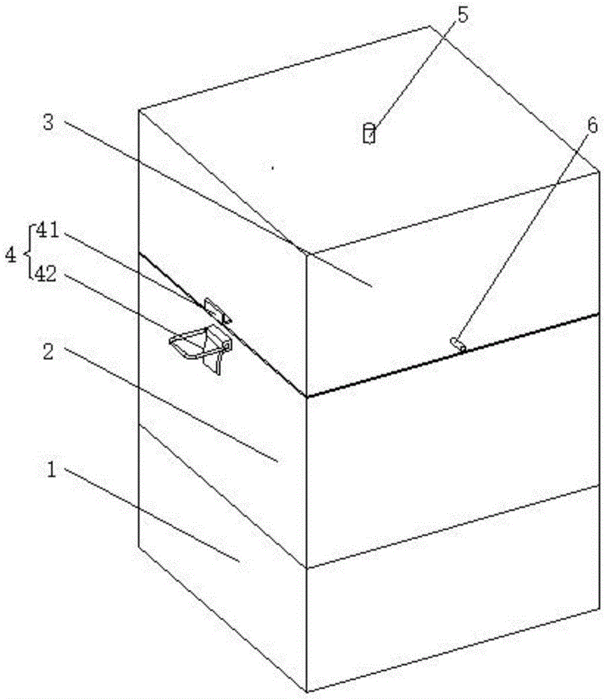
图1为本实用新型结构示意图;Fig. 1 is the structural representation of the utility model;
图2为本实用新型结构剖视示意图;Fig. 2 is the structural sectional schematic diagram of the present utility model;
图3为本实用新型结构上模具仰视示意图;Fig. 3 is the bottom view schematic diagram of the mold on the structure of the utility model;
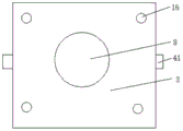
图4为本实用新型结构下模具俯视示意图;4 is a schematic top view of a mold under the structure of the utility model;
图5为本实用新型A处结构放大示意图。FIG. 5 is an enlarged schematic view of the structure at A of the present invention.
图中:1基座、2下模具、3上模具、4固定结构、41挂钩、42挂扣、5出水管、6进水管、7冷却腔、8模腔、9模芯、10环形切块、11液压柱、12凹槽、13油管、14加热网、15注胶管、16定位柱、17定位槽、18法兰盘。In the picture: 1 base, 2 lower mold, 3 upper mold, 4 fixed structure, 41 hook, 42 hook, 5 water outlet, 6 water inlet, 7 cooling cavity, 8 mold cavity, 9 mold core, 10 ring cut , 11 hydraulic columns, 12 grooves, 13 oil pipes, 14 heating nets, 15 rubber injection pipes, 16 positioning columns, 17 positioning grooves, 18 flanges.
具体实施方式Detailed ways
下面将结合本实用新型实施例中的附图,对本实用新型实施例中的技术方案进行清楚、完整地描述,显然,所描述的实施例仅仅是本实用新型一部分实施例,而不是全部的实施例。基于本实用新型中的实施例,本领域普通技术人员在没有做出创造性劳动前提下所获得的所有其他实施例,都属于本实用新型保护的范围。The technical solutions in the embodiments of the present utility model will be clearly and completely described below with reference to the accompanying drawings in the embodiments of the present utility model. Obviously, the described embodiments are only a part of the embodiments of the present utility model, rather than all the implementations. example. Based on the embodiments of the present invention, all other embodiments obtained by those of ordinary skill in the art without creative work fall within the protection scope of the present invention.
请参阅图1-5,本实用新型提供一种技术方案:一种模内切环瓶盖模具,包括基座1、下模具2和上模具3;基座1:基座1的上表面开设有凹槽12,凹槽12的内部底端设有液压柱11,基座1的上表面设有下模具2,下模具2的内部设有模芯9,模芯9的侧面套接有环形切块10,且环形切块10与下模具2滑动连接,模芯9的底侧与液压柱11的顶端连接,液压柱11伸出推动模芯9和环形切块10向上移动,进而使环形切块10对注胶管15的一端进行堵塞,进行对瓶盖模具进行模内切,便于使用者的使用;液压柱11的进液口上设有油管13,油管13贯穿基座1的外侧,油管13远离液压柱11的一端设有法兰盘18,油管13通过法兰盘18与外部高压油泵的输出口进行连接,便于对液压柱11的伸缩,上模具3:上模具3的内部设有注胶管15和加热网14,加热网14包裹在注胶管15的侧面,上模具3的底侧开设有模腔8,位于模腔8侧面在上模具3的内部设有冷却腔7,加热网14可以对注胶管15进行加热,防止注胶管15内部的熔融液进行加热,防止产品冷却成型的过程中注塑管道内部熔融液发生凝固,避免注塑管道发生堵塞,不影响再次使用,冷却腔7可以加快模腔8内部进行凝固,减少时间的浪费,提高工作效率;冷却腔7的侧面设有进水管6,冷却腔7的顶端设有出水管5,可以对冷却腔7内部的冷却液进行更换,加快产品成型,下模具2的上表面阵列分布有四个定位槽17,上模具3的底侧阵列分布有四个定位柱16,定位柱16与定位槽17对应套接,可以对下模具2和上模具3进行定位,进而使模芯9与模腔8位置进行定位,其中,上模具3通过定位柱16和定位槽17对下模具2进行连接,模腔8与模芯9对应套接,还包括固定结构4,固定结构4包括挂钩41和挂扣42,下模具2的侧面对称设有两个挂扣42,上模具3的侧面对称设有两个挂钩41,两个挂扣42分别与两个挂钩41挂接,可以使下模具2和上模具3进行固定,防止发生脱离。Please refer to Figures 1-5, the present utility model provides a technical solution: an in-mold ring bottle cap mold, comprising a
在使用时:液压柱11伸出推动模芯9和环形切块10向上移动,进而使环形切块10对注胶管15的一端进行堵塞,进行对瓶盖模具进行模内切,便于使用者的使用,同时,加热网14可以对注胶管15进行加热,防止注胶管15内部的熔融液进行加热,防止产品冷却成型的过程中注塑管道内部熔融液发生凝固,避免注塑管道发生堵塞,不影响再次使用,冷却腔7可以加快模腔8内部进行凝固,减少时间的浪费,提高工作效率。When in use: the
尽管已经示出和描述了本实用新型的实施例,对于本领域的普通技术人员而言,可以理解在不脱离本实用新型的原理和精神的情况下可以对这些实施例进行多种变化、修改、替换和变型,本实用新型的范围由所附权利要求及其等同物限定。Although the embodiments of the present invention have been shown and described, it will be understood by those skilled in the art that various changes and modifications can be made to these embodiments without departing from the principles and spirit of the present invention , alternatives and modifications, the scope of the present invention is defined by the appended claims and their equivalents.
Claims (5)
Priority Applications (1)
| Application Number | Priority Date | Filing Date | Title |
|---|---|---|---|
| CN201922091874.3U CN211105343U (en) | 2019-11-28 | 2019-11-28 | Mould inner cutting ring bottle cap mould |
Applications Claiming Priority (1)
| Application Number | Priority Date | Filing Date | Title |
|---|---|---|---|
| CN201922091874.3U CN211105343U (en) | 2019-11-28 | 2019-11-28 | Mould inner cutting ring bottle cap mould |
Publications (1)
| Publication Number | Publication Date |
|---|---|
| CN211105343U true CN211105343U (en) | 2020-07-28 |
Family
ID=71720604
Family Applications (1)
| Application Number | Title | Priority Date | Filing Date |
|---|---|---|---|
| CN201922091874.3U Expired - Fee Related CN211105343U (en) | 2019-11-28 | 2019-11-28 | Mould inner cutting ring bottle cap mould |
Country Status (1)
| Country | Link |
|---|---|
| CN (1) | CN211105343U (en) |
Cited By (1)
| Publication number | Priority date | Publication date | Assignee | Title |
|---|---|---|---|---|
| CN116175896A (en) * | 2023-04-21 | 2023-05-30 | 西安哗卫电子科技有限责任公司 | Stamping injection mold for manufacturing injection molding piece |
-
2019
- 2019-11-28 CN CN201922091874.3U patent/CN211105343U/en not_active Expired - Fee Related
Cited By (1)
| Publication number | Priority date | Publication date | Assignee | Title |
|---|---|---|---|---|
| CN116175896A (en) * | 2023-04-21 | 2023-05-30 | 西安哗卫电子科技有限责任公司 | Stamping injection mold for manufacturing injection molding piece |
Similar Documents
| Publication | Publication Date | Title |
|---|---|---|
| CN212736885U (en) | Injection mold | |
| CN207696941U (en) | Injection mold with cooling pipe | |
| CN105537568A (en) | Novel casting die cooling device | |
| CN206983170U (en) | A kind of injection mold with refrigerating function | |
| CN108943617A (en) | A kind of injection mold with refrigerating function | |
| CN111496219B (en) | A burr-free die-casting die for aluminum workpiece and its process | |
| CN220943140U (en) | Junction box cover die-casting forming die capable of rapidly cooling | |
| CN211542157U (en) | Machining die for TUP mobile phone protective sleeve | |
| CN221890840U (en) | Aluminum rod casting device | |
| CN219378932U (en) | Casting die fast in cooling speed | |
| CN207682827U (en) | A mold for the back shell of a television | |
| CN216230534U (en) | An injection mold for radar cover limit button | |
| CN216804162U (en) | Casting mold for pressing ring | |
| CN209454069U (en) | An injection mold with cooling function | |
| CN208006162U (en) | A kind of cured injection mold of anti-material | |
| CN211441028U (en) | An injection mold for cooling injection materials | |
| CN108162340A (en) | A kind of injection mold with ejecting mechanism | |
| CN220295804U (en) | Oil pan casting mould | |
| CN207465776U (en) | A kind of coat hanger die convenient for ejection moulding | |
| CN221736965U (en) | Exhaust structure of plastic mold | |
| CN220534810U (en) | Lens injection mold and injection condensing device | |
| CN219968669U (en) | Bottle lid mechanism of moulding plastics with cooling function | |
| CN221677953U (en) | Water cooling mechanism for injection mold | |
| CN222309733U (en) | Injection molding device for plastic shell of stationery | |
| CN221913106U (en) | Self-demolding injection mold |
Legal Events
| Date | Code | Title | Description |
|---|---|---|---|
| GR01 | Patent grant | ||
| GR01 | Patent grant | ||
| CF01 | Termination of patent right due to non-payment of annual fee |
Granted publication date: 20200728 |
|
| CF01 | Termination of patent right due to non-payment of annual fee |