CN211104459U - High-speed circular sawing machine actuating mechanism - Google Patents
High-speed circular sawing machine actuating mechanism Download PDFInfo
- Publication number
- CN211104459U CN211104459U CN201920732883.3U CN201920732883U CN211104459U CN 211104459 U CN211104459 U CN 211104459U CN 201920732883 U CN201920732883 U CN 201920732883U CN 211104459 U CN211104459 U CN 211104459U
- Authority
- CN
- China
- Prior art keywords
- base
- fixedly connected
- roller
- splint
- speed circular
- Prior art date
- Legal status (The legal status is an assumption and is not a legal conclusion. Google has not performed a legal analysis and makes no representation as to the accuracy of the status listed.)
- Expired - Fee Related
Links
Images

Abstract
The utility model discloses a high-speed circular sawing machine actuating mechanism, the on-line screen storage device comprises a base, the top of base is equipped with the spout, the inside sliding connection of spout has the flat board, dull and stereotyped top fixedly connected with motor, fixedly connected with saw bit on the output shaft of motor, the other end fixed connection of pivot is on servo motor's output shaft, the opposite side fixedly connected with second pneumatic cylinder of base, the first splint of top fixedly connected with of second pneumatic cylinder, the fixedly connected with and the first splint assorted second splint of base. The utility model discloses place the material between second roller and third roller, drive the third roller through the lead screw and press from both sides the material tightly, drive second roller and third roller by servo motor and rotate, export the top of base with the material, then saw cut the material through first pneumatic cylinder promotion saw bit, changed traditional mode that needs artifical pay-off, improved work efficiency.
Description
Technical Field
The utility model relates to a sawing machine technical field specifically is a high-speed circular sawing machine actuating mechanism.
Background
The sawing machine uses a saw as a cutter, and cuts the cut wood through the reciprocating motion of a band saw or the rotating motion of a circular saw. Common sawing machines are band sawing machines and circular sawing machines. Circular sawing machines can be classified into metal circular sawing machines and woodworking circular sawing machines according to the processing products. The feeding mode is divided into a vertical type, a horizontal type and a scissor type. The control mode can be divided into manual, semi-automatic and full-automatic. And a special material rack is arranged according to the requirement.
Present saw cutter needs the manual work to place the material on saw cutter, then presss from both sides the material tightly, needs the manual work to take off the material after saw cutting, after the material is saw cut, the incision can produce the burr, and the temperature can increase, when the manual work is taken, causes the potential safety hazard easily, and work efficiency is lower. To this end, we propose a high-speed circular saw drive mechanism.
SUMMERY OF THE UTILITY MODEL
An object of the utility model is to provide a high-speed circular sawing machine actuating mechanism places the material between second roller and third roller, drives the third roller through the lead screw and presss from both sides the material tightly, drives second roller and third roller by servo motor and rotates, exports the top of base with the material, then promotes the saw bit through first pneumatic cylinder and saw cuts the material to solve the problem that proposes among the above-mentioned background art.
In order to achieve the above object, the utility model provides a following technical scheme: a high-speed circular sawing machine driving mechanism comprises a base, wherein a sliding groove is formed in the top of the base, a flat plate is connected to the inside of the sliding groove in a sliding mode, a motor is fixedly connected to the top of the flat plate, a saw blade is fixedly connected to an output shaft of the motor, a first hydraulic cylinder is fixedly connected to one side of the flat plate, the first hydraulic cylinder is fixedly connected to one side of the base, a first roller shaft and a second roller shaft are respectively sleeved on two sides of the top of the base through bearings, a first belt pulley is fixedly connected to one end of the first roller shaft, a second belt pulley is connected to the first belt pulley through belt transmission, the second belt pulley is fixedly connected to the outer side of a rotating shaft, one end of the rotating shaft is fixedly connected to one end of the second roller shaft, the other end of the rotating shaft is fixedly connected to an output shaft, and adjusting device is located the top of second roller, the opposite side fixedly connected with second pneumatic cylinder of base, the first splint of top fixedly connected with of second pneumatic cylinder, the fixedly connected with and the first splint assorted second splint of base.
Preferably, adjusting device includes U type frame, the top of U type frame is connected with the lead screw through the bearing, the lower extreme threaded connection of lead screw has the dead lever, the one end of dead lever is passed through the bearing and is connected in the one end of third roller.
Preferably, the bottom of the base is provided with four groups of supporting legs, and the four groups of supporting legs are uniformly distributed at the bottom of the base.
Preferably, the first roller shafts are provided with four groups at least, and the four groups of first roller shafts are arranged tangentially.
Preferably, the top of the base is provided with a groove, and the groove penetrates through one side of the base.
Preferably, the servo motor is fixedly connected to the top of the fixing plate, and the fixing plate is fixedly connected to one side of the base.
Compared with the prior art, the beneficial effects of the utility model are that:
1. the utility model discloses place the material between second roller and third roller, drive the third roller through the lead screw and press from both sides the material tightly, drive second roller and third roller rotation by servo motor, export the material to the top of base, then promote the saw bit through first pneumatic cylinder and saw cut the material, changed traditional mode that needs artifical pay-off, improved work efficiency;
2. the utility model discloses servo motor drives first roller through the belt and rotates in the pivoted, can carry out the material after saw cutting, has changed the artifical mode of taking the material of traditional needs, has improved safety, and the second pneumatic cylinder drives first splint and can press from both sides the material tightly, and the effectual assurance when saw cutting, the material can not remove.
Drawings
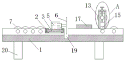
Fig. 1 is a schematic structural view of the present invention;
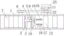
fig. 2 is a top view of the present invention;
fig. 3 is an enlarged schematic view of area a in fig. 1.
In the figure: the automatic cutting machine comprises a base 1, a sliding groove 2, a flat plate 3, a first hydraulic cylinder 4, a motor 5, a saw blade 6, a first roller shaft 7, a first belt pulley 8, a belt 9, a second belt pulley 10, a servo motor 11, a third roller shaft 12, a U-shaped frame 13, a lead screw 14, a second roller shaft 15, a second hydraulic cylinder 16, a first clamping plate 17, a second clamping plate 18, a groove 19, a supporting leg 20, a bearing 21, a rotating shaft 22, an adjusting device 23, a fixing rod 24 and a fixing plate 25.
Detailed Description
The technical solutions in the embodiments of the present invention will be described clearly and completely with reference to the accompanying drawings in the embodiments of the present invention, and it is obvious that the described embodiments are only some embodiments of the present invention, not all embodiments. Based on the embodiments in the present invention, all other embodiments obtained by a person skilled in the art without creative work belong to the protection scope of the present invention.
Referring to fig. 1 to 3, the present invention provides a technical solution: a high-speed circular sawing machine actuating mechanism comprises a base 1, wherein a chute 2 is arranged at the top of the base 1, a flat plate 3 is connected to the inside of the chute 2 in a sliding manner, a motor 5 is fixedly connected to the top of the flat plate 3, a saw blade 6 is fixedly connected to the output shaft of the motor 5, a first hydraulic cylinder 4 is fixedly connected to one side of the flat plate 3, the first hydraulic cylinder 4 is fixedly connected to one side of the base 1, a first roller shaft 7 and a second roller shaft 15 are respectively sleeved on two sides of the top of the base 1 through a bearing 21, a first belt pulley 8 is fixedly connected to one end of the first roller shaft 7, a second belt pulley 10 is connected to the first belt pulley 8 through a belt 9 in a transmission manner, the second belt pulley 10 is fixedly connected to the outer side of a rotating shaft 22, one end of the rotating shaft 22 is fixedly connected to one end of the second roller shaft 15, and the other, the top both sides of base 1 all are equipped with adjusting device 23, and adjusting device 23 is located the top of second roller 15, the opposite side fixedly connected with second pneumatic cylinder 16 of base 1, the first splint 17 of top fixedly connected with of second pneumatic cylinder 16, the fixedly connected with of base 1 and first splint 17 assorted second splint 18.
Specifically, adjusting device 23 includes U type frame 13, the top of U type frame 13 is connected with lead screw 14 through bearing 21, the lower extreme threaded connection of lead screw 14 has dead lever 24, bearing 21 is passed through to the one end of dead lever 24 and is connected in the one end of third roller 12, when sawing not equidimension material, adjusts third roller 12 through lead screw 14 and presss from both sides the material tightly, and the servo motor 11 of being convenient for carries the material.
Specifically, four groups of supporting legs 20 are arranged at the bottom of the base 1, and the four groups of supporting legs 20 are uniformly distributed at the bottom of the base 1, so that the four groups of supporting legs 20 are beneficial to improving the overall stability.
Specifically, first roller 7 is provided with four groups at least, and four groups of first roller 7 are tangent setting, and this first roller 7 is favorable to carrying the material after the saw cutting out the top of base 1.
Specifically, the top of base 1 is equipped with recess 19, and recess 19 runs through in one side of base 1, and this recess 19 rotates for saw bit 6 and provides the space, also is favorable to collecting the disintegrating slag of material.
Specifically, servo motor 11 fixed connection is in the top of fixed plate 25, and fixed plate 25 fixed connection is in one side of base 1, and this fixed plate 25 is favorable to improving servo motor 11 during operation's stability.
The working principle is as follows: when the material taking device is used, materials are placed between the second roller shaft 15 and the third roller shaft 12, the third roller shaft 12 is adjusted through the screw rod 14 to clamp the materials, the servo motor 11 is convenient to convey the materials, the servo motor 11 drives the second roller shaft 15 and the third roller shaft 12 to rotate, the materials are output to the top of the base 1, then the second hydraulic cylinder 16 drives the first clamping plate 17 to clamp the materials, the materials are effectively guaranteed not to move when being cut, then the first hydraulic cylinder 2 is opened to push the flat plate 3 to move in the sliding groove 2, the motor 5 drives the saw blade 6 to cut the materials, the traditional mode of needing manual feeding is changed, the working efficiency is improved, the servo motor 11 drives the first roller shaft 7 to rotate through the belt 9 when rotating, the cut materials can be conveyed out of the top of the base, and the traditional mode of needing manual material taking is changed, the safety is improved.
Although embodiments of the present invention have been shown and described, it will be appreciated by those skilled in the art that changes, modifications, substitutions and alterations can be made in these embodiments without departing from the principles and spirit of the invention, the scope of which is defined in the appended claims and their equivalents.
Claims (6)
1. The utility model provides a high-speed circular sawing machine actuating mechanism, includes base (1), its characterized in that: the top of the base (1) is provided with a sliding groove (2), the inside of the sliding groove (2) is connected with a flat plate (3) in a sliding manner, the top of the flat plate (3) is fixedly connected with a motor (5), an output shaft of the motor (5) is fixedly connected with a saw blade (6), one side of the flat plate (3) is fixedly connected with a first hydraulic cylinder (4), the first hydraulic cylinder (4) is fixedly connected with one side of the base (1), two sides of the top of the base (1) are respectively sleeved with a first roller shaft (7) and a second roller shaft (15) through bearings (21), one end of the first roller shaft (7) is fixedly connected with a first belt pulley (8), the first belt pulley (8) is connected with a second belt pulley (10) through a belt (9) in a transmission manner, the second belt pulley (10) is fixedly connected with the outer side of a rotating shaft (22), one end of the rotating shaft (22) is fixedly connected with one end, the other end fixed connection of pivot (22) is on the output shaft of servo motor (11), the top both sides of base (1) all are equipped with adjusting device (23), and adjusting device (23) are located the top of second roller (15), opposite side fixedly connected with second pneumatic cylinder (16) of base (1), the first splint (17) of top fixedly connected with of second pneumatic cylinder (16), the fixedly connected with and the first splint (17) assorted second splint (18) of base (1).
2. The high-speed circular saw machine driving mechanism as claimed in claim 1, wherein: adjusting device (23) are including U type frame (13), the top of U type frame (13) is connected with lead screw (14) through bearing (21), the lower extreme threaded connection of lead screw (14) has dead lever (24), the one end of dead lever (24) is passed through bearing (21) and is connected in the one end of third roller (12).
3. The high-speed circular saw machine driving mechanism as claimed in claim 1, wherein: the bottom of base (1) is equipped with four groups of landing legs (20), and four groups of landing legs (20) evenly distributed in the bottom of base (1).
4. The high-speed circular saw machine driving mechanism as claimed in claim 1, wherein: the first roller shafts (7) are at least provided with four groups, and the four groups of first roller shafts (7) are arranged tangentially.
5. The high-speed circular saw machine driving mechanism as claimed in claim 1, wherein: the top of the base (1) is provided with a groove (19), and the groove (19) penetrates through one side of the base (1).
6. The high-speed circular saw machine driving mechanism as claimed in claim 1, wherein: the servo motor (11) is fixedly connected to the top of the fixing plate (25), and the fixing plate (25) is fixedly connected to one side of the base (1).
Priority Applications (1)
| Application Number | Priority Date | Filing Date | Title |
|---|---|---|---|
| CN201920732883.3U CN211104459U (en) | 2019-05-21 | 2019-05-21 | High-speed circular sawing machine actuating mechanism |
Applications Claiming Priority (1)
| Application Number | Priority Date | Filing Date | Title |
|---|---|---|---|
| CN201920732883.3U CN211104459U (en) | 2019-05-21 | 2019-05-21 | High-speed circular sawing machine actuating mechanism |
Publications (1)
| Publication Number | Publication Date |
|---|---|
| CN211104459U true CN211104459U (en) | 2020-07-28 |
Family
ID=71693176
Family Applications (1)
| Application Number | Title | Priority Date | Filing Date |
|---|---|---|---|
| CN201920732883.3U Expired - Fee Related CN211104459U (en) | 2019-05-21 | 2019-05-21 | High-speed circular sawing machine actuating mechanism |
Country Status (1)
| Country | Link |
|---|---|
| CN (1) | CN211104459U (en) |
Cited By (1)
| Publication number | Priority date | Publication date | Assignee | Title |
|---|---|---|---|---|
| CN112720719A (en) * | 2020-12-15 | 2021-04-30 | 郑家俊 | A equipment for stake cutting |
-
2019
- 2019-05-21 CN CN201920732883.3U patent/CN211104459U/en not_active Expired - Fee Related
Cited By (1)
| Publication number | Priority date | Publication date | Assignee | Title |
|---|---|---|---|---|
| CN112720719A (en) * | 2020-12-15 | 2021-04-30 | 郑家俊 | A equipment for stake cutting |
Similar Documents
| Publication | Publication Date | Title |
|---|---|---|
| CN213005736U (en) | Be applicable to building timber cutting process equipment | |
| CN205201709U (en) | Slab multi -disc saw | |
| CN211104459U (en) | High-speed circular sawing machine actuating mechanism | |
| CN207402906U (en) | A kind of numerical control multiple-piece wood sawing machine | |
| CN207103946U (en) | A kind of metal plate cutting device | |
| CN205075091U (en) | Filling machine is chopped in succession to double knives | |
| CN215943824U (en) | Die-cutting machine for carton packaging production | |
| CN210436314U (en) | Device for forming comb teeth at end part of finger joint material | |
| CN212602331U (en) | Solid wood cutting equipment | |
| CN213732238U (en) | Automatic wood cutting machine | |
| CN205816939U (en) | A kind of translatable cutter sweep | |
| CN214561600U (en) | Automatic die cutting machine based on door plant production usefulness | |
| CN2902628Y (en) | Feed cutting device of carpenter's material breaking saw | |
| CN212919648U (en) | Paper products production is with cutting equipment who has sweeps and collect structure | |
| CN210757912U (en) | Guillootine convenient to fixed raw materials | |
| CN210139470U (en) | Sawing machine unloading mechanism | |
| CN2582830Y (en) | Lumber band saw automatic slicer | |
| CN107159966A (en) | Tubular workpiece groover and its processing technology | |
| CN217573097U (en) | Automatic slicer limit structure | |
| CN207824085U (en) | A kind of cutter with double saw bits | |
| CN207130522U (en) | A kind of strip cutting-off machine structure | |
| CN205704579U (en) | Automatically milling type machine | |
| CN219727345U (en) | Carton deckle edge cutting device | |
| CN219632715U (en) | Cutting machine | |
| CN110712244B (en) | Woodworking band saw capable of adjusting cutting direction |
Legal Events
| Date | Code | Title | Description |
|---|---|---|---|
| GR01 | Patent grant | ||
| GR01 | Patent grant | ||
| CF01 | Termination of patent right due to non-payment of annual fee | ||
| CF01 | Termination of patent right due to non-payment of annual fee |
Granted publication date: 20200728 |