CN211088906U - A network security based distribution box - Google Patents
A network security based distribution box Download PDFInfo
- Publication number
- CN211088906U CN211088906U CN201922375869.5U CN201922375869U CN211088906U CN 211088906 U CN211088906 U CN 211088906U CN 201922375869 U CN201922375869 U CN 201922375869U CN 211088906 U CN211088906 U CN 211088906U
- Authority
- CN
- China
- Prior art keywords
- fixedly connected
- box
- water tank
- network security
- fan
- Prior art date
- Legal status (The legal status is an assumption and is not a legal conclusion. Google has not performed a legal analysis and makes no representation as to the accuracy of the status listed.)
- Expired - Fee Related
Links
Images


Landscapes
- Patch Boards (AREA)
Abstract
本实用新型公开了一种基于网络安全的配电箱,包括箱体,所述箱体的底部固定连接有通风管,且通风管的内壁固定连接有圆锥形滤网,所述箱体的侧面固定连接有设备箱,所述设备箱的内壁固定连接有隔板,所述隔板的上表面固定连接有垫板,所述垫板的表面固定连接有风机。该基于网络安全的配电箱,通过设置箱体、设备箱、风机、引风机、空心软管、水箱和通风管,便于风机搅动设备箱内的气体,并使引风机通过连接管吸引风力,使风力通过空心软管进入到水箱中中,经过水中滤网层过滤,灰尘颗粒遇水下沉,干净冷却的气体通过通风管进入到箱体内部进行对电器进行降温冷却,从而达到该基于网络安全的配电箱具有除尘降温的效果。
The utility model discloses a power distribution box based on network security, which comprises a box body, a ventilation pipe is fixedly connected to the bottom of the box body, and a conical filter screen is fixedly connected to the inner wall of the ventilation pipe. An equipment box is fixedly connected, a partition is fixedly connected to the inner wall of the equipment box, a backing plate is fixedly connected to the upper surface of the partition, and a fan is fixedly connected to the surface of the backing plate. The network security-based distribution box, by setting the box, equipment box, fan, induced draft fan, hollow hose, water tank and ventilation pipe, is convenient for the fan to stir the gas in the equipment box, and the induced draft fan can attract wind through the connecting pipe, The wind enters the water tank through a hollow hose, and is filtered by the water filter layer, the dust particles sink in the water, and the clean and cooled gas enters the inside of the box through the ventilation pipe to cool down the electrical appliances, so as to achieve this network-based system. The safe distribution box has the effect of dust removal and cooling.
Description
技术领域technical field
本实用新型涉及配电箱技术领域,具体为一种基于网络安全的配电箱。The utility model relates to the technical field of distribution boxes, in particular to a distribution box based on network security.
背景技术Background technique
网络安全是指网络系统的硬件、软件及其系统中的数据受到保护,不因偶然的或者恶意的原因而遭受到破坏、更改、泄露,系统连续可靠正常地运行,网络服务不中断。配电箱能够为网络安全硬件提供稳定的电力,在网络硬件运行时起到重要作用,然而配电箱工作时,配电箱能够利用内置风机和外界进行热交换。Network security means that the hardware, software and data in the network system are protected from being damaged, altered or leaked due to accidental or malicious reasons, the system operates continuously, reliably and normally, and network services are not interrupted. The power distribution box can provide stable power for the network security hardware and play an important role in the operation of the network hardware. However, when the power distribution box is working, the power distribution box can use the built-in fan to exchange heat with the outside world.
目前的配电箱与外界进行热交换的过程中,外界的空气将进入配电箱,进而,空气中的灰尘也将进入配电箱;若长时间不清理配电箱,将导致配电箱内积压大量的灰尘,影响配电箱的散热,甚至导致配电箱发生损坏,对生产、生活造成不必要的影响。In the process of heat exchange between the current distribution box and the outside world, the outside air will enter the distribution box, and then the dust in the air will also enter the distribution box; if the distribution box is not cleaned for a long time, the distribution box will be damaged. A large amount of dust is accumulated inside, which affects the heat dissipation of the distribution box, and even causes damage to the distribution box, which has an unnecessary impact on production and life.
实用新型内容Utility model content
本实用新型的目的在于提供一种基于网络安全的配电箱,以解决上述背景技术中提出的问题。The purpose of the present invention is to provide a power distribution box based on network security to solve the problems raised in the above background technology.
为实现上述目的,本实用新型提供如下技术方案:一种基于网络安全的配电箱,包括箱体,所述箱体的底部固定连接有通风管,且通风管的内壁固定连接有圆锥形滤网,所述箱体的侧面固定连接有设备箱,所述设备箱的内壁固定连接有隔板,所述隔板的上表面固定连接有垫板,所述垫板的表面固定连接有风机,所述隔板的上表面贯穿固定连接有连接管,所述连接管的出气端固定连接有引风机,所述引风机的出气端固定连接有空心软管,所述空心软管的表面开设有出气孔,所述箱体的底部固定连接有水箱,所述水箱的内壁固定连接有滤网层,所述水箱的侧面固定连接有单向阀门,所述水箱的内底壁中心处开设有漏斗孔,且漏斗孔的内壁螺纹连接有固定水塞,所述水箱的底部固定连接有支撑板,所述支撑板的下表面固定连接有支撑柱,所述支撑板的下表面开设有圆槽。In order to achieve the above purpose, the present utility model provides the following technical solutions: a network security-based distribution box, comprising a box body, the bottom of the box body is fixedly connected with a ventilation pipe, and the inner wall of the ventilation pipe is fixedly connected with a conical filter. The side of the box body is fixedly connected with an equipment box, the inner wall of the equipment box is fixedly connected with a partition plate, the upper surface of the partition plate is fixedly connected with a backing plate, and the surface of the backing plate is fixedly connected with a fan, The upper surface of the partition is fixedly connected with a connecting pipe, the air outlet end of the connecting pipe is fixedly connected with an induced draft fan, and the air outlet end of the induced draft fan is fixedly connected with a hollow hose, and the surface of the hollow hose is provided with Air outlet, a water tank is fixedly connected to the bottom of the box body, a filter screen layer is fixedly connected to the inner wall of the water tank, a one-way valve is fixedly connected to the side of the water tank, and a funnel is opened at the center of the inner bottom wall of the water tank The inner wall of the funnel hole is screwed with a fixed water plug, the bottom of the water tank is fixedly connected with a support plate, the lower surface of the support plate is fixedly connected with a support column, and the lower surface of the support plate is provided with a circular groove.
优选的,所述通风管的底端贯穿箱体的内底壁并延伸至水箱的内顶壁,且通风管的内壁固定连接有两层圆锥形滤网。Preferably, the bottom end of the ventilation pipe penetrates through the inner bottom wall of the box body and extends to the inner top wall of the water tank, and the inner wall of the ventilation pipe is fixedly connected with two layers of conical filter screens.
优选的,所述设备箱的侧面开设与设备箱内风机相贯通的圆孔,且圆孔的内壁设置有隔灰滤网。Preferably, the side of the equipment box is provided with a circular hole that communicates with the fan in the equipment box, and the inner wall of the circular hole is provided with an ash-separating filter screen.
优选的,所述设备箱通过隔板分成上下空腔,且引风机位于下空腔中,所述引风机设置的高度比水箱的上表面高十公分。Preferably, the equipment box is divided into upper and lower cavities by partitions, and the induced draft fan is located in the lower cavity, and the height of the induced draft fan is set ten centimeters higher than the upper surface of the water tank.
优选的,所述空心软管位于滤网层的下方,且水箱的内壁设置有两层滤网层。Preferably, the hollow hose is located below the filter screen layer, and the inner wall of the water tank is provided with two layers of filter screen layers.
优选的,所述支撑板下表面开设的圆槽为漏斗形,且圆槽开设的大小与水箱底部的固定水塞相适配。Preferably, the circular groove opened on the lower surface of the support plate is funnel-shaped, and the size of the circular groove is adapted to the fixed water plug at the bottom of the water tank.
有益效果beneficial effect
本实用新型提供了一种基于网络安全的配电箱,该基于网络安全的配电箱,通过设置箱体、设备箱、风机、引风机、空心软管、水箱和通风管,便于风机搅动设备箱内的气体,并使引风机通过连接管吸引风力,通过空心软管表面上的出气孔进入到水箱中的液体中,经过水中滤网层过滤,灰尘颗粒遇水下沉,干净冷却的气体通过通风管进入到箱体内部进行对电器进行降温冷却,且不使用风力冷却时,通风管内的圆锥形滤网,便于过滤水蒸气或空气杂质,从而达到该基于网络安全的配电箱具有除尘降温的效果。The utility model provides a distribution box based on network security. The distribution box based on network security is provided with a box body, an equipment box, a fan, an induced draft fan, a hollow hose, a water tank and a ventilation pipe, which is convenient for the fan to stir equipment. The gas in the box, and the induced draft fan attracts the wind through the connecting pipe, enters the liquid in the water tank through the air outlet on the surface of the hollow hose, and is filtered by the water filter layer, the dust particles sink in the water, and the clean cooling gas The ventilation pipe enters the inside of the box to cool down the electrical appliance. When wind cooling is not used, the conical filter in the ventilation pipe is convenient for filtering water vapor or air impurities, so as to achieve the network security-based distribution box with dust removal. cooling effect.
附图说明Description of drawings
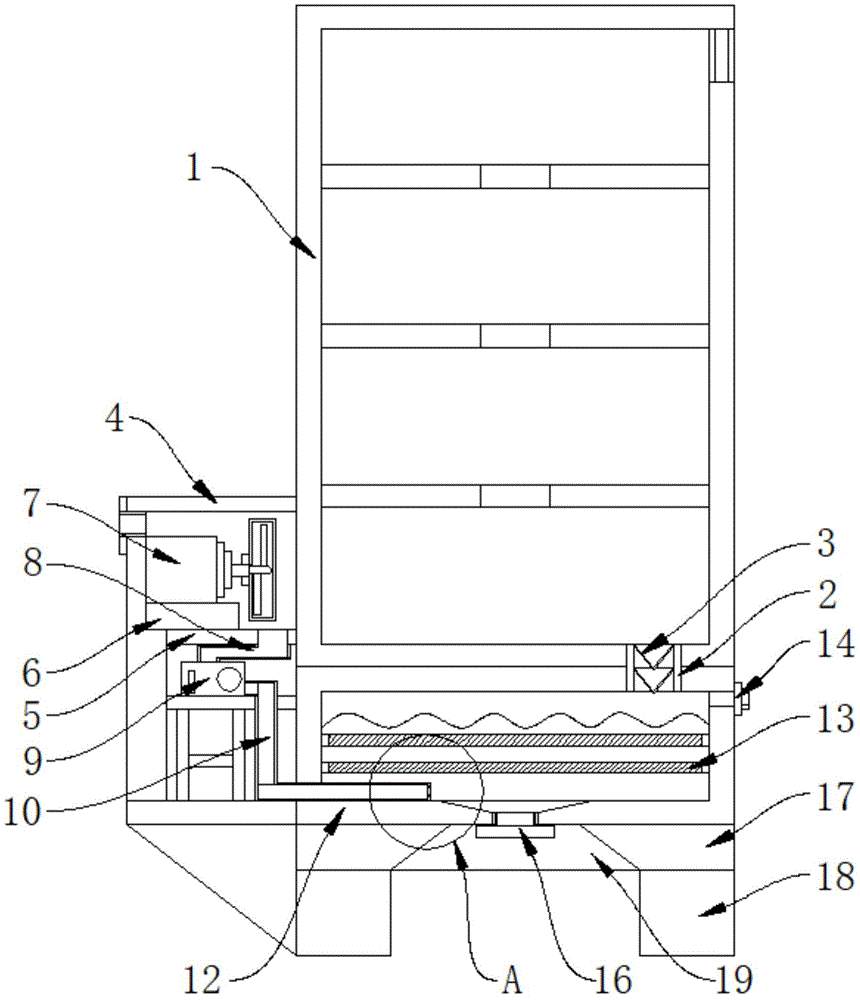
图1为本实用新型结构正剖示意图;Fig. 1 is the front sectional schematic diagram of the structure of the utility model;
图2为本实用新型结构正视示意图;Fig. 2 is the front view schematic diagram of the structure of the utility model;
图3为本实用新型结构图1中A的放大示意图。FIG. 3 is an enlarged schematic view of A in FIG. 1 of the structure of the present invention.
图中:1箱体、2通风管、3圆锥形滤网、4设备箱、5隔板、6垫板、7风机、8连接管、9引风机、10空心软管、11出气孔、12水箱、13滤网层、14单向阀门、15漏斗孔、16固定水塞、17支撑板、18支撑柱、19圆槽。In the picture: 1 box, 2 ventilation pipes, 3 conical filters, 4 equipment boxes, 5 partitions, 6 backing plates, 7 fans, 8 connecting pipes, 9 induced draft fans, 10 hollow hoses, 11 air vents, 12 Water tank, 13 screen layers, 14 one-way valve, 15 funnel hole, 16 fixed water plug, 17 support plate, 18 support column, 19 round groove.
具体实施方式Detailed ways
下面将结合本实用新型实施例中的附图,对本实用新型实施例中的技术方案进行清楚、完整地描述,显然,所描述的实施例仅仅是本实用新型一部分实施例,而不是全部的实施例。基于本实用新型中的实施例,本领域普通技术人员在没有做出创造性劳动前提下所获得的所有其他实施例,都属于本实用新型保护的范围。The technical solutions in the embodiments of the present utility model will be clearly and completely described below with reference to the accompanying drawings in the embodiments of the present utility model. Obviously, the described embodiments are only a part of the embodiments of the present utility model, rather than all the implementations. example. Based on the embodiments of the present invention, all other embodiments obtained by those of ordinary skill in the art without creative work fall within the protection scope of the present invention.
请参阅图1-3,本实用新型提供一种技术方案:一种基于网络安全的配电箱,包括箱体1,箱体1的侧面顶部开设有出风孔,箱体1的底部固定连接有通风管2,且通风管2的内壁固定连接有圆锥形滤网3,箱体1的侧面固定连接有设备箱4,设备箱4的内壁固定连接有隔板5,隔板5的上表面固定连接有垫板6,垫板6的表面固定连接有风机7,设备箱4的侧面开设与设备箱4内风机7相贯通的圆孔,且圆孔的内壁设置有隔灰滤网,隔板5的上表面贯穿固定连接有连接管8,连接管8的出气端固定连接有引风机9,引风机9的出气端固定连接有空心软管10,空心软管10的表面开设有出气孔11。1-3, the present utility model provides a technical solution: a power distribution box based on network security, including a
箱体1的底部固定连接有水箱12,通风管2的底端贯穿箱体1的内底壁并延伸至水箱12的内顶壁,且通风管2的内壁固定连接有两层圆锥形滤网3,设备箱4通过隔板5分成上下空腔,且引风机9位于下空腔中,引风机9设置的高度比水箱12的上表面高十公分,且水箱12的正面嵌设有透明观察窗,便于观察水箱内部液体及沉淀物情况,及时处理,水箱12的内壁固定连接有滤网层13,空心软管10位于滤网层13的下方,且水箱12的内壁设置有两层滤网层13,水箱12的侧面固定连接有单向阀门14,水箱12的内底壁中心处开设有漏斗孔15,且漏斗孔15的内壁螺纹连接有固定水塞16,便于旋转固定水塞16,使水箱12内的水和杂质排出,水箱12的底部固定连接有支撑板17,支撑板17的下表面固定连接有支撑柱18,支撑板17的下表面开设有圆槽19,支撑板17下表面开设的圆槽19为漏斗形,且圆槽19开设的大小与水箱12底部的固定水塞16相适配。The bottom of the
工作原理:在使用基于网络安全的配电箱时,通过启动风机7,使其搅动设备箱4内的气体,并使引风机9通过连接管8吸引风力从空心软管10排出,通过空心软管10表面上的出气孔11进入到水箱12中的液体中,经过水中滤网层13过滤,灰尘颗粒遇水下沉,干净冷却的气体通过通风管2进入到箱体1内部进行对电器进行降温冷却,且不使用风力冷却时,通风管2内的圆锥形滤网3,便于过滤水蒸气或空气杂质,从而达到该基于网络安全的配电箱具有除尘降温的效果。Working principle: When using the distribution box based on network security, start the
尽管已经示出和描述了本实用新型的实施例,对于本领域的普通技术人员而言,可以理解在不脱离本实用新型的原理和精神的情况下可以对这些实施例进行多种变化、修改、替换和变型,本实用新型的范围由所附权利要求及其等同物限定。Although the embodiments of the present invention have been shown and described, it will be understood by those skilled in the art that various changes and modifications can be made to these embodiments without departing from the principles and spirit of the present invention , alternatives and modifications, the scope of the present invention is defined by the appended claims and their equivalents.
Claims (6)
Priority Applications (1)
| Application Number | Priority Date | Filing Date | Title |
|---|---|---|---|
| CN201922375869.5U CN211088906U (en) | 2019-12-26 | 2019-12-26 | A network security based distribution box |
Applications Claiming Priority (1)
| Application Number | Priority Date | Filing Date | Title |
|---|---|---|---|
| CN201922375869.5U CN211088906U (en) | 2019-12-26 | 2019-12-26 | A network security based distribution box |
Publications (1)
| Publication Number | Publication Date |
|---|---|
| CN211088906U true CN211088906U (en) | 2020-07-24 |
Family
ID=71631629
Family Applications (1)
| Application Number | Title | Priority Date | Filing Date |
|---|---|---|---|
| CN201922375869.5U Expired - Fee Related CN211088906U (en) | 2019-12-26 | 2019-12-26 | A network security based distribution box |
Country Status (1)
| Country | Link |
|---|---|
| CN (1) | CN211088906U (en) |
Cited By (1)
| Publication number | Priority date | Publication date | Assignee | Title |
|---|---|---|---|---|
| CN112071556A (en) * | 2020-09-18 | 2020-12-11 | 廖颖 | Power box type transformer |
-
2019
- 2019-12-26 CN CN201922375869.5U patent/CN211088906U/en not_active Expired - Fee Related
Cited By (1)
| Publication number | Priority date | Publication date | Assignee | Title |
|---|---|---|---|---|
| CN112071556A (en) * | 2020-09-18 | 2020-12-11 | 廖颖 | Power box type transformer |
Similar Documents
| Publication | Publication Date | Title |
|---|---|---|
| CN206717665U (en) | A kind of wet dust removal all-in-one | |
| WO2018077081A1 (en) | Dust removal device for use in ceramic production | |
| CN206419284U (en) | A kind of water pump filter | |
| CN207251016U (en) | A kind of heat radiating type outdoor electric cabinet based on rainwater-collecting | |
| CN108170235B (en) | A computer equipment equipped with an air filter mechanism | |
| TW201224374A (en) | Container data center and ventilating system thereof | |
| CN207221618U (en) | Polishing dust remover | |
| CN211159107U (en) | Environment-friendly dust removing equipment for mechanical automatic processing workshop | |
| CN205699922U (en) | Vacuum steel-making special oil membrane type dedusting cooler | |
| CN209307681U (en) | Laundry care appliance and its supply and discharge water installations | |
| CN205886458U (en) | Negative pressure formula air purification device | |
| CN211914743U (en) | Medical instrument circulation perfusion belt cleaning device | |
| CN206045615U (en) | A kind of energy-efficient mist of oil withdrawer | |
| CN207460646U (en) | A kind of electrical engineering electric box | |
| CN203215950U (en) | Filter screen of air conditioner fan coil water receiving box | |
| CN211183040U (en) | A control cabinet with good heat dissipation | |
| CN107401927A (en) | A kind of glassware waste heat recovery heat sink | |
| CN220965458U (en) | External heat dissipation device of water-cooled mainframe | |
| CN221815655U (en) | A dust collecting device | |
| CN220629871U (en) | A cabinet with a heat dissipation structure | |
| CN206739815U (en) | A kind of copper strips air-dry apparatus | |
| CN204892491U (en) | Aluminum plate surface impurity removal device | |
| CN222305273U (en) | Dust collecting equipment for fireproof door plate processing factory building | |
| CN204953436U (en) | Driftage brake disc dust cleaning device | |
| CN205717441U (en) | a range hood |
Legal Events
| Date | Code | Title | Description |
|---|---|---|---|
| GR01 | Patent grant | ||
| GR01 | Patent grant | ||
| CF01 | Termination of patent right due to non-payment of annual fee | ||
| CF01 | Termination of patent right due to non-payment of annual fee |
Granted publication date: 20200724 |