CN211079456U - Multi-strand twisting machine with adjustable tension - Google Patents
Multi-strand twisting machine with adjustable tension Download PDFInfo
- Publication number
- CN211079456U CN211079456U CN201921255452.9U CN201921255452U CN211079456U CN 211079456 U CN211079456 U CN 211079456U CN 201921255452 U CN201921255452 U CN 201921255452U CN 211079456 U CN211079456 U CN 211079456U
- Authority
- CN
- China
- Prior art keywords
- positioning
- turntable
- ring
- twisting machine
- seat
- Prior art date
- Legal status (The legal status is an assumption and is not a legal conclusion. Google has not performed a legal analysis and makes no representation as to the accuracy of the status listed.)
- Expired - Fee Related
Links
Images


Landscapes
- Yarns And Mechanical Finishing Of Yarns Or Ropes (AREA)
Abstract
本实用新型涉及一种张力可调节多股捻线机。为了解决现有技术中捻线机张力器成本高、容易打滑,绕线筒容易脱出的问题,提供了一种技术方案为:一种张力可调节多股捻线机包括机架、纱筒、捻线器、导纱器、电机、张力调节装置和绕线装置;张力调节装置包括定位组件、壳体、后转盘、前转盘和转盘柱;壳体固定在机架上;后转盘通过轴承转动连接在壳体上;转盘柱的数目为2个;绕线装置包括底座、线筒座、拉环和数个用于对绕线筒进行固定的限位扣;底座转动连接在机架上,且该底座与电机连接;线筒座固定在底座上;限位扣呈环状均匀设置在线筒座的顶部。本实用新型结构设计合理、成本低,能够有效地防止张力调节装置在使用过程中出现打滑的情况。
The utility model relates to a multi-strand twisting machine with adjustable tension. In order to solve the problems in the prior art that the tensioner of the twister is high in cost, easy to slip, and the bobbin is easy to come off, a technical solution is provided: a tension-adjustable multi-strand twister includes a frame, a bobbin, Twister, yarn guide, motor, tension adjustment device and winding device; tension adjustment device includes positioning assembly, housing, rear turntable, front turntable and turntable column; the housing is fixed on the frame; the rear turntable rotates through bearings connected to the shell; the number of turntable columns is 2; the winding device includes a base, a spool seat, a pull ring and several limit buckles for fixing the spool; the base is rotatably connected to the frame, And the base is connected with the motor; the spool seat is fixed on the base; the limit buckle is uniformly arranged on the top of the spool seat in a ring shape. The utility model has reasonable structural design and low cost, and can effectively prevent the tension adjusting device from slipping during use.
Description
技术领域technical field
本实用新型涉及一种捻线机,具体涉及一种张力可调节多股捻线机。The utility model relates to a twisting machine, in particular to a multi-strand twisting machine with adjustable tension.
背景技术Background technique
现如今,捻线机上的张力调节装置一般是采用磁阻尼式的张力器,然而这样的张力器结构较为复杂、成本高;如公开号CN107829181A,公开日为20180323的中国专利中公布了一种电动张力器、捻线机及张力控制方法,该发明结构较为复杂,调节张力时操作难度大,一般工人较难操作;还有一些张力器采用张力辊来进行张力调节,如公开号CN102776628A,公开日为20121114的中国专利中公布了一种捻线机的张力装置,该实用新型中的张力辊在使用一段时间后,辊体容易磨损并且发生打滑、跑偏的现象,使得捻线机在捻线过程中的张力产生突变,影响产品质量。除此之外,捻线机在绕线过程中,纱线对绕线筒的拉力会使绕线筒松动,严重时脱离线筒座,影响正常生产。Nowadays, the tension adjusting device on the twisting machine generally adopts a magnetic damping type tensioner. However, the structure of such a tensioner is relatively complicated and the cost is high; for example, a Chinese patent with publication number CN107829181A and publication date of 20180323 published a kind of tensioner. Electric tensioner, twister and tension control method, the structure of the invention is relatively complex, the operation is difficult to adjust the tension, and it is difficult for ordinary workers to operate; some tensioners use tension rollers for tension adjustment, such as publication number CN102776628A, published In the Chinese patent of 20121114, a tension device for a twisting machine is disclosed. After a period of use of the tension roller in the utility model, the roller body is easy to wear, and the phenomenon of slippage and deviation occurs, so that the twisting machine is twisting. The tension in the thread process produces a sudden change, which affects the quality of the product. In addition, during the winding process of the twisting machine, the pulling force of the yarn on the bobbin will make the bobbin loose, and in severe cases, it will be separated from the bobbin seat, affecting normal production.
实用新型内容Utility model content
本实用新型的目的在于克服现有技术中存在的上述不足,而提供一种结构设计合理,使用方便,安全可靠的张力可调节多股捻线机。The purpose of the utility model is to overcome the above-mentioned deficiencies in the prior art, and to provide a multi-strand twisting machine with reasonable structure design, convenient use, safety and reliability with adjustable tension.
本实用新型解决上述问题所采用的技术方案是:该张力可调节多股捻线机包括机架、纱筒、捻线器、导纱器和电机;所述纱筒、捻线器、导纱器和电机均固定在机架上;其结构特点在于:还包括张力调节装置和绕线装置;所述张力调节装置包括定位组件、壳体、后转盘、前转盘和转盘柱;所述壳体固定在机架上;所述后转盘通过轴承转动连接在壳体上;所述转盘柱的数目为2个;任一所述转盘柱的两端分别固定在前转盘和后转盘上;所述定位组件包括定位环、定位座、定位弹簧和定位珠;所述定位环的一侧与前转盘固定连接,另一侧通过轴承与壳体转动连接;所述定位环上开有定位孔;所述定位座与壳体的内壁固定连接;所述定位座上开有盲孔;所述定位弹簧固定在盲孔中;所述定位珠与定位弹簧固定连接;所述定位珠与定位孔配合;所述转盘柱上还设有过线轮;所述过线轮包括上轮盘和下轮盘;所述上轮盘和下轮盘均套接在转盘柱上;所述上轮盘和下轮盘上均设有用于梳理纱线的橡胶齿梳;所述绕线装置包括底座、线筒座、拉环和数个用于对绕线筒进行固定的限位扣;所述底座转动连接在机架上,且该底座与电机连接;所述线筒座固定在底座上;所述限位扣呈环状均匀设置在线筒座的顶部;所述限位扣的上部还设有连接环;所述连接环通过连接线与拉环连接。The technical scheme adopted by the utility model to solve the above problems is: the tension-adjustable multi-strand twisting machine comprises a frame, a yarn bobbin, a twister, a yarn guide and a motor; the yarn bobbin, the twister, the yarn guide Both the device and the motor are fixed on the frame; its structural features are: it also includes a tension adjustment device and a winding device; the tension adjustment device includes a positioning assembly, a housing, a rear turntable, a front turntable and a turntable column; the housing is fixed on the frame; the rear turntable is rotatably connected to the housing through a bearing; the number of the turntable columns is 2; the two ends of any of the turntable columns are respectively fixed on the front turntable and the rear turntable; the The positioning assembly includes a positioning ring, a positioning seat, a positioning spring and a positioning bead; one side of the positioning ring is fixedly connected to the front turntable, and the other side is rotatably connected to the housing through a bearing; the positioning ring is provided with a positioning hole; the positioning seat is fixedly connected with the inner wall of the housing; the positioning seat is provided with a blind hole; the positioning spring is fixed in the blind hole; the positioning bead is fixedly connected with the positioning spring; the positioning bead is matched with the positioning hole; The turntable column is also provided with a wire-passing wheel; the wire-passing wheel includes an upper disc and a lower disc; the upper disc and the lower disc are both sleeved on the turntable post; the upper disc and the lower disc are A rubber tooth comb for combing yarn is provided on the wheel disc; the winding device includes a base, a spool seat, a pull ring and several limit buckles for fixing the spool; the base is rotatably connected on the frame, and the base is connected to the motor; the spool seat is fixed on the base; the limit buckle is uniformly arranged on the top of the spool seat in a ring shape; the upper part of the limit buckle is also provided with a connecting ring ; The connecting ring is connected with the pull ring through a connecting wire.
作为优选,本实用新型中所述导纱器上设有上下往复运动的导纱环。Preferably, the yarn guide in the present invention is provided with a yarn guide ring that reciprocates up and down.
作为优选,本实用新型中所述张力可调节多股捻线机还导纱轮;所述导纱轮固定在机架上。Preferably, the tension-adjustable multi-strand twisting machine in the present invention also has a yarn guide wheel; the yarn guide wheel is fixed on the frame.
作为优选,本实用新型中所述转盘柱的外壁上还设有用于定位纱线的环形线槽;所述环形线槽位于上轮盘和下轮盘之间。Preferably, the outer wall of the turntable column in the present invention is also provided with an annular wire groove for positioning the yarn; the annular wire groove is located between the upper wheel disc and the lower wheel disc.
作为优选,本实用新型中所述前转盘上还设有便于旋转的把手。Preferably, the front turntable in the present invention is also provided with a handle for easy rotation.
作为优选,本实用新型中所述定位环上的定位孔的两端孔径不同;所述定位孔靠近定位座一侧的孔径大于或等于定位珠的直径;所述定位孔远离定位座一侧的孔径小于定位珠的直径。Preferably, the two ends of the positioning holes on the positioning ring in the present invention have different diameters; the diameter of the positioning holes on the side close to the positioning seat is greater than or equal to the diameter of the positioning beads; the positioning holes on the side away from the positioning seat The pore size is smaller than the diameter of the positioning bead.
作为优选,本实用新型中所述壳体上设有进线口和出线口;所述壳体在进线口和出线口处均设有用于防止纱线断裂的弧形过渡部分。Preferably, in the present invention, the casing is provided with a wire inlet and a wire outlet; the casing is provided with an arc-shaped transition portion at the wire inlet and the wire outlet for preventing yarn breakage.
作为优选,本实用新型中所述定位环上定位孔的数目不少于12个。Preferably, the number of positioning holes on the positioning ring in the present invention is not less than 12.
本实用新型与现有技术相比,具有以下优点和效果:本实用新型结构简单、成本低;本实用新型中定位组件的设计能够有效地防止张力调节装置在使用过程中出现打滑的情况,更为稳定、可靠;多个定位孔的设计能够使得张力调节更为精确,适应不同纱线的要求;用户通过转动前转盘上的把手即可对张力进行调节,使用也较为方便;本实用新型中的橡胶齿梳能够对纱线进行梳理,减少纱线上的灰尘和线结;本实用新型中的绕线装置能有效防止绕线筒在绕线过程中向上脱离。Compared with the prior art, the utility model has the following advantages and effects: the utility model is simple in structure and low in cost; the design of the positioning assembly in the utility model can effectively prevent the tension adjusting device from slipping during the use process, and more In order to be stable and reliable; the design of multiple positioning holes can make the tension adjustment more accurate and adapt to the requirements of different yarns; the user can adjust the tension by turning the handle on the front turntable, and the use is also more convenient; The rubber tooth comb of the utility model can comb the yarn and reduce the dust and knots on the yarn; the winding device in the utility model can effectively prevent the bobbin from being detached upward during the winding process.
附图说明Description of drawings
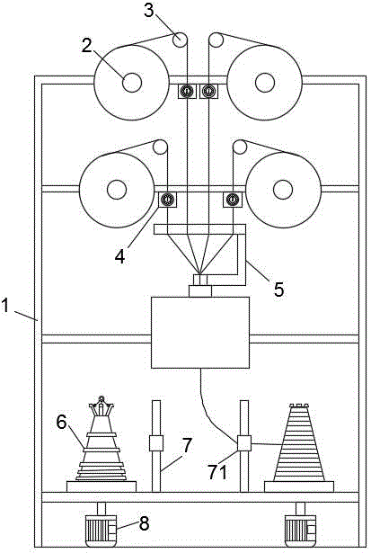
图1为本实用新型实施例中张力可调节多股捻线机的结构示意图;Fig. 1 is the structural representation of the multi-strand twister with adjustable tension in the embodiment of the utility model;
图2为本实用新型实施例中张力调节装置的主视结构示意图;Fig. 2 is the front view structure schematic diagram of the tension adjusting device in the embodiment of the utility model;
图3为本实用新型实施例中张力调节装置的剖视结构示意图;Fig. 3 is the sectional structure schematic diagram of the tension adjusting device in the embodiment of the present utility model;
图4为本实用新型实施例中过线轮的结构示意图;Fig. 4 is the structural representation of the wire passing wheel in the embodiment of the present utility model;
图5为本实用新型实施例中绕线装置的结构示意图;5 is a schematic structural diagram of a winding device in an embodiment of the present invention;
具体实施方式Detailed ways
参见图1-图5,本实施例中的张力可调节多股捻线机,包括机架1、纱筒2、导纱轮3、张力调节装置4、捻线器5、绕线装置6、导纱器7和电机8;纱筒2、导纱轮3、捻线器5、导纱器7和电机8均固定在机架1上。1-5, the tension-adjustable multi-strand twisting machine in this embodiment includes a
本实施例中的用于捻线机的张力调节装置包括定位组件、壳体41、后转盘43、前转盘44和转盘柱45;后转盘43通过轴承42转动连接在壳体41上;转盘柱45的两端分别固定在前转盘44和后转盘43上。The tension adjusting device for the twisting machine in this embodiment includes a positioning assembly, a
本实施例中的定位组件包括定位环47、定位座48、定位弹簧49和定位珠410;定位环47的一侧与前转盘44固定连接,另一侧通过轴承42与壳体41转动连接;定位环47上开有定位孔471;定位座48与壳体41的内壁固定连接;定位座48上开有盲孔;定位弹簧49固定在盲孔中;定位珠410与定位弹簧49固定连接;定位珠410与定位孔471配合;转盘柱45上还设有过线轮46;过线轮46包括上轮盘461和下轮盘462;上轮盘461和下轮盘462均套接在转盘柱45上;上轮盘461和下轮盘462上均设有用于梳理纱线的橡胶齿梳463;转盘柱45的外壁上还设有用于定位纱线的环形线槽;环形线槽位于上轮盘461和下轮盘462之间;转盘柱45的数目为2个,且2个转盘柱45相对前转盘44的中心对称设置;前转盘44上还设有便于旋转的把手441;定位环47上的定位孔471的两端孔径不同;定位孔471靠近定位座48一侧的孔径大于或等于定位珠410的直径;定位孔471远离定位座48一侧的孔径小于定位珠410的直径;定位环47上定位孔471的数目不少于12个。本实施例通过转动前转轮44上的把手441来调节纱线张力,转动把手441同时按压定位珠410从而使定位珠410依次经过定位孔471,此时转盘柱45的位置发生变动,纱线张力也随之变动,直至调节到该纱线所需张力,再开始捻线,捻线过程中由于定位珠410和定位孔471的配合,前转盘44和后转盘43都不会轻易滑动,使得捻线张力稳定。The positioning assembly in this embodiment includes a
本实施例中的绕线装置6包括底座61、线筒座62、拉环65和数个用于对绕线筒进行固定的限位扣63;底座61转动连接在机架1上,且该底座61与电机8连接;线筒座62固定在底座61上;限位扣63呈环状均匀设置在线筒座62的顶部;限位扣63的上部还设有连接环631;连接环631通过连接线64与拉环65连接。使用时,将绕线筒套在线筒座62上;由于绕线筒的形状也是下宽上窄的圆台形,所以插套时限位扣63会随着绕线筒的形状向内收,直至绕线筒完全套入线筒座62中,并与底座61接触;此时限位扣63的头部会伸出绕线筒并对其进行限位,使得绕线筒在绕线过程中无法偏移或脱离线筒座62;绕线结束后,只需拉动拉环65,使限位扣63收拢,即可将绕线完成的绕线筒取出。The
此外,需要说明的是,本说明书中所描述的具体实施例,其零、部件的形状、所取名称等可以不同,本说明书中所描述的以上内容仅仅是对本实用新型结构所作的举例说明。凡依据本实用新型专利构思所述的构造、特征及原理所做的等效变化或者简单变化,均包括于本实用新型专利的保护范围内。本实用新型所属技术领域的技术人员可以对所描述的具体实施例做各种各样的修改或补充或采用类似的方式替代,只要不偏离本实用新型的结构或者超越本权利要求书所定义的范围,均应属于本实用新型的保护范围。In addition, it should be noted that the specific embodiments described in this specification may have different shapes and names of parts and components, and the above content described in this specification is only an illustration of the structure of the present invention. All equivalent changes or simple changes made according to the structure, features and principles described in the patent concept of the present utility model are included in the protection scope of the present utility model patent. Those skilled in the art to which the present invention pertains can make various modifications or additions to the described specific embodiments or substitute in similar manners, as long as they do not deviate from the structure of the present invention or exceed those defined in the claims. All should belong to the protection scope of the present invention.
Claims (8)
Priority Applications (1)
| Application Number | Priority Date | Filing Date | Title |
|---|---|---|---|
| CN201921255452.9U CN211079456U (en) | 2019-08-05 | 2019-08-05 | Multi-strand twisting machine with adjustable tension |
Applications Claiming Priority (1)
| Application Number | Priority Date | Filing Date | Title |
|---|---|---|---|
| CN201921255452.9U CN211079456U (en) | 2019-08-05 | 2019-08-05 | Multi-strand twisting machine with adjustable tension |
Publications (1)
| Publication Number | Publication Date |
|---|---|
| CN211079456U true CN211079456U (en) | 2020-07-24 |
Family
ID=71627977
Family Applications (1)
| Application Number | Title | Priority Date | Filing Date |
|---|---|---|---|
| CN201921255452.9U Expired - Fee Related CN211079456U (en) | 2019-08-05 | 2019-08-05 | Multi-strand twisting machine with adjustable tension |
Country Status (1)
| Country | Link |
|---|---|
| CN (1) | CN211079456U (en) |
Cited By (1)
| Publication number | Priority date | Publication date | Assignee | Title |
|---|---|---|---|---|
| CN112160041A (en) * | 2020-09-28 | 2021-01-01 | 绍兴柯桥富荣纺织有限公司 | Twisting device of composite yarn for spinning |
-
2019
- 2019-08-05 CN CN201921255452.9U patent/CN211079456U/en not_active Expired - Fee Related
Cited By (1)
| Publication number | Priority date | Publication date | Assignee | Title |
|---|---|---|---|---|
| CN112160041A (en) * | 2020-09-28 | 2021-01-01 | 绍兴柯桥富荣纺织有限公司 | Twisting device of composite yarn for spinning |
Similar Documents
| Publication | Publication Date | Title |
|---|---|---|
| US3124924A (en) | System and apparatus for making elastic yarn | |
| US3742693A (en) | Yarn-twisting apparatus for formation of multiple-ply thread | |
| US2718363A (en) | Tension control device | |
| CN205634467U (en) | A tension balance adjustment device for combined cable core wire equipment | |
| CN210104162U (en) | A kind of anti-winding siro spinning wire equipment | |
| CN220224479U (en) | Twisting device for spinning processing | |
| CN103741286B (en) | One-time forming two-for-one twisting spindle | |
| TW202016378A (en) | Method for transforming a yarn spinning and/or twisting machine and a modified yarn spinning and/or twisting machine by that method | |
| US2914903A (en) | Apparatus for plying yarns | |
| US4856268A (en) | Unwinder arm rotating about a pivot suspended above a two-for-one twisting spindle for unwinding superposed bobbins | |
| CN105819276A (en) | A tension balance adjustment device for combined cable core wire equipment and its application method | |
| US2811013A (en) | Yarn twisting machine | |
| CN109881307B (en) | Double twisting and hank yarn all-in-one machine | |
| CN201473661U (en) | Twisting device for compound double-twisting | |
| US5752376A (en) | Tension-regulating rotary unwinder for a double-twist twisting frame | |
| CN211897232U (en) | A tension adjusting device for twisting machine | |
| CN218932422U (en) | Twisting machine for filiform textile threads | |
| CN105845284A (en) | A device and method for merging cable core wires | |
| US3172247A (en) | Double twist cabling apparatus | |
| CN213728601U (en) | Wire inlet guiding device of wire drawing machine | |
| CN215800109U (en) | One-step unwinding two-for-one twisting tube forming machine | |
| US3064413A (en) | Twister for fiber attenuating apparatus | |
| JPS5940929B2 (en) | double twisting device | |
| CN114084743A (en) | Hook-free high-twist twisting machine | |
| CN223592903U (en) | Yarn twisting and winding mechanism |
Legal Events
| Date | Code | Title | Description |
|---|---|---|---|
| GR01 | Patent grant | ||
| GR01 | Patent grant | ||
| CP01 | Change in the name or title of a patent holder |
Address after: 314300 Yixing Industrial Park, Wuyuan street, Haiyan County, Jiaxing City, Zhejiang Province Patentee after: Zhejiang hualijin Textile Co.,Ltd. Address before: 314300 Yixing Industrial Park, Wuyuan street, Haiyan County, Jiaxing City, Zhejiang Province Patentee before: ZHEJIANG HUALIJIN TEXTILE Co.,Ltd. |
|
| CP01 | Change in the name or title of a patent holder | ||
| CF01 | Termination of patent right due to non-payment of annual fee |
Granted publication date: 20200724 |
|
| CF01 | Termination of patent right due to non-payment of annual fee |