CN211071343U - Panel flatness correcting unit - Google Patents
Panel flatness correcting unit Download PDFInfo
- Publication number
- CN211071343U CN211071343U CN201922044950.5U CN201922044950U CN211071343U CN 211071343 U CN211071343 U CN 211071343U CN 201922044950 U CN201922044950 U CN 201922044950U CN 211071343 U CN211071343 U CN 211071343U
- Authority
- CN
- China
- Prior art keywords
- discharging
- conveying roller
- rollers
- feeding
- frame
- Prior art date
- Legal status (The legal status is an assumption and is not a legal conclusion. Google has not performed a legal analysis and makes no representation as to the accuracy of the status listed.)
- Expired - Fee Related
Links
Images


Landscapes
- Straightening Metal Sheet-Like Bodies (AREA)
Abstract
本实用新型涉及铝合金板材加工技术领域,具体涉及一种板材平面度校正装置,机架两端安装有进料输送辊组和出料输送辊组,机架顶部安装有两个气缸,两个气缸输出端与安装架固定连接,安装架下端并排设置压辊,气缸、安装架和若干压辊位于进料输送辊组和出料输送辊组之间;本实用新型通过在机架两端设置进料输送辊组和出料输送辊组,板材可一边移动一边被压平,且压平后可自动送出装置外,简化了人工推动板材或人工将板材取出的步骤,提高了工作效率,且进料从动辊与进料主动辊、出料从动辊和出料主动辊之间的间距可以调节,能够适应不同厚度的板材。
The utility model relates to the technical field of aluminum alloy plate processing, and specifically to a plate flatness correction device. A feed conveying roller group and a discharging conveying roller group are installed at both ends of a frame, two cylinders are installed on the top of the frame, the output ends of the two cylinders are fixedly connected to a mounting frame, and pressure rollers are arranged side by side at the lower end of the mounting frame. The cylinders, the mounting frame and a plurality of pressure rollers are located between the feed conveying roller group and the discharging conveying roller group. The utility model arranges the feed conveying roller group and the discharging conveying roller group at both ends of the frame, so that the plate can be flattened while moving, and can be automatically sent out of the device after being flattened, thereby simplifying the steps of manually pushing the plate or manually taking out the plate, and improving the work efficiency. The spacing between the feed driven roller and the feed active roller, the discharging driven roller and the discharging active roller can be adjusted, and can adapt to plates of different thicknesses.
Description
技术领域technical field
本实用新型涉及铝合金板材加工技术领域,更具体地说,涉及一种板材平面度校正装置。The utility model relates to the technical field of aluminum alloy plate processing, in particular to a plate flatness correction device.
背景技术Background technique
铝合金板材解决了强度、变形、重复利用等问题,但是现有的铝合金板材经过锯切、冲孔、焊接等工序后往往受加工过程因素影响,铝合金板材的平面部会出现弯曲变形,影响后续使用,因此常需要对板材的平面度进行校正,现有技术中用于铝合金板材的平面度校正装置,一般需要一般压平一边人工推动板材,操作起来费时费力,或是将板材放置校正装置中,通过移载装置移动板材,完成压合后再将板材从校正装置中取出,工作效率较低。The aluminum alloy sheet solves the problems of strength, deformation and reuse, but the existing aluminum alloy sheet is often affected by the processing process after sawing, punching, welding and other processes, and the flat part of the aluminum alloy sheet will be bent and deformed, which affects For subsequent use, it is often necessary to correct the flatness of the plate. The flatness correction device used for the aluminum alloy plate in the prior art generally needs to push the plate manually while flattening it. It is time-consuming and laborious to operate, or the plate is placed for calibration. In the device, the plate is moved by the transfer device, and the plate is taken out from the calibration device after the pressing is completed, and the work efficiency is low.
实用新型内容Utility model content
本实用新型针对现有技术的上述缺陷,提供一种板材平面度校正装置。Aiming at the above-mentioned defects of the prior art, the utility model provides a plate flatness correction device.
本实用新型解决其技术问题所采用的技术方案是:The technical scheme adopted by the utility model to solve its technical problems is:
一种板材平面度校正装置,包括机架,机架两端安装有进料输送辊组和出料输送辊组,机架顶部安装有两个气缸,两个气缸输出端均朝下设置且两者输出端与安装架固定连接,安装架下端并排设置有若干压辊,气缸、安装架和若干压辊位于进料输送辊组和出料输送辊组之间,进料输送辊组包括若干进料主动辊和位于进料主动辊上方且与进料主动辊相隔一定距离的若干进料从动辊,出料输送辊组包括若干出料主动辊和位于出料主动辊上方且与出料主动辊相隔一定距离的若干出料从动辊。A plate flatness correction device, comprising a frame, the two ends of the frame are installed with a feeding conveying roller group and a discharging conveying roller group, two air cylinders are installed on the top of the frame, and the output ends of the two air cylinders are both set downward and the two cylinders are set downward. The output end of the operator is fixedly connected with the mounting frame, and several pressing rollers are arranged side by side at the lower end of the mounting frame. The cylinder, the mounting frame and several pressing rollers are located between the feeding conveying roller group and the discharging conveying roller group. The feeding driving roller and a number of feeding driven rollers located above the feeding driving roller and separated from the feeding driving roller by a certain distance, the discharging conveying roller group includes several discharging driving rollers and a plurality of feeding driving rollers located above the discharging driving roller and connected to the discharging driving roller. Several discharge driven rollers with rollers separated by a certain distance.
更进一步地,若干进料主动辊和若干进料从动辊表面固设有橡胶层。Furthermore, rubber layers are fixed on the surfaces of several feeding driving rollers and several feeding driven rollers.
更进一步地,若干出料主动辊和若干出料从动辊表面固设有橡胶层。Furthermore, a rubber layer is fixed on the surfaces of a plurality of discharging driving rollers and a plurality of discharging driven rollers.
更进一步地,进料主动辊共两个,两个进料主动辊之间通过同步带轮组传动连接,且其中一个进料主动辊与电机输出轴连接。Further, there are two feeding driving rollers in total, and the two feeding driving rollers are connected by a synchronous pulley group, and one of the feeding driving rollers is connected with the output shaft of the motor.
更进一步地,出料主动辊共两个,两个出料主动辊之间通过同步带轮组传动连接,且其中一个出料主动辊与电机输出轴连接。Furthermore, there are a total of two discharging driving rollers, the two discharging driving rollers are connected by a synchronous pulley group, and one of the discharging driving rollers is connected with the output shaft of the motor.
更进一步地,进料从动辊两端转动设置在支撑架上,支撑架两侧固定有螺杆,机架开设有供螺杆穿过的条形通槽,螺杆贯穿条形通槽并与螺母锁紧。Further, both ends of the feed driven roller are rotated and arranged on the support frame, the two sides of the support frame are fixed with screws, the frame is provided with a bar-shaped through groove for the screw to pass through, and the screw penetrates the bar-shaped through groove and is locked with the nut. tight.
更进一步地,出料从动辊两端转动设置在支撑架上,支撑架两侧固定有螺杆,机架开设有供螺杆穿过的条形通槽,螺杆贯穿条形通槽并与螺母锁紧。Further, both ends of the discharge driven roller are rotated and arranged on the support frame, the two sides of the support frame are fixed with screws, the frame is provided with a strip-shaped through groove for the screw to pass through, and the screw penetrates through the strip-shaped through groove and is locked with the nut. tight.
本实用新型的有益效果在于:本实用新型通过在机架两端设置进料输送辊组和出料输送辊组,板材可一边移动一边被压平,且压平后可自动送出装置外,简化了人工推动板材或人工将板材取出的步骤,提高了工作效率,且进料从动辊与进料主动辊、出料从动辊和出料主动辊之间的间距可以调节,能够适应不同厚度的板材。The beneficial effect of the utility model is that: the utility model is provided with the feeding conveying roller group and the discharging conveying roller group at both ends of the frame, the plate can be flattened while moving, and can be automatically sent out of the device after being flattened, which simplifies the The steps of manually pushing the sheet or taking out the sheet are improved, and the working efficiency is improved, and the distance between the feeding driven roller and the feeding driving roller, the discharging driven roller and the discharging driving roller can be adjusted, which can adapt to different thicknesses plate.
附图说明Description of drawings
为了更清楚地说明本实用新型实施例或现有技术中的技术方案,下面将结合附图及实施例对本实用新型作进一步说明,下面描述中的附图仅仅是本实用新型的部分实施例,对于本领域普通技术人员来讲,在不付出创造性劳动的前提下,还可以根据这些附图获得其他附图:In order to more clearly illustrate the embodiments of the present utility model or the technical solutions in the prior art, the present utility model will be further described below with reference to the accompanying drawings and embodiments. The accompanying drawings in the following description are only some embodiments of the present utility model. For those of ordinary skill in the art, under the premise of no creative work, other drawings can also be obtained from these drawings:
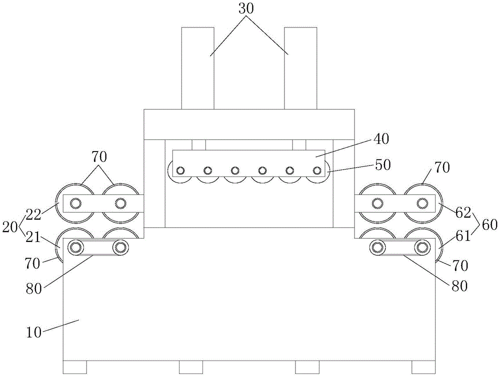
图1是本实用新型实施例一提供的一种板材平面度校正装置示意图;1 is a schematic diagram of a plate flatness correction device provided in Embodiment 1 of the present invention;
图2是本实用新型实施例二提供的一种板材平面度校正装置第一部分结构示意图;2 is a schematic structural diagram of the first part of a plate flatness correction device provided in Embodiment 2 of the present invention;
图3是本实用新型实施例二提供的一种板材平面度校正装置第二部分结构示意图。3 is a schematic structural diagram of the second part of a plate flatness correction device provided in Embodiment 2 of the present invention.
具体实施方式Detailed ways
为了使本实用新型实施例的目的、技术方案和优点更加清楚,下面将结合本实用新型实施例中的技术方案进行清楚、完整的描述,显然,所描述的实施例是本实用新型的部分实施例,而不是全部实施例。基于本实用新型的实施例,本领域普通技术人员在没有付出创造性劳动的前提下所获得的所有其他实施例,都属于本实用新型的保护范围。In order to make the purpose, technical solutions and advantages of the embodiments of the present utility model clearer, the following will describe clearly and completely the technical solutions in the embodiments of the present utility model. Obviously, the described embodiments are part of the implementation of the present utility model. examples, but not all examples. Based on the embodiments of the present invention, all other embodiments obtained by those of ordinary skill in the art without creative work fall within the protection scope of the present invention.
实施例一Example 1
本实施例一提供一种板材平面度校正装置,如图1所示,该平面度校正装置包括机架10,机架10两端安装有进料输送辊组20和出料输送辊组60,机架10顶部安装有两个气缸30,两个气缸30输出端均朝下设置且两者输出端与安装架40固定连接,安装架40下端并排设置有若干压辊50(图1中压辊的数量仅为示意,并非本实用新型所限定的数量),通过设置两个气缸30同时驱动安装架40,能够让安装架40的下压作用力更加平衡,气缸30、安装架40和若干压辊50位于进料输送辊组20和出料输送辊组60之间,进料输送辊组20包括若干进料主动辊21和位于进料主动辊21上方且与进料主动辊21相隔一定距离的若干进料从动辊22,进料从动辊22与进料主动辊21数量相同,出料输送辊组60包括若干出料主动辊61和位于出料主动辊61上方且与出料主动辊61相隔一定距离的若干出料从动辊62,出料从动辊62与出料主动辊61数量相同;将板材沿进料输送辊组20送入,气缸工作时使压辊50压在板材上,同时在进料输送辊组20的输送作用下,板材移动至出料输送辊组60处并由出料输送辊组60输送至本装置外,板材在移动过程中,在压辊50的作用下压平;若干进料主动辊21、进料从动辊22、出料主动辊61和出料从动辊62的表面固设有橡胶层70,橡胶具有一定的弹性,通过设置橡胶层70,可以增加对板材的挤压力跟摩擦力,使板材进料时的稳定性更高,并且由于橡胶具有一定的弹性,输送板材时,板材不易变形,可更好的保证板材的平面度。The first embodiment provides a plate flatness correction device. As shown in FIG. 1 , the flatness correction device includes a
本实用新型通过在机架两端设置进料输送辊组20和出料输送辊组60,板材可一边移动一边被压平,且压平后可自动送出装置外,简化了人工推动板材或人工将板材取出的步骤,提高了工作效率。In the utility model, by setting the feeding conveying
其中,本实用新型中进料主动辊21和出料主动辊61均为共两个,两个进料主动辊21之间及两个出料主动辊61之间分别通过对应的同步带轮组80传动连接,且其中一个进料主动辊21和其中一个出料主动辊61分别由与其对应的电机(图中未示)驱动,本实用新型中两个电机(分别驱动进料主动辊21和出料主动辊61)均安装在机架10上,两个电机的输出轴上固设有第一齿轮(图中未示),进料主动辊21和出料主动辊61一端上固设有第二齿轮(图中未示),第一齿轮与第二齿轮啮合,两个电机工作时,通过齿轮啮合分别使进料主动辊21和出料主动辊61转动,进料主动辊21和出料主动辊61分别通过对应的同步带轮组80传动其他进料主动辊21和出料主动辊61。Among them, in the present invention, there are two
实施例二Embodiment 2
本实施例二基于实施例一,如图2-图3所示,进料从动辊22和出料从动辊62的两端分别通过轴承座设置在对应的支撑架91上,两个支撑架91(分别与进料从动辊22和出料从动辊62对应)的两侧均固定有螺杆92,机架10开设有供螺杆92穿过的条形通槽11,条形通槽11为竖向设置,且条形通槽11与螺杆92数量相同,螺杆92贯穿条形通槽11外并与螺母93锁紧,通过旋松螺母93,即可移动螺杆92在条形通槽11中的位置,即调节进料从动辊22和出料从动辊62的高度,从而调节进料从动辊22与进料主动辊21、出料从动辊62和出料主动辊61之间的间距,以适应不同厚度的板材,调节至合适高度后旋紧螺母93即可。The second embodiment is based on the first embodiment. As shown in FIG. 2 to FIG. 3 , the two ends of the feed driven
应当理解的是,对本领域普通技术人员来说,可以根据上述说明加以改进或变换,而所有这些改进和变换都应属于本实用新型所附权利要求的保护范围。It should be understood that, for those skilled in the art, improvements or transformations can be made according to the above description, and all these improvements and transformations should belong to the protection scope of the appended claims of the present invention.
Claims (7)
Priority Applications (1)
| Application Number | Priority Date | Filing Date | Title |
|---|---|---|---|
| CN201922044950.5U CN211071343U (en) | 2019-11-22 | 2019-11-22 | Panel flatness correcting unit |
Applications Claiming Priority (1)
| Application Number | Priority Date | Filing Date | Title |
|---|---|---|---|
| CN201922044950.5U CN211071343U (en) | 2019-11-22 | 2019-11-22 | Panel flatness correcting unit |
Publications (1)
| Publication Number | Publication Date |
|---|---|
| CN211071343U true CN211071343U (en) | 2020-07-24 |
Family
ID=71633943
Family Applications (1)
| Application Number | Title | Priority Date | Filing Date |
|---|---|---|---|
| CN201922044950.5U Expired - Fee Related CN211071343U (en) | 2019-11-22 | 2019-11-22 | Panel flatness correcting unit |
Country Status (1)
| Country | Link |
|---|---|
| CN (1) | CN211071343U (en) |
Cited By (1)
| Publication number | Priority date | Publication date | Assignee | Title |
|---|---|---|---|---|
| CN112872286A (en) * | 2020-12-29 | 2021-06-01 | 广州市荻亚机电设备有限公司 | Steel plate forging equipment for manufacturing high-end equipment |
-
2019
- 2019-11-22 CN CN201922044950.5U patent/CN211071343U/en not_active Expired - Fee Related
Cited By (1)
| Publication number | Priority date | Publication date | Assignee | Title |
|---|---|---|---|---|
| CN112872286A (en) * | 2020-12-29 | 2021-06-01 | 广州市荻亚机电设备有限公司 | Steel plate forging equipment for manufacturing high-end equipment |
Similar Documents
| Publication | Publication Date | Title |
|---|---|---|
| CN109592109B (en) | An automatic film sticking device for curved screens | |
| CN205704425U (en) | Cellular board trimmer | |
| CN110406723A (en) | Overlay film laminating machine | |
| CN209649765U (en) | A printing and laminating machine with dustproof function | |
| CN106516815A (en) | Paper feeding machine suitable for conveying paper sheets with different thicknesses | |
| CN215158588U (en) | Flat plate stacking layering conveying device | |
| CN220322194U (en) | Bead-spitting firework rod skin rolling and pasting machine | |
| CN207669454U (en) | Bamboo board single-layer hot press | |
| CN214720034U (en) | A kind of punching and conveying device for aluminum plate | |
| CN212173589U (en) | Bamboo wood diversion transmission device | |
| CN209853432U (en) | A battery winding and pressing mechanism | |
| CN222905005U (en) | Edge pressing mechanism of packaging paper box pasting machine | |
| CN110000423B (en) | Steel belt dividing and cutting machine | |
| CN214687038U (en) | High frequency energy saving splicing machine | |
| CN222523755U (en) | Automatic film rolling machine | |
| CN224168391U (en) | An aluminum alloy template plane calibration device | |
| CN218836263U (en) | Galvanized sheet material blanking device | |
| CN219633967U (en) | A kind of hob cutter rubber cutting machine for rubber processing | |
| CN222138224U (en) | Feeding balance device of laminating machine | |
| CN222625818U (en) | Correcting unit that galvanized steel sheet processing was used | |
| CN223752092U (en) | A fabric foil flattening device | |
| CN112059041A (en) | Deviation correcting device for full-automatic punch feeder and using method thereof | |
| CN207495594U (en) | A kind of double layer sheet transverse cutting unit | |
| CN220461986U (en) | Auxiliary feeding device for veneer reeling machine | |
| CN214687037U (en) | High frequency splicing device |
Legal Events
| Date | Code | Title | Description |
|---|---|---|---|
| GR01 | Patent grant | ||
| GR01 | Patent grant | ||
| CF01 | Termination of patent right due to non-payment of annual fee | ||
| CF01 | Termination of patent right due to non-payment of annual fee |
Granted publication date: 20200724 |