CN211054536U - Printing device for corrugated carton processing - Google Patents
Printing device for corrugated carton processing Download PDFInfo
- Publication number
- CN211054536U CN211054536U CN201921524451.XU CN201921524451U CN211054536U CN 211054536 U CN211054536 U CN 211054536U CN 201921524451 U CN201921524451 U CN 201921524451U CN 211054536 U CN211054536 U CN 211054536U
- Authority
- CN
- China
- Prior art keywords
- roller
- printing
- bearing
- motor
- pivot
- Prior art date
- Legal status (The legal status is an assumption and is not a legal conclusion. Google has not performed a legal analysis and makes no representation as to the accuracy of the status listed.)
- Active
Links
- 239000011111 cardboard Substances 0.000 claims abstract description 25
- 230000006835 compression Effects 0.000 claims abstract description 25
- 238000007906 compression Methods 0.000 claims abstract description 25
- 230000005540 biological transmission Effects 0.000 claims abstract description 16
- 238000003466 welding Methods 0.000 claims abstract description 9
- 230000007246 mechanism Effects 0.000 claims description 7
- 239000000463 material Substances 0.000 claims description 5
- 238000003825 pressing Methods 0.000 claims description 4
- 239000000976 ink Substances 0.000 description 14
- 230000000694 effects Effects 0.000 description 4
- 239000011087 paperboard Substances 0.000 description 4
- 230000008901 benefit Effects 0.000 description 2
- 230000007613 environmental effect Effects 0.000 description 2
- 238000000034 method Methods 0.000 description 2
- 230000004075 alteration Effects 0.000 description 1
- 230000009286 beneficial effect Effects 0.000 description 1
- 238000005520 cutting process Methods 0.000 description 1
- 238000005516 engineering process Methods 0.000 description 1
- 230000001815 facial effect Effects 0.000 description 1
- 238000012986 modification Methods 0.000 description 1
- 230000004048 modification Effects 0.000 description 1
- 239000000123 paper Substances 0.000 description 1
- 230000008569 process Effects 0.000 description 1
- 238000003860 storage Methods 0.000 description 1
- 238000006467 substitution reaction Methods 0.000 description 1
Images


Landscapes
- Making Paper Articles (AREA)
Abstract
The utility model discloses a printing device is used in corrugated box processing, comprising a base plate, the equal fixed welding in upper surface left and right sides of bottom plate has two bracing pieces, four fixed welding has the frame on the bracing piece, the fixed welding in top left side of frame has first branch, there is servo electric jar through screw fixed mounting on the first roof, fixed mounting has the mounting bracket on the output axle head of servo electric jar, rotate through bearing and pivot on the mounting bracket and install the compression roller, the left side of frame is rotated through bearing and pivot and is installed down the compression roller, driven voller and drive roller pass through the conveyer belt transmission and connect, the fixed welding in top of second branch has the second roof, rotate through bearing and pivot in the printing box and install the printing roller. The utility model discloses can flatten the corrugated box cardboard, can realize printing with the corrugated box cardboard continuity, improve the printing efficiency of corrugated box cardboard.
Description
Technical Field
The utility model relates to a corrugated box processing technology field specifically is a printing device is used in corrugated box processing.
Background
Corrugated paper board is made into corrugated paper box through die cutting, impressing, nailing or adhering, which not only protects goods, is convenient for storage and transportation, but also beautifies goods and publicizes goods. The corrugated case belongs to green environmental protection product, and it does benefit to the environmental protection, does benefit to the loading and unloading transportation.
Corrugated box need print certain or several facial cardboard in the in-process of processing, however current printing apparatus mostly needs to carry out material loading, printing and unloading one by one through manual or mechanical mode, and printing efficiency is low, and if there is the fold in the surface of cardboard can influence the printing effect.
SUMMERY OF THE UTILITY MODEL
An object of the utility model is to provide a printing device is used in corrugated box processing can flatten the corrugated box cardboard, can realize the printing of corrugated box cardboard continuity ground, improves the printing efficiency of corrugated box cardboard to solve the problem that proposes in the above-mentioned background art.
In order to achieve the above object, the utility model provides a following technical scheme:
a printing device for corrugated carton processing comprises a bottom plate, wherein two support rods are fixedly welded on the left side and the right side of the upper surface of the bottom plate, a rack is fixedly welded on the four support rods, a first support rod is fixedly welded on the left side of the top end of the rack, a first top plate is fixedly welded on the top end of the first support rod, a servo electric cylinder is fixedly installed on the first top plate through screws, an output shaft of the servo electric cylinder penetrates through the first top plate, a mounting frame is fixedly installed on the head of the output shaft of the servo electric cylinder, an upper compression roller is rotatably installed on the mounting frame through a bearing and a rotating shaft, a lower compression roller is rotatably installed on the left side of the rack through the bearing and the rotating shaft, and the lower compression roller is located under;
the automatic printing machine is characterized in that a driven roller and a driving roller are rotatably mounted on the middle and the right side of the rack through bearings and rotating shafts respectively, a transmission roller is rotatably mounted on the rack through bearings and rotating shafts, the transmission roller is located in the middle of the driven roller and the driving roller, the driven roller and the driving roller are connected through a conveying belt in a transmission mode, a second supporting rod is fixedly welded on the right side of the top end of the rack, a second top plate is fixedly welded on the top end of the second supporting rod, an ink suction pump is fixedly mounted on the upper surface of the second top plate through screws, a printing box is fixedly welded on the lower surface of the second top plate, a printing roller is rotatably mounted in the printing box through bearings and rotating shafts, an ink outlet pipe is fixedly connected to an ink outlet of the ink suction pump, and an outlet of;
the bottom plate is fixedly provided with a first motor and a second motor through screws, and an output shaft of the first motor and an output shaft of the second motor are in transmission connection with a rotating shaft on the lower pressure roller and a rotating shaft on the driving roller through a transmission mechanism respectively.
Preferably, drive mechanism includes drive pulley, driven pulley and belt, drive pulley key joint is on the output shaft of first motor and the output shaft of second motor, driven pulley key joint is in the pivot on the lower compression roller and the pivot on the drive roller, drive pulley passes through the belt and is connected with the driven pulley transmission.
Preferably, the lower surface of the bottom plate is fixedly provided with a self-locking universal wheel through a bolt.
Preferably, the printing roller is positioned right above the driving roller.
Preferably, the right end of the frame is hinged with a material guide plate through a pin shaft.
Preferably, the embedded guide sleeves that have two longitudinal symmetries to set up of installing on the first roof, fixed welding has the guide bar on the upper surface of mounting bracket, guide bar sliding connection is in the guiding hole of guide sleeve.
Compared with the prior art, the beneficial effects of the utility model are that:
1. the lower compression roller is driven by the first motor to rotate, so that the corrugated case board can be flattened, the phenomenon that the corrugated case board is wrinkled during printing to influence the printing effect is avoided, the mounting frame is driven by the servo electric cylinder to move up and down, the upper compression roller is driven to move up and down, the distance between the upper compression roller and the lower compression roller is adjusted, the flattening force on the corrugated case board can be adjusted according to the thickness of the corrugated case board, and the good flattening effect is ensured;
2. drive the drive roller through the second motor and rotate, and then drive the conveyer belt and transmit the corrugated box cardboard, realize corrugated box cardboard continuity ground printing, improve the printing efficiency of corrugated box cardboard.
Drawings
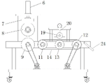
Fig. 1 is a schematic structural view of the present invention;
FIG. 2 is a schematic cross-sectional view of the present invention with the guide sleeve and guide rod removed;
fig. 3 is a schematic view of the connection between the guide sleeve and the guide rod and the first top plate of the present invention.
In the figure: 1. a base plate; 2. a support bar; 3. a frame; 4. a first support bar; 5. a first top plate; 6. a servo electric cylinder; 7. a mounting frame; 8. an upper compression roller; 9. a lower pressing roller; 10. a first motor; 11. a driven roller; 12. a drive roller; 13. a driving roller; 14. a conveyor belt; 15. a second support bar; 16. a second top plate; 17. an ink suction pump; 18. a print cartridge; 19. a printing roller; 20. an ink outlet pipe; 21. a second motor; 22. a transmission mechanism; 221. a drive pulley; 222. a driven pulley; 223. a belt; 23. a self-locking universal wheel; 24. a material guide plate; 25. a guide sleeve; 26. a guide rod.
Detailed Description
The technical solutions in the embodiments of the present invention will be described clearly and completely with reference to the accompanying drawings in the embodiments of the present invention, and it is obvious that the described embodiments are only some embodiments of the present invention, not all embodiments. Based on the embodiments in the present invention, all other embodiments obtained by a person skilled in the art without creative work belong to the protection scope of the present invention.
Referring to fig. 1-3, the present invention provides a technical solution:
a printing device for corrugated carton processing comprises a bottom plate 1, two support rods 2 are fixedly welded on the left side and the right side of the upper surface of the bottom plate 1, a rack 3 is fixedly welded on the four support rods 2, a first support rod 4 is fixedly welded on the left side of the top end of the rack 3, a first top plate 5 is fixedly welded on the top end of the first support rod 4, a servo electric cylinder 6 is fixedly installed on the first top plate 5 through screws, an output shaft of the servo electric cylinder 6 penetrates through the first top plate 5, a mounting frame 7 is fixedly installed on the end of the output shaft of the servo electric cylinder 6, an upper compression roller 8 is installed on the mounting frame 7 through a bearing and a rotating shaft in a rotating manner, a lower compression roller 9 is installed on the left side of the rack 3 through a bearing and a rotating shaft in a rotating manner, the lower compression roller 9 is positioned under the upper compression roller 8, the lower compression roller 9 is driven by a first motor 10 to rotate, the servo electric cylinder 6 drives the mounting frame 7 to move up and down, and then drives the upper compression roller 8 to move up and down, so that the distance between the upper compression roller 8 and the lower compression roller 9 can be adjusted, the flattening force of the corrugated case paper board can be adjusted according to the thickness of the corrugated case paper board, and a good flattening effect is guaranteed.
The middle part and the right side of the frame 3 are respectively provided with a driven roller 11 and a driving roller 12 through a bearing and a rotating shaft in a rotating way, the frame 3 is also provided with a driving roller 13 through a bearing and a rotating shaft in a rotating way, the driving roller 13 is positioned in the middle part of the driven roller 11 and the driving roller 12, the driven roller 11 and the driving roller 12 are connected through a conveying belt 14 in a driving way, the right side of the top end of the frame 3 is fixedly welded with a second supporting rod 15, the top end of the second supporting rod 15 is fixedly welded with a second top plate 16, the upper surface of the second top plate 16 is fixedly provided with an ink sucking pump 17 through a screw, the lower surface of the second top plate 16 is fixedly welded with a printing box 18, the printing box 18 is internally provided with a printing roller 19 through a bearing and a rotating shaft in a rotating way, the printing roller 19 is positioned right above the driving roller 13, fixedly connected with goes out china ink pipe 20 on the play china ink mouth of blotting pump 17, the export that goes out china ink pipe 20 is located printing roller 19 directly over, absorb printing ink through blotting pump 17, rethread goes out china ink pipe 20 and leads to printing roller 19 on printing the corrugated box cardboard, rethread second motor 21 drives drive roller 12 and rotates, and then drive conveyer belt 14 and transmit the corrugated box cardboard, realize the printing of corrugated box cardboard continuity, improve the printing efficiency of corrugated box cardboard.
The base plate 1 is fixedly provided with a first motor 10 and a second motor 21 through screws, and an output shaft of the first motor 10 and an output shaft of the second motor 21 are in transmission connection with a rotating shaft on the lower pressure roller 9 and a rotating shaft on the driving roller 12 through a transmission mechanism 22 respectively.
The transmission mechanism 22 comprises a driving pulley 221, a driven pulley 222 and a belt 223, the driving pulley 221 is connected to the output shaft of the first motor 10 and the output shaft of the second motor 21 in a key mode, the driven pulley 222 is connected to the rotating shaft of the lower pressure roller 9 and the rotating shaft of the driving roller 12 in a key mode, and the driving pulley 221 is in transmission connection with the driven pulley 222 through the belt 223.
The self-locking universal wheel 23 is fixedly mounted on the lower surface of the bottom plate 1 through bolts, the printing device is convenient to move, and the right end of the rack 3 is hinged with a material guide plate 24 through a pin shaft, so that the printing device can guide the corrugated case paperboard during blanking.
Two guide sleeves 25 symmetrically arranged front and back are installed on the first top plate 5 in an embedded mode, a guide rod 26 is fixedly welded on the upper surface of the mounting frame 7, the guide rod 26 is connected to the guide hole of the guide sleeves 25 in a sliding mode, when the mounting frame 7 is driven to move up and down through the servo electric cylinder 6, the guide rod 26 can slide up and down in the guide hole of the guide sleeves 25, and the stability of the mounting frame 7 in moving and fixing is guaranteed.
The working principle is as follows: during the use, power is gone up for this printing device, according to the corrugated box cardboard thickness of waiting to print, drive mounting bracket 7 through servo electric jar 6 and reciprocate, and then drive compression roller 8 and reciprocate, will go up compression roller 8 and adjust suitable distance with lower compression roller 9, drive down compression roller 9 through first motor 10 and rotate, flatten the corrugated box cardboard of process, corrugated box cardboard after flattening falls on conveyer belt 14, absorb printing ink through blotting pump 17, the rethread goes out the leading-in printing to corrugated box cardboard on printing roller 19 of ink pipe 20, corrugated box cardboard after accomplishing the printing carries out can through conveyer belt 14.
Although embodiments of the present invention have been shown and described, it will be appreciated by those skilled in the art that changes, modifications, substitutions and alterations can be made in these embodiments without departing from the principles and spirit of the invention, the scope of which is defined in the appended claims and their equivalents.
Claims (6)
1. The utility model provides a corrugated box processing is with printing device, includes bottom plate (1), its characterized in that: two support rods (2) are fixedly welded on the left side and the right side of the upper surface of the bottom plate (1), a rack (3) is fixedly welded on the four support rods (2), a first supporting rod (4) is fixedly welded on the left side of the top end of the rack (3), a first top plate (5) is fixedly welded on the top end of the first supporting rod (4), a servo electric cylinder (6) is fixedly arranged on the first top plate (5) through a screw, an output shaft of the servo electric cylinder (6) penetrates through the first top plate (5), a mounting frame (7) is fixedly mounted at the end head of the output shaft of the servo electric cylinder (6), an upper compression roller (8) is rotatably arranged on the mounting rack (7) through a bearing and a rotating shaft, a lower pressing roller (9) is rotatably arranged on the left side of the rack (3) through a bearing and a rotating shaft, and the lower pressing roller (9) is positioned right below the upper pressing roller (8);
the middle part and the right side of frame (3) rotate through bearing and pivot respectively and install driven voller (11) and drive roller (12), still rotate through bearing and pivot on frame (3) and install driving roller (13), driving roller (13) are located the middle part of driven voller (11) and drive roller (12), driven voller (11) and drive roller (12) are connected through conveyer belt (14) transmission, the top right side fixed welding of frame (3) has second branch (15), the top fixed welding of second branch (15) has second roof (16), there is blotting pump (17) through screw fixed mounting on the upper surface of second roof (16), fixed welding has printing box (18) on the lower surface of second roof (16), install printing roller (19) through bearing and pivot rotation in printing box (18), an ink outlet pipe (20) is fixedly connected to an ink outlet of the ink suction pump (17), and an outlet of the ink outlet pipe (20) is positioned right above the printing roller (19);
the automatic feeding device is characterized in that a first motor (10) and a second motor (21) are fixedly mounted on the base plate (1) through screws, and an output shaft of the first motor (10) and an output shaft of the second motor (21) are in transmission connection with a rotating shaft on the lower pressure roller (9) and a rotating shaft on the driving roller (12) through a transmission mechanism (22) respectively.
2. A printing apparatus for corrugated cardboard boxes according to claim 1, wherein: drive mechanism (22) are including drive pulley (221), driven pulley (222) and belt (223), drive pulley (221) key joint is on the output shaft of first motor (10) and the output shaft of second motor (21), driven pulley (222) key joint is in the pivot on lower compression roller (9) and the pivot on drive roller (12), drive pulley (221) are through belt (223) and driven pulley (222) transmission connection.
3. A printing apparatus for corrugated cardboard boxes according to claim 1, wherein: and the lower surface of the bottom plate (1) is fixedly provided with a self-locking universal wheel (23) through a bolt.
4. A printing apparatus for corrugated cardboard boxes according to claim 1, wherein: the printing roller (19) is positioned right above the driving roller (13).
5. A printing apparatus for corrugated cardboard boxes according to claim 1, wherein: the right end of the frame (3) is hinged with a material guide plate (24) through a pin shaft.
6. A printing apparatus for corrugated cardboard boxes according to claim 1, wherein: the embedded guide sleeve (25) that set up of two front and back symmetries of installing on first roof (5), fixed welding has guide bar (26) on the upper surface of mounting bracket (7), guide bar (26) sliding connection is in the guiding hole of guide sleeve (25).
Priority Applications (1)
| Application Number | Priority Date | Filing Date | Title |
|---|---|---|---|
| CN201921524451.XU CN211054536U (en) | 2019-09-15 | 2019-09-15 | Printing device for corrugated carton processing |
Applications Claiming Priority (1)
| Application Number | Priority Date | Filing Date | Title |
|---|---|---|---|
| CN201921524451.XU CN211054536U (en) | 2019-09-15 | 2019-09-15 | Printing device for corrugated carton processing |
Publications (1)
| Publication Number | Publication Date |
|---|---|
| CN211054536U true CN211054536U (en) | 2020-07-21 |
Family
ID=71593324
Family Applications (1)
| Application Number | Title | Priority Date | Filing Date |
|---|---|---|---|
| CN201921524451.XU Active CN211054536U (en) | 2019-09-15 | 2019-09-15 | Printing device for corrugated carton processing |
Country Status (1)
| Country | Link |
|---|---|
| CN (1) | CN211054536U (en) |
Cited By (1)
| Publication number | Priority date | Publication date | Assignee | Title |
|---|---|---|---|---|
| CN111805975A (en) * | 2020-07-24 | 2020-10-23 | 周俊杰 | Corrugated packaging carton manufacturing, forming and processing machine and forming and processing technology |
-
2019
- 2019-09-15 CN CN201921524451.XU patent/CN211054536U/en active Active
Cited By (1)
| Publication number | Priority date | Publication date | Assignee | Title |
|---|---|---|---|---|
| CN111805975A (en) * | 2020-07-24 | 2020-10-23 | 周俊杰 | Corrugated packaging carton manufacturing, forming and processing machine and forming and processing technology |
Similar Documents
| Publication | Publication Date | Title |
|---|---|---|
| CN110255258B (en) | Paper collecting and arranging device for printing machine | |
| CN211641656U (en) | Embossing device of accessory | |
| CN221622372U (en) | Paper machine is divided to thin blade line ball | |
| CN218434109U (en) | Post-processing device for producing single-corrugated double-layer paperboard | |
| CN215321395U (en) | Heating device for die-cutting stamping machine | |
| CN216548703U (en) | Paper printing leveling device for printing machine | |
| CN214720034U (en) | Aluminum plate's die-cut conveyor | |
| CN216127583U (en) | Automatic production line of vulcanizing machine | |
| CN213321245U (en) | Panel location edge scraping machine | |
| CN213798337U (en) | Automatic energy-saving glue adding device for box pasting machine | |
| CN211593156U (en) | A kind of glue coating equipment for carton packaging | |
| CN220763702U (en) | Corrugated box folding forming machine | |
| CN221253191U (en) | Feeding structure and green printing product inspection machine with same | |
| CN218619316U (en) | Make things convenient for high-speed machine of pasting of material loading to glue | |
| CN224089773U (en) | Corrugated box production is with rolling over device | |
| CN219155959U (en) | Feeding device for printer for vertically placing corrugated boards | |
| CN219749029U (en) | Automatic overturning device of box sticking machine | |
| CN213733639U (en) | Full-automatic paper board color printing laminating machine | |
| CN221214825U (en) | Material conveying mechanism of packaging box printing machine | |
| CN221953973U (en) | Automatic gluing device for carton production | |
| CN222410101U (en) | Feeding and discharging device for platen press indentation line cutting machine | |
| CN216885396U (en) | Paper feeding device additionally arranged for paperboard box pasting machine | |
| CN220075898U (en) | Environment-friendly printing and dyeing equipment for environment-friendly color boxes | |
| CN219727327U (en) | Carton printing and feeding device | |
| CN222061383U (en) | A box gluer for carton production |
Legal Events
| Date | Code | Title | Description |
|---|---|---|---|
| GR01 | Patent grant | ||
| GR01 | Patent grant |