CN211051041U - Novel electric power signboard - Google Patents
Novel electric power signboard Download PDFInfo
- Publication number
- CN211051041U CN211051041U CN201921694240.0U CN201921694240U CN211051041U CN 211051041 U CN211051041 U CN 211051041U CN 201921694240 U CN201921694240 U CN 201921694240U CN 211051041 U CN211051041 U CN 211051041U
- Authority
- CN
- China
- Prior art keywords
- hole
- adjusting
- signboard
- rod
- sign
- Prior art date
- Legal status (The legal status is an assumption and is not a legal conclusion. Google has not performed a legal analysis and makes no representation as to the accuracy of the status listed.)
- Expired - Fee Related
Links
Images


Landscapes
- Filtration Of Liquid (AREA)
Abstract
本实用新型属于电力设备技术领域,尤其是一种新型电力标识牌,针对现有的标识主体在户外使用时,灰尘极易容易随着雨水一同流入雨水储箱内,致使雨水使用清洁标识牌表面时达不到清理效果,还容易损坏抽水泵的缺点,而提出如下方案,其包括标识主体,标识主体的一侧设有标识牌,标识主体内设有储水箱,储水箱的一侧连接有集水盒,所述标识主体的顶侧开设有集水槽,集水槽的底侧内壁上开设有沉淀槽,储水箱的顶侧连接有进水管。本实用新型结构简单,雨水收集时过滤网有效的将灰尘杂物过滤掉,灰尘杂物沉积在收集盒内以便集中取出清理,保证了雨水利用时的安全性,同时过滤网清理方便不易堵塞,满足了使用需求。
The utility model belongs to the technical field of electric equipment, in particular to a novel electric power sign. When the existing sign body is used outdoors, dust easily flows into the rainwater storage tank together with the rainwater, so that the rainwater can be used to clean the surface of the signboard. When the cleaning effect is not achieved, and the pump is easily damaged, the following scheme is proposed, which includes a main body of the sign, one side of the main body of the sign is provided with a sign, a water storage tank is arranged in the main body of the sign, and one side of the water storage tank is connected with a In the water collecting box, a water collecting tank is opened on the top side of the marking body, a sedimentation tank is opened on the inner wall of the bottom side of the water collecting tank, and a water inlet pipe is connected to the top side of the water storage tank. The utility model has a simple structure, the filter net can effectively filter out the dust and sundries during the rainwater collection, and the dust and sundries are deposited in the collection box for centralized removal and cleaning, which ensures the safety of rainwater utilization, and at the same time, the filter net is easy to clean and not easy to be blocked. meet the needs of use.
Description
技术领域technical field
本实用新型涉及电力设备技术领域,尤其涉及一种新型电力标识牌。The utility model relates to the technical field of electric equipment, in particular to a novel electric power identification plate.
背景技术Background technique
在进行道路施工或者电力高压警示时,人们通常会设置电力标识牌警示人们减速慢行或者绕道行驶,路面设置的标识牌结构较为简单且直接固定在某一位置移动起来十分不便;现有的电力标识牌在使用的时候存在一定的弊端,当发现标识牌的表面被污物覆盖,无法立即进行清理,且标识牌直接暴露在外,很容易受到太阳的暴晒与雨水冲刷,导致表面标识损坏。When carrying out road construction or high-voltage warning of electric power, people usually set up electric signs to warn people to slow down or detour. There are certain drawbacks in the use of signboards. When it is found that the surface of the signboard is covered with dirt, it cannot be cleaned immediately, and the signboard is directly exposed, which is easily exposed to the sun and rain, resulting in damage to the surface marking.
公开号为CN208422253U的专利公开了一种便捷电力标识牌,包括主体外壳,所述主体外壳的前端外表面固定安装有警示标识主体,设有清理结构、遮挡板与限位杆,能够对警示标识表面进行清洁,减少日晒雨淋对该装置的损坏,还可以调节该装置的高度并进行有效的固定,但是标识主体在户外使用时,灰尘极易容易随着雨水一同流入雨水储箱内,致使雨水使用清洁标识牌表面时达不到清理效果,还容易损坏抽水泵,因此有改进空间。The patent with publication number CN208422253U discloses a convenient power sign, including a main body shell, the front end outer surface of the main body shell is fixedly installed with a warning sign main body, and is provided with a cleaning structure, a shielding plate and a limit rod, which can detect the warning signs. The surface is cleaned to reduce the damage to the device from the sun and rain, and the height of the device can also be adjusted and effectively fixed. However, when the main body of the sign is used outdoors, the dust easily flows into the rainwater storage tank along with the rainwater. As a result, the cleaning effect cannot be achieved when the rainwater is used to clean the surface of the sign, and it is also easy to damage the pump, so there is room for improvement.
实用新型内容Utility model content
本实用新型的目的是为了解决现有技术中存在标识主体在户外使用时,灰尘极易容易随着雨水一同流入雨水储箱内,致使雨水使用清洁标识牌表面时达不到清理效果,还容易损坏抽水泵的缺点,而提出的一种新型电力标识牌。The purpose of this utility model is to solve the problem that when the main body of the sign in the prior art is used outdoors, the dust easily flows into the rainwater storage tank together with the rainwater, so that the cleaning effect cannot be achieved when the rainwater is used to clean the surface of the signboard, and it is easy to A new type of electric power sign is proposed to damage the shortcomings of the water pump.
为了实现上述目的,本实用新型采用了如下技术方案:In order to achieve the above-mentioned purpose, the utility model adopts the following technical solutions:
一种新型电力标识牌,包括标识主体,标识主体的一侧设有标识牌,标识主体内设有储水箱,储水箱的一侧连接有集水盒,所述标识主体的顶侧开设有集水槽,集水槽的底侧内壁上开设有沉淀槽,储水箱的顶侧连接有进水管,进水管与沉淀槽相互靠近的一侧内壁上开设有同一个溢流孔,溢流孔的顶侧和底侧内壁上固定安装有同一个过滤网,沉淀槽的底侧内壁上放置有收集盒,沉淀槽的一侧内壁上开设有位于溢流孔正上方的调节孔,调节孔内转动安装有调节轴,调节轴的两端均延伸至调节孔外,调节轴的一端固定安装有位于沉淀槽内的安装杆,调节轴的另一端固定安装有把手,安装杆靠近过滤网的一侧安装有清洁刷,清洁刷与过滤网的一侧相接触,溢流孔内设置过滤网,灰尘杂物不会进入储水箱内,保证了雨水利用时的安全性,沉淀槽内放置有收集盒,灰尘杂物会沉积在收集盒内,以便集中取出清理。A new type of electric power sign, comprising a sign main body, a sign plate is arranged on one side of the sign main body, a water storage tank is arranged in the sign main body, a water collecting box is connected to one side of the water storage tank, and a water collecting box is opened on the top side of the sign main body. The bottom side of the water tank is provided with a sedimentation tank, the top side of the water storage tank is connected with a water inlet pipe, and the same overflow hole is opened on the inner wall of the side where the water inlet pipe and the sedimentation tank are close to each other, and the top side of the overflow hole The same filter screen is fixedly installed on the inner wall of the bottom side, a collection box is placed on the inner wall of the bottom side of the sedimentation tank, and an adjustment hole located directly above the overflow hole is opened on the inner wall of one side of the sedimentation tank. Adjusting shaft, both ends of the adjusting shaft extend to the outside of the adjusting hole, one end of the adjusting shaft is fixedly installed with an installation rod located in the sedimentation tank, the other end of the adjusting shaft is fixedly installed with a handle, and the side of the installation rod close to the filter screen is installed with a The cleaning brush is in contact with one side of the filter screen, and the filter screen is set in the overflow hole, so that dust and debris will not enter the water storage tank, which ensures the safety of rainwater utilization. Debris will be deposited in the collection box for centralized removal and cleaning.
优选的,所述溢流孔的顶侧内壁上开设有移动孔,移动孔与调节孔相连通,移动孔内活动安装有调节杆,调节轴上开设有环形的推拉槽,推拉槽为倾斜设置,调节杆的顶端延伸至推拉槽内,调节杆的底端延伸至溢流孔内并固定安装有撞击杆,撞击杆与过滤网远离清洁刷的一侧相接触,过滤网被堵塞时,只需拨动把手,带动安装杆及清洁刷摆动,清洁刷将过滤网左侧堆积的灰尘杂物刮下,同时撞击杆撞击过滤网使其抖动,进一步将网孔内的杂物抖落。Preferably, a moving hole is formed on the inner wall of the top side of the overflow hole, the moving hole is communicated with the adjusting hole, an adjusting rod is movably installed in the moving hole, and an annular push-pull groove is formed on the adjusting shaft, and the push-pull groove is inclined. , the top end of the adjustment rod extends into the push-pull groove, the bottom end of the adjustment rod extends into the overflow hole, and the impact rod is fixedly installed. The impact rod is in contact with the side of the filter screen away from the cleaning brush. When the filter screen is blocked, only The handle needs to be turned to drive the installation rod and the cleaning brush to swing. The cleaning brush scrapes off the dust and debris accumulated on the left side of the filter screen, and at the same time, the impact rod hits the filter screen to make it shake, further shaking off the debris in the mesh.
优选的,所述调节杆的一侧沿水平方向开设有位于移动孔内的限位孔,限位孔内滑动安装有支撑杆,支撑杆的两端分别固定安装在移动孔的两侧内壁上,对调节杆限位。Preferably, one side of the adjusting rod is provided with a limit hole located in the moving hole along the horizontal direction, a support rod is slidably installed in the limit hole, and both ends of the support rod are fixedly installed on the inner walls of both sides of the moving hole respectively. , to limit the adjustment rod.
优选的,所述调节杆远离清洁刷的一侧固定安装有弹簧的一端,弹簧的另一端固定安装在移动孔远离清洁刷的一侧内壁上,便于自动复位。Preferably, one end of the spring is fixedly installed on the side of the adjusting rod away from the cleaning brush, and the other end of the spring is fixedly installed on the inner wall of the side of the moving hole away from the cleaning brush, so as to facilitate automatic reset.
优选的,所述调节轴上活动套接有位于调节孔内的密封圈,密封圈与调节孔的内壁相接触,保证密封性。Preferably, a sealing ring located in the adjusting hole is movably sleeved on the adjusting shaft, and the sealing ring is in contact with the inner wall of the adjusting hole to ensure sealing.
与现有的技术相比,本实用新型的有益效果是:Compared with the prior art, the beneficial effects of the present utility model are:
溢流孔内设置过滤网,灰尘杂物不会进入储水箱内,保证了雨水利用时的安全性,沉淀槽内放置有收集盒,灰尘杂物会沉积在收集盒内,以便集中取出清理;A filter screen is set in the overflow hole, so that dust and debris will not enter the water storage tank, which ensures the safety of rainwater utilization. A collection box is placed in the sedimentation tank, and the dust and debris will be deposited in the collection box for centralized removal and cleaning;
过滤网被堵塞时,只需拨动把手,带动安装杆及清洁刷摆动,清洁刷将过滤网左侧堆积的灰尘杂物刮下,同时撞击杆撞击过滤网使其抖动,进一步将网孔内的杂物抖落;When the filter screen is blocked, you only need to turn the handle to drive the installation rod and the cleaning brush to swing. the debris shakes off;
本实用新型结构简单,雨水收集时过滤网有效的将灰尘杂物过滤掉,灰尘杂物沉积在收集盒内以便集中取出清理,保证了雨水利用时的安全性,同时过滤网清理方便不易堵塞,满足了使用需求。The utility model has a simple structure, the filter net effectively filters out the dust and sundries during the rainwater collection, and the dust and sundries are deposited in the collection box for centralized removal and cleaning, which ensures the safety of rainwater utilization, and at the same time, the filter net is easy to clean and is not easy to be blocked. meet the needs of use.
附图说明Description of drawings
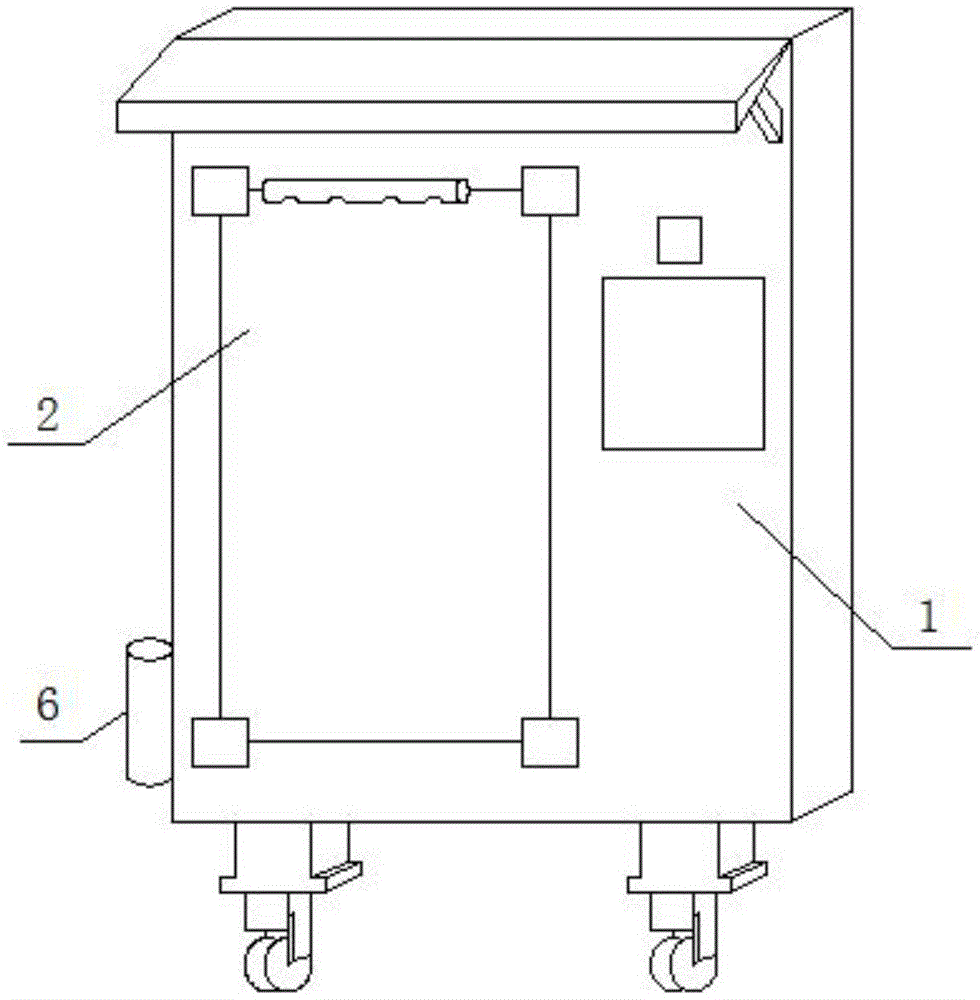
图1为本实用新型提出的一种新型电力标识牌的立体结构示意图;Fig. 1 is the three-dimensional structure schematic diagram of a kind of novel electric power signboard proposed by the utility model;
图2为本实用新型提出的一种新型电力标识牌的正视部分结构示意图;Fig. 2 is the front view partial structure schematic diagram of a kind of novel electric power signboard proposed by the utility model;
图3为本实用新型提出的一种新型电力标识牌图2中A部分的结构示意图;Fig. 3 is the structural representation of part A in Fig. 2 of a new type of electric power signboard proposed by the utility model;
图4为本实用新型提出的一种新型电力标识牌图3中A1部分的结构示意图。FIG. 4 is a schematic structural diagram of part A1 in FIG. 3 of a new type of power identification plate proposed by the utility model.
图中:1标识主体、2标识牌、3集水槽、4沉淀槽、5储水箱、6集水盒、7进水管、8溢流孔、9过滤网、10收集盒、11调节孔、12调节轴、13把手、14安装杆、15清洁刷、16移动孔、17推拉槽、18调节杆、19撞击杆、20支撑杆、21限位孔、22密封圈。In the picture: 1 logo main body, 2 identification plate, 3 water collection tank, 4 sedimentation tank, 5 water storage tank, 6 water collection box, 7 water inlet pipe, 8 overflow hole, 9 filter screen, 10 collection box, 11 adjustment hole, 12 Adjustment shaft, 13 handle, 14 installation rod, 15 cleaning brush, 16 moving hole, 17 push-pull groove, 18 adjustment rod, 19 impact rod, 20 support rod, 21 limit hole, 22 seal ring.
具体实施方式Detailed ways
下面将结合本实用新型实施例中的附图,对本实用新型实施例中的技术方案进行清楚、完整地描述,显然,所描述的实施例仅仅是本实用新型一部分实施例,而不是全部的实施例。The technical solutions in the embodiments of the present utility model will be clearly and completely described below with reference to the accompanying drawings in the embodiments of the present utility model. Obviously, the described embodiments are only a part of the embodiments of the present utility model, rather than all the implementations. example.
实施例一Example 1
参照图1-4,一种新型电力标识牌,包括标识主体1,标识主体1的一侧设有标识牌2,标识主体1内设有储水箱5,储水箱5的一侧连接有集水盒6,标识主体1的顶侧开设有集水槽3,集水槽3的底侧内壁上开设有沉淀槽4,储水箱5的顶侧连接有进水管7,进水管7与沉淀槽4相互靠近的一侧内壁上开设有同一个溢流孔8,溢流孔8的顶侧和底侧内壁上固定安装有同一个过滤网9,沉淀槽4的底侧内壁上放置有收集盒10,沉淀槽4的一侧内壁上开设有位于溢流孔8正上方的调节孔11,调节孔11内转动安装有调节轴12,调节轴12的两端均延伸至调节孔11外,调节轴12的一端固定安装有位于沉淀槽4内的安装杆14,调节轴12的另一端固定安装有把手13,安装杆14靠近过滤网9的一侧安装有清洁刷15,清洁刷15与过滤网9的一侧相接触,溢流孔8内设置过滤网,灰尘杂物不会进入储水箱5内,保证了雨水利用时的安全性,沉淀槽4内放置有收集盒10,灰尘杂物会沉积在收集盒10内,以便集中取出清理。Referring to Figures 1-4, a new type of electric power signboard includes a
本实用新型中,溢流孔8的顶侧内壁上开设有移动孔16,移动孔16与调节孔11相连通,移动孔16内活动安装有调节杆18,调节轴12上开设有环形的推拉槽17,推拉槽17为倾斜设置,调节杆18的顶端延伸至推拉槽17内,调节杆18的底端延伸至溢流孔8内并固定安装有撞击杆19,撞击杆19与过滤网9远离清洁刷15的一侧相接触,过滤网9被堵塞时,只需拨动把手13,带动安装杆14及清洁刷15摆动,清洁刷15将过滤网9左侧堆积的灰尘杂物刮下,同时撞击杆19撞击过滤网9使其抖动,进一步将网孔内的杂物抖落。In the utility model, a moving
本实用新型中,调节杆18的一侧沿水平方向开设有位于移动孔16内的限位孔21,限位孔21内滑动安装有支撑杆20,支撑杆20的两端分别固定安装在移动孔16的两侧内壁上,对调节杆18限位。In the present invention, one side of the adjusting
本实用新型中,调节杆18远离清洁刷15的一侧固定安装有弹簧的一端,弹簧的另一端固定安装在移动孔16远离清洁刷15的一侧内壁上,便于自动复位。In the present invention, one end of the spring is fixedly installed on the side of the adjusting
本实用新型中,调节轴12上活动套接有位于调节孔11内的密封圈22,密封圈22与调节孔11的内壁相接触,保证密封性。In the present invention, the adjusting
实施例二
参照图1-4,一种新型电力标识牌,包括标识主体1,标识主体1的一侧设有标识牌2,标识主体1内设有储水箱5,储水箱5的一侧连接有集水盒6,标识主体1的顶侧开设有集水槽3,集水槽3的底侧内壁上开设有沉淀槽4,储水箱5的顶侧连接有进水管7,进水管7与沉淀槽4相互靠近的一侧内壁上开设有同一个溢流孔8,溢流孔8的顶侧和底侧内壁上通过焊接方式固定安装有同一个过滤网9,沉淀槽4的底侧内壁上放置有收集盒10,沉淀槽4的一侧内壁上开设有位于溢流孔8正上方的调节孔11,调节孔11内转动安装有调节轴12,调节轴12的两端均延伸至调节孔11外,调节轴12的一端通过焊接方式固定安装有位于沉淀槽4内的安装杆14,调节轴12的另一端通过焊接方式固定安装有把手13,安装杆14靠近过滤网9的一侧安装有清洁刷15,清洁刷15与过滤网9的一侧相接触,溢流孔8内设置过滤网,灰尘杂物不会进入储水箱5内,保证了雨水利用时的安全性,沉淀槽4内放置有收集盒10,灰尘杂物会沉积在收集盒10内,以便集中取出清理。Referring to Figures 1-4, a new type of electric power signboard includes a
本实用新型中,溢流孔8的顶侧内壁上开设有移动孔16,移动孔16与调节孔11相连通,移动孔16内活动安装有调节杆18,调节轴12上开设有环形的推拉槽17,推拉槽17为倾斜设置,调节杆18的顶端延伸至推拉槽17内,调节杆18的底端延伸至溢流孔8内并通过焊接方式固定安装有撞击杆19,撞击杆19与过滤网9远离清洁刷15的一侧相接触,过滤网9被堵塞时,只需拨动把手13,带动安装杆14及清洁刷15摆动,清洁刷15将过滤网9左侧堆积的灰尘杂物刮下,同时撞击杆19撞击过滤网9使其抖动,进一步将网孔内的杂物抖落。In the utility model, a moving
本实用新型中,调节杆18的一侧沿水平方向开设有位于移动孔16内的限位孔21,限位孔21内滑动安装有支撑杆20,支撑杆20的两端分别通过焊接方式固定安装在移动孔16的两侧内壁上,对调节杆18限位。In the present invention, one side of the adjusting
本实用新型中,调节杆18远离清洁刷15的一侧通过焊接方式固定安装有弹簧的一端,弹簧的另一端通过焊接方式固定安装在移动孔16远离清洁刷15的一侧内壁上,便于自动复位。In the present invention, the side of the adjusting
本实用新型中,调节轴12上活动套接有位于调节孔11内的密封圈22,密封圈22与调节孔11的内壁相接触,保证密封性。In the present invention, the adjusting
本实用新型中,雨水收集时,雨水顺着倾斜设置的集水槽3流入沉淀槽4内,再经过滤网9过滤掉灰尘杂物后,由溢流孔8和进水管7收集在储水箱5内,集水盒6可以观察储水箱5的液位,溢流孔8内设置过滤网,灰尘杂物不会进入储水箱5内,保证了雨水利用时的安全性,沉淀槽4内放置有收集盒10,灰尘杂物会沉积在收集盒10内,以便集中取出清理,过滤网9被堵塞时,只需拨动把手13,带动调节轴12摆动半周,调节轴12带动安装杆14及清洁刷15摆动,清洁刷15将过滤网9左侧堆积的灰尘杂物刮下,调节轴12转动过程中,环形倾斜设置的推拉槽17的内壁不断的推挤调节杆18,在限位孔21的限位作用下,调节杆18右移并压缩弹簧,撞击杆19一同右移并与过滤网9的右侧分离,松开把手13后,在弹簧的反弹作用下,调节杆18左移复位,带动调节轴12及清洁刷15反转复位,同时撞击杆19撞击过滤网9使其抖动,进一步将网孔内的杂物抖落,清理十分方便。In the utility model, when rainwater is collected, the rainwater flows into the
以上所述,仅为本实用新型较佳的具体实施方式,但本实用新型的保护范围并不局限于此,任何熟悉本技术领域的技术人员在本实用新型揭露的技术范围内,根据本实用新型的技术方案及其实用新型构思加以等同替换或改变,都应涵盖在本实用新型的保护范围之内。The above description is only a preferred embodiment of the present invention, but the protection scope of the present invention is not limited to this. Equivalent replacement or modification of the new technical solution and its utility model concept shall be included within the protection scope of the present utility model.
Claims (5)
Priority Applications (1)
| Application Number | Priority Date | Filing Date | Title |
|---|---|---|---|
| CN201921694240.0U CN211051041U (en) | 2019-10-11 | 2019-10-11 | Novel electric power signboard |
Applications Claiming Priority (1)
| Application Number | Priority Date | Filing Date | Title |
|---|---|---|---|
| CN201921694240.0U CN211051041U (en) | 2019-10-11 | 2019-10-11 | Novel electric power signboard |
Publications (1)
| Publication Number | Publication Date |
|---|---|
| CN211051041U true CN211051041U (en) | 2020-07-21 |
Family
ID=71587008
Family Applications (1)
| Application Number | Title | Priority Date | Filing Date |
|---|---|---|---|
| CN201921694240.0U Expired - Fee Related CN211051041U (en) | 2019-10-11 | 2019-10-11 | Novel electric power signboard |
Country Status (1)
| Country | Link |
|---|---|
| CN (1) | CN211051041U (en) |
Cited By (2)
| Publication number | Priority date | Publication date | Assignee | Title |
|---|---|---|---|---|
| CN113426760A (en) * | 2021-07-09 | 2021-09-24 | 杨学 | Remove atomizing clearance dust equipment |
| CN118899755A (en) * | 2024-07-18 | 2024-11-05 | 博时达集团有限公司 | Environmentally friendly power distribution cabinet |
-
2019
- 2019-10-11 CN CN201921694240.0U patent/CN211051041U/en not_active Expired - Fee Related
Cited By (2)
| Publication number | Priority date | Publication date | Assignee | Title |
|---|---|---|---|---|
| CN113426760A (en) * | 2021-07-09 | 2021-09-24 | 杨学 | Remove atomizing clearance dust equipment |
| CN118899755A (en) * | 2024-07-18 | 2024-11-05 | 博时达集团有限公司 | Environmentally friendly power distribution cabinet |
Similar Documents
| Publication | Publication Date | Title |
|---|---|---|
| CN110604952B (en) | An automatic dredging device for sewage filtration | |
| CN213784561U (en) | Irrigation equipment who has rainwater collection mechanism is used in gardens | |
| CN106016101A (en) | System for cleaning streetlamp through raindrops | |
| CN107091436A (en) | A kind of street lamp provided with screw rod automated cleaning | |
| CN217150966U (en) | A kind of building structure design roof cornice waterproof structure | |
| CN217949560U (en) | Architectural design roof eaves mouth waterproof construction | |
| CN207583025U (en) | Swimming pool bottom foreign matter automatic cleaning machine | |
| CN210187780U (en) | Clear up sill device | |
| CN211849179U (en) | Road cleaning dust collector for bridge construction | |
| CN109604213B (en) | A environmental protection belt cleaning device for camera | |
| CN105317075B (en) | Rain collector | |
| CN209989682U (en) | Road surface maintenance watering device | |
| CN218672537U (en) | Intelligent purification ventilation workstation | |
| CN218589823U (en) | A Municipal Road Drainage Filtration System | |
| CN214914380U (en) | Energy-saving dust removal removes flavor fan | |
| CN216256266U (en) | A self-cleaning public seat | |
| CN211646553U (en) | Green building rainwater collection auxiliary device | |
| CN210979666U (en) | L ED solar street lamp with protector | |
| CN208785962U (en) | A rainwater filter | |
| CN223805676U (en) | A municipal pipeline anti-clogging and sewage interception structure | |
| CN219922261U (en) | High-efficiency environment-friendly water treatment device | |
| CN215675083U (en) | Dust type has video instant music's wisdom lamp pole | |
| CN220272099U (en) | A kind of rain cover for advertising light box | |
| CN219240831U (en) | A kind of urban waterlogging drainage grid cleaning machine | |
| CN217651966U (en) | Be applicable to ecological gardens structure in sponge city |
Legal Events
| Date | Code | Title | Description |
|---|---|---|---|
| GR01 | Patent grant | ||
| GR01 | Patent grant | ||
| CF01 | Termination of patent right due to non-payment of annual fee | ||
| CF01 | Termination of patent right due to non-payment of annual fee |
Granted publication date: 20200721 |