CN211041019U - Activated carbon adsorption desorption catalytic combustion equipment - Google Patents
Activated carbon adsorption desorption catalytic combustion equipment Download PDFInfo
- Publication number
- CN211041019U CN211041019U CN201922064758.2U CN201922064758U CN211041019U CN 211041019 U CN211041019 U CN 211041019U CN 201922064758 U CN201922064758 U CN 201922064758U CN 211041019 U CN211041019 U CN 211041019U
- Authority
- CN
- China
- Prior art keywords
- adsorption
- desorption
- shell
- filtering
- frame
- Prior art date
- Legal status (The legal status is an assumption and is not a legal conclusion. Google has not performed a legal analysis and makes no representation as to the accuracy of the status listed.)
- Active
Links
Images


Abstract
An activated carbon adsorption and desorption catalytic combustion device comprises a pretreatment device, an adsorption and desorption device, a combustion furnace, a heat recovery device and an exhaust tower, wherein the pretreatment device comprises a first shell, the bottom of the first shell is detachably connected with a water receiving tank, the water receiving tank is provided with a liquid discharge port, and a first filtering device is arranged above the water receiving tank; the first filtering device comprises a first filtering frame and a supporting plate, the supporting plate is arranged in the first filtering frame, a filtering net is arranged between the first filtering frame and the supporting plate, and the first filtering frame is detachably and fixedly connected with the first shell; fixedly connected with conveyer pipe between the top of first filter equipment and first casing, first casing external fixation has the pump, pump and conveyer pipe intercommunication, and the conveyer pipe overcoat is equipped with the annular spray pipe, and the annular spray pipe passes through the connecting pipe intercommunication with the conveyer pipe, all is equipped with a plurality of on annular spray pipe and the connecting pipe and sprays the mouth. The utility model discloses can purify the waste liquid that produces among the pre treatment facilities, avoid direct emission, polluted environment.
Description
Technical Field
The utility model relates to a technical field of absorption desorption catalytic combustion equipment, concretely relates to active carbon adsorption desorption catalytic combustion equipment.
Background
Activated carbon adsorption desorption catalytic combustion equipment is the equipment that activated carbon adsorption and thermal oxidation combine together organically, mainly include preprocessing equipment, adsorb desorption equipment, fire burning furnace, heat recovery equipment and exhaust tower, preprocessing equipment is arranged in taking out particle impurity such as dust in the waste gas, adsorb desorption equipment including the active carbon adsorption layer, be used for adsorbing waste gas, fire burning furnace and be used for burning or oxidizing organic waste gas, heat recovery equipment is used for retrieving the heat of burning furnace, the exhaust tower is arranged in discharging clean air to the atmosphere.
The equipment is suitable for occasions with large air volume and low concentration which are not suitable for being treated by a direct combustion method, a UV photo-oxygen catalysis method and other methods, and the basic principle is that the low-concentration organic waste gas is absorbed by utilizing the adsorption characteristic of activated carbon and then is converted into the small-air-volume high-concentration organic waste gas through desorption. Concentrated organic waste gas more than tens of times gets into the combustion furnace that contains the catalyst and carries out low temperature combustion or oxidation treatment to partly pass through heat recovery equipment retrieval and utilization with the heat that organic matter burning released, be used for the desorption of active carbon, the active carbon of being convenient for continues to adsorb waste gas, this type equipment is for other organic waste gas treatment equipment, and the treatment effeciency is higher.
The pretreatment equipment adopts a spraying method to effectively remove dust and other particle impurities in the waste gas, but generates waste liquid which is directly discharged and pollutes the environment.
SUMMERY OF THE UTILITY MODEL
The utility model aims to provide a: the utility model provides an active carbon adsorbs desorption catalytic combustion equipment, can purify the waste liquid that produces in the preprocessing equipment, avoids direct emission, polluted environment.
The utility model discloses the technical scheme who takes does:
an activated carbon adsorption desorption catalytic combustion device comprises a pretreatment device, an adsorption desorption device, a combustion furnace, a heat recovery device for recovering the heat of the combustion furnace and an exhaust tower, wherein the pretreatment device comprises a first air inlet and a first air outlet, the adsorption desorption device comprises a second air inlet, a second air outlet, a second desorption inlet and a second desorption outlet, a third air inlet and a third air outlet are arranged on the combustion furnace, the heat recovery device comprises a fourth air inlet and a fourth air outlet, a fifth air inlet is arranged at the lower part of the exhaust tower, a fifth air outlet is arranged at the top of the exhaust tower and communicated with the atmosphere, the first air outlet is communicated with the second air inlet through a first pipeline, the second air outlet is communicated with the fifth air inlet through a second pipeline, the second desorption inlet is communicated with the fourth air outlet through a first desorption pipeline, and the second desorption outlet is communicated with the third air inlet through a second desorption pipeline, the pretreatment device comprises a first shell, the bottom of the first shell is detachably connected with a water receiving tank, a liquid discharge port is arranged on the water receiving tank, a first filtering device is arranged above the water receiving tank, a first air inlet is arranged between the first filtering device and the water receiving tank, and a first air outlet is arranged above the first filtering device; the first filtering device comprises a first filtering frame and a supporting plate, the supporting plate is arranged in the first filtering frame, a filtering net is arranged between the first filtering frame and the supporting plate, and the first filtering frame is detachably and fixedly connected with the first shell; a vertically arranged conveying pipe is fixedly connected between the first filtering device and the top of the first shell, a pump is fixed outside the first shell and is communicated with the conveying pipe, an annular water spraying pipe is sleeved outside the conveying pipe and is communicated with the conveying pipe through a connecting pipe, and a plurality of spraying ports are formed in the annular water spraying pipe and the connecting pipe; and a second filtering device is arranged between the water receiving tank and the first filtering device, and the second filtering device is detachably and fixedly connected with the first shell.
The second filtering device comprises a second filtering frame matched with the first shell in shape, a filtering screen is arranged in the second filtering frame, symmetrical second sliding blocks are arranged on the top surface of the second filtering frame, a second sliding rail is arranged at the bottom of the first shell, and the second sliding blocks are matched with the second sliding rail.
The water receiving groove is sleeved at the bottom of the first shell and is detachably and fixedly connected through a screw.
The first filter frame is matched with the first shell in shape, symmetrical first sliding blocks are arranged on the side face of the first filter frame, first sliding rails are arranged at corresponding positions of the first shell, and the second sliding blocks are matched with the second sliding rails.
The bottom of the water receiving tank is laid with active carbon, and the liquid discharge outlet is provided with a filter screen.
The adsorption and desorption equipment comprises a second shell, and an upper adsorption device and a lower adsorption device are detachably connected in sequence from top to bottom in the second shell.
The upper adsorption device comprises an adsorption frame, the top and the bottom of the adsorption frame can be detachably connected with fixed nets, an activated carbon layer for adsorbing waste gas is arranged between the two fixed nets, one side of the second shell is provided with an installation opening, the shape of the installation opening is matched with that of the adsorption frame, symmetrical sliding grooves are arranged in the second shell, the sliding grooves are arranged on two sides of the installation opening, and the adsorption frame is in sliding connection with the sliding grooves; the structure of the lower adsorption device is the same as that of the upper adsorption device.
A plurality of fixing pieces are arranged outside the second shell, and the upper adsorption device and the lower adsorption device are respectively provided with a plurality of corresponding fixing pieces; the one end of stationary blade is articulated through round pin axle and second casing, and the stationary blade can be followed the round pin axle and rotated, finishes when last adsorption equipment and lower adsorption equipment installation, goes up the outer terminal surface of adsorption equipment and lower adsorption equipment's second filter frame all with the outer wall parallel and level of second casing, rotates the stationary blade, and the stationary blade compresses tightly on the outer terminal surface of second filter frame.
The number of the adsorption and desorption devices is at least two.
The utility model discloses in first filter equipment filters particle impurity such as dust in the waste gas, the pump is carried spray liquid to the conveyer pipe in, and then in proper order carry to connecting pipe and annular spray pipe, spray liquid is spout from the shower nozzle, washes away impurity in the waste gas, spray liquid downflow washes away impurity on the first filter equipment and falls on the second filter equipment, the waste liquid through the filtration falls into the water receiving tank to discharge from the leakage fluid dram, avoid the polluted environment; the second filtering device and the first filtering device are both detachably and fixedly connected with the first shell, so that the second filtering device and the first filtering device can be cleaned and replaced conveniently; the bottom of the water receiving tank is paved with activated carbon, and the activated carbon further filters the waste liquid to improve the water quality of the discharged water; the upper adsorption device and the lower adsorption device fully absorb the waste gas; when the upper adsorption device and the lower adsorption device are installed, the fixing sheet is used for fixing the upper adsorption device and the lower adsorption device.
Drawings
Fig. 1 is a schematic structural view of the present invention;
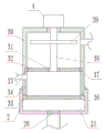
FIG. 2 is a cross-sectional view of a pretreatment apparatus;
fig. 3 is a sectional view of the adsorption and desorption apparatus;
FIG. 4 is a schematic view of the connection structure of the ring-shaped water spraying pipe and the conveying pipe.
Detailed Description
As shown in fig. 1-4, an activated carbon adsorption desorption catalytic combustion device comprises a pretreatment device 3, an adsorption desorption device 6, a combustion furnace 10, a heat recovery device 10a for recovering heat of the combustion furnace 10, and an exhaust tower 9, wherein the pretreatment device 3 comprises a first air inlet and a first air outlet, the adsorption desorption device 6 comprises a second air inlet, a second air outlet, a second desorption inlet, and a second desorption outlet, the combustion furnace 10 is provided with a third air inlet and a third air outlet, the heat recovery device 10a comprises a fourth air inlet and a fourth air outlet, the lower portion of the exhaust tower 9 is provided with a fifth air inlet, the top portion of the exhaust tower 9 is provided with a fifth air outlet, the fifth air outlet is communicated with the atmosphere, the first air outlet is communicated with the second air inlet through a first pipeline 5, the second air outlet is communicated with the fifth air inlet through a second pipeline 7, the second desorption inlet is communicated with the fourth air outlet through a first desorption pipeline 14, the second desorption outlet is communicated with the third air inlet through a second desorption pipeline 8, the fourth air inlet is connected with an air inlet pipe 13, a first fan 12 is installed on the air inlet pipe 13, a second fan 15 is installed on the first desorption pipeline 14, air valves are installed on the first pipeline 5, the first desorption pipeline 14, the second desorption pipeline 8 and the air inlet pipe 13, the pretreatment equipment 3 comprises a first shell 30, the bottom of the first shell 30 is detachably connected with a water receiving tank 2, the water receiving tank 2 is detachably connected with the first shell 30 through screws, a liquid outlet is formed in the water receiving tank 2 and is connected with a liquid discharge pipe 1, a first filtering device is arranged above the water receiving tank 2, a first air inlet is formed between the first filtering device and the water receiving tank 2, and a first air outlet is formed above the first filtering device; the first filtering device comprises a first filtering frame 33 and a supporting plate 31, the supporting plate 31 is arranged in the first filtering frame 33, a filtering net 2032 is arranged between the first filtering frame 33 and the supporting plate 31, the first filtering frame 33 is detachably and fixedly connected with the first shell 30, namely the first filtering device is detachably and fixedly connected with the first shell 30; a vertically arranged conveying pipe 38 is fixedly connected between the first filtering device and the top of the first shell 30, a pump 4 is fixed outside the first shell 30, the pump 4 is communicated with the conveying pipe 38, an annular water spray pipe 39 is sleeved outside the conveying pipe 38, the annular water spray pipe 39 is communicated with the conveying pipe 38 through a connecting pipe 39a, and a plurality of spray ports are respectively arranged on the annular water spray pipe 39 and the connecting pipe 39 a; a second filtering device is arranged between the water receiving tank 2 and the first filtering device, the second filtering device is detachably and fixedly connected with the first shell 30, and the second filtering device and the first filtering device are both detachably and fixedly connected with the first shell 30, so that the second filtering device and the first filtering device can be cleaned and replaced conveniently.
The heat recovery device 10a may adopt a conventional heat exchange device, and a hot air inlet may be provided in the heat recovery device 10a, and the hot air inlet is communicated with the third air outlet of the first combustion furnace 10 through a recovery pipe 11, so as to transfer hot air to the air in the heat recovery device 10a, thereby generating high-temperature gas.
The second filtering device includes a second filtering frame 35 adapted to the shape of the first casing 30, a filtering net 2032 is arranged in the second filtering frame 35, symmetrical second sliding blocks 36 are arranged on the top surface of the second filtering frame 35, a second sliding rail is arranged at the bottom of the first casing 30, and the second sliding blocks 36 are matched with the second sliding rail.
The water receiving tank 2 is sleeved at the bottom of the first shell 30 and is detachably and fixedly connected through a screw.
The first filter frame 33 is adapted to the first housing 30 in shape, the first symmetrical slide blocks 37 are disposed on the side surfaces of the first filter frame 33, the first slide rails 34 are disposed at the corresponding positions of the first housing 30, and the second slide blocks 36 are matched with the second slide rails.
In order to increase the firmness of the fixation of the first filter device and the second filter device, the first filter device and the second filter device can be further fixed by screws.
The bottom of the water receiving tank 2 is paved with activated carbon 21, the liquid discharge port is provided with a filter screen 20, the activated carbon 21 is prevented from falling off, the activated carbon 21 further filters the waste liquid, and the water quality of the discharged water is improved.
The adsorption and desorption equipment 6 comprises a second shell 63, and an upper adsorption device 61 and a lower adsorption device 62 are detachably connected in sequence from top to bottom in the second shell 63, so that the waste gas is fully absorbed.
The upper adsorption device 61 comprises an adsorption frame 64, the top and the bottom of the adsorption frame 64 can be detachably connected with fixed nets 65, an activated carbon layer 66 for adsorbing waste gas is arranged between the two fixed nets 65, one side of the second shell 63 is provided with a mounting opening, the shape of the mounting opening is matched with that of the adsorption frame 64, even if the adsorption frame 64 enters the second shell 63 from the mounting opening, symmetrical sliding grooves are arranged in the second shell 63 and are arranged on two sides of the mounting opening, and the adsorption frame 64 is in sliding connection with the sliding grooves; the lower adsorption device 62 has the same structure as the upper adsorption device 61.
A plurality of fixing pieces 60 are arranged outside the second shell 63, and the upper adsorption device 61 and the lower adsorption device 62 are respectively provided with a plurality of fixing pieces 60 correspondingly; one end of the fixing sheet 60 is hinged to the second casing 63 through a pin shaft, the fixing sheet 60 can rotate along the pin shaft, when the upper adsorption device 61 and the lower adsorption device 62 are installed, the outer end faces of the second filter frames 35 of the upper adsorption device 61 and the lower adsorption device 62 are flush with the outer wall of the second casing 63, the fixing sheet 60 is rotated, and the fixing sheet 60 is tightly pressed on the outer end faces of the second filter frames 35.
The number of the adsorption and desorption devices 6 is at least two, so that the adsorption and desorption devices 6 can be used alternately and subjected to desorption treatment.
The utility model discloses an impurity such as dust in the waste gas is got rid of to the shower water, and the water tank is connected to the water inlet of pump 4, can choose for use according to the concrete composition of waste gas to spray liquid, packs into in the water tank. When the device is used, waste gas enters the pretreatment equipment 3 through the first air inlet, the pump 4 is powered on to work, the pump 4 enables the water pump 4 to enter the conveying pipe 38 and then sequentially conveys the waste gas to the connecting pipe 39a and the annular water spraying pipe 39, the spraying liquid is sprayed out from the spraying port to wash impurities in the waste gas, the spraying liquid flows downwards, the impurities on the first filtering device are washed and fall onto the second filtering device, the waste liquid after filtering falls into the water receiving tank 2 and is discharged from the liquid discharging port, and the environment pollution is avoided. Waste gas overflows from the first air outlet of pretreatment device 3, then enters into absorption desorption equipment 6 along first pipeline 5, and waste gas adsorbs the filtration through lower adsorption device 62 and last adsorption device 61 in absorption desorption equipment 6, and the clean air after the filtration is along second pipeline 7, discharges from exhaust tower 9. The adsorption and desorption equipment 6 is subjected to desorption treatment periodically, an air valve on a first pipeline 5 of one adsorption and desorption equipment 6 is closed, the adsorption and desorption equipment 6 is subjected to desorption treatment, a first fan 12 and a second fan 15 work, a combustion furnace 10 works, the first fan 12 pumps air into heat recovery equipment 10a, hot gas in the combustion furnace 10 enters the heat recovery equipment 10a to enable the heat recovery equipment 10a to generate high-temperature gas, the air valves on the first desorption pipeline 14 and the second desorption pipeline 8 are opened, the hot gas enters the adsorption and desorption equipment 6 to evaporate waste gas in active carbon 21 to form high-concentration waste gas, the waste gas enters the combustion furnace 10 through the second desorption pipeline 8 to be combusted, and gas is introduced into the combustion furnace 10 in the early working period of the combustion furnace 10 and combusted to provide heat for the heat recovery equipment 10 a; and then, carrying out desorption treatment on other adsorption and desorption equipment 6 in sequence according to the steps, and continuing the work of the adsorption and desorption equipment 6 which finishes the desorption treatment. The first filtering device and the second filtering device are detached periodically for cleaning.
When the upper and lower suction devices 61 and 62 need to be replaced, the corresponding fixing piece 60 is rotated, and the upper and lower suction devices 61 and 62 are pulled to be replaced.
The above-mentioned embodiment is right the utility model discloses an explanation, it is not right the utility model discloses a limited, any right the scheme after the simple transform of the utility model all belongs to the protection scope of the utility model.
Claims (9)
1. An activated carbon adsorption desorption catalytic combustion device comprises a pretreatment device, an adsorption desorption device, a combustion furnace, a heat recovery device for recovering the heat of the combustion furnace and an exhaust tower, wherein the pretreatment device comprises a first air inlet and a first air outlet, the adsorption desorption device comprises a second air inlet, a second air outlet, a second desorption inlet and a second desorption outlet, a third air inlet and a third air outlet are arranged on the combustion furnace, the heat recovery device comprises a fourth air inlet and a fourth air outlet, a fifth air inlet is arranged at the lower part of the exhaust tower, a fifth air outlet is arranged at the top of the exhaust tower and communicated with the atmosphere, the first air outlet is communicated with the second air inlet through a first pipeline, the second air outlet is communicated with the fifth air inlet through a second pipeline, the second desorption inlet is communicated with the fourth air outlet through a first desorption pipeline, and the second desorption outlet is communicated with the third air inlet through a second desorption pipeline, fourth inlet port department is connected with the air-supply line, installs first fan on the air-supply line, installs the second fan on the first desorption pipeline, all installs the pneumatic valve, its characterized in that on first pipeline, first desorption pipeline, second desorption pipeline and the air-supply line: the pretreatment equipment comprises a first shell, the bottom of the first shell is detachably connected with a water receiving tank, a liquid outlet is formed in the water receiving tank, a first filtering device is arranged above the water receiving tank, a first air inlet is formed between the first filtering device and the water receiving tank, and a first air outlet is formed above the first filtering device; the first filtering device comprises a first filtering frame and a supporting plate, the supporting plate is arranged in the first filtering frame, a filtering net is arranged between the first filtering frame and the supporting plate, and the first filtering frame is detachably and fixedly connected with the first shell; a vertically arranged conveying pipe is fixedly connected between the first filtering device and the top of the first shell, a pump is fixed outside the first shell and is communicated with the conveying pipe, an annular water spraying pipe is sleeved outside the conveying pipe and is communicated with the conveying pipe through a connecting pipe, and a plurality of spraying ports are formed in the annular water spraying pipe and the connecting pipe; and a second filtering device is arranged between the water receiving tank and the first filtering device, and the second filtering device is detachably and fixedly connected with the first shell.
2. The activated carbon adsorption desorption catalytic combustion apparatus as set forth in claim 1, wherein: the second filtering device comprises a second filtering frame matched with the first shell in shape, a filtering screen is arranged in the second filtering frame, symmetrical second sliding blocks are arranged on the top surface of the second filtering frame, a second sliding rail is arranged at the bottom of the first shell, and the second sliding blocks are matched with the second sliding rail.
3. The activated carbon adsorption desorption catalytic combustion apparatus as set forth in claim 2, wherein: the water receiving groove is sleeved at the bottom of the first shell and is detachably and fixedly connected through a screw.
4. The activated carbon adsorption desorption catalytic combustion apparatus as set forth in claim 1, wherein: the first filter frame is matched with the first shell in shape, symmetrical first sliding blocks are arranged on the side face of the first filter frame, first sliding rails are arranged at corresponding positions of the first shell, and the second sliding blocks are matched with the second sliding rails.
5. The activated carbon adsorption desorption catalytic combustion apparatus as set forth in claim 1, wherein: the bottom of the water receiving tank is laid with active carbon, and the liquid discharge outlet is provided with a filter screen.
6. The activated carbon adsorption desorption catalytic combustion apparatus as set forth in claim 1, wherein: the adsorption and desorption equipment comprises a second shell, and an upper adsorption device and a lower adsorption device are detachably connected in sequence from top to bottom in the second shell.
7. The activated carbon adsorption desorption catalytic combustion apparatus as set forth in claim 1, wherein: the upper adsorption device comprises an adsorption frame, the top and the bottom of the adsorption frame can be detachably connected with fixed nets, an activated carbon layer for adsorbing waste gas is arranged between the two fixed nets, one side of the second shell is provided with an installation opening, the shape of the installation opening is matched with that of the adsorption frame, symmetrical sliding grooves are arranged in the second shell, the sliding grooves are arranged on two sides of the installation opening, and the adsorption frame is in sliding connection with the sliding grooves; the structure of the lower adsorption device is the same as that of the upper adsorption device.
8. The activated carbon adsorption desorption catalytic combustion apparatus as set forth in claim 7, wherein: a plurality of fixing pieces are arranged outside the second shell, and the upper adsorption device and the lower adsorption device are respectively provided with a plurality of corresponding fixing pieces; the one end of stationary blade is articulated through round pin axle and second casing, and the stationary blade can be followed the round pin axle and rotated, finishes when last adsorption equipment and lower adsorption equipment installation, goes up the outer terminal surface of adsorption equipment and lower adsorption equipment's second filter frame all with the outer wall parallel and level of second casing, rotates the stationary blade, and the stationary blade compresses tightly on the outer terminal surface of second filter frame.
9. The activated carbon adsorption desorption catalytic combustion apparatus as set forth in claim 1, wherein: the number of the adsorption and desorption devices is at least two.
Priority Applications (1)
| Application Number | Priority Date | Filing Date | Title |
|---|---|---|---|
| CN201922064758.2U CN211041019U (en) | 2019-11-26 | 2019-11-26 | Activated carbon adsorption desorption catalytic combustion equipment |
Applications Claiming Priority (1)
| Application Number | Priority Date | Filing Date | Title |
|---|---|---|---|
| CN201922064758.2U CN211041019U (en) | 2019-11-26 | 2019-11-26 | Activated carbon adsorption desorption catalytic combustion equipment |
Publications (1)
| Publication Number | Publication Date |
|---|---|
| CN211041019U true CN211041019U (en) | 2020-07-17 |
Family
ID=71539110
Family Applications (1)
| Application Number | Title | Priority Date | Filing Date |
|---|---|---|---|
| CN201922064758.2U Active CN211041019U (en) | 2019-11-26 | 2019-11-26 | Activated carbon adsorption desorption catalytic combustion equipment |
Country Status (1)
| Country | Link |
|---|---|
| CN (1) | CN211041019U (en) |
Cited By (2)
| Publication number | Priority date | Publication date | Assignee | Title |
|---|---|---|---|---|
| CN113154902A (en) * | 2021-04-26 | 2021-07-23 | 惠瑞净化科技(江苏)有限公司 | Method for recycling waste gas heat of lithium battery clean room |
| CN113713585A (en) * | 2021-09-15 | 2021-11-30 | 安徽紫朔环境工程技术有限公司 | Flue gas desulfurization and denitrification device and desulfurization and denitrification method thereof |
-
2019
- 2019-11-26 CN CN201922064758.2U patent/CN211041019U/en active Active
Cited By (3)
| Publication number | Priority date | Publication date | Assignee | Title |
|---|---|---|---|---|
| CN113154902A (en) * | 2021-04-26 | 2021-07-23 | 惠瑞净化科技(江苏)有限公司 | Method for recycling waste gas heat of lithium battery clean room |
| CN113713585A (en) * | 2021-09-15 | 2021-11-30 | 安徽紫朔环境工程技术有限公司 | Flue gas desulfurization and denitrification device and desulfurization and denitrification method thereof |
| CN113713585B (en) * | 2021-09-15 | 2023-10-24 | 安徽紫朔环境工程技术有限公司 | Flue gas desulfurization and denitrification device and desulfurization and denitrification method thereof |
Similar Documents
| Publication | Publication Date | Title |
|---|---|---|
| CN202105575U (en) | Wet type waste gas comprehensive control apparatus | |
| CN201108793Y (en) | Purifying means for unwanted exhaust gas advanced treatment | |
| WO2017152340A1 (en) | Pharmaceutical and chemical industry emission purification equipment | |
| CN211041019U (en) | Activated carbon adsorption desorption catalytic combustion equipment | |
| CN210495677U (en) | A air environmental protection filter equipment for waste gas high-efficient handling | |
| CN109985480A (en) | Exhaust treatment system | |
| CN204447751U (en) | A kind of labyrinth type biological purification plant | |
| CN214416003U (en) | Organic waste gas treatment device | |
| CN206295754U (en) | A kind of activated carbon catalytic converter | |
| CN113101768A (en) | Waste gas treatment device | |
| CN205461588U (en) | Papermaking waste gas treatment system | |
| CN219462966U (en) | Organic waste gas purification online cleaning type zeolite adsorption and desorption runner device | |
| CN210495616U (en) | Detachable desorption catalytic combustion organic waste gas treatment device | |
| CN205109291U (en) | Organic gas's processing apparatus | |
| CN206996278U (en) | A kind of photooxidation catalytic waste gas cleaning equipment | |
| CN206414944U (en) | A kind of plasma cleaning mechanism of high-temp waste gas | |
| CN203648322U (en) | Kiln fume exhausting device | |
| CN211358243U (en) | Workshop exhaust gas purification device | |
| CN207532987U (en) | A kind of exhaust treatment system | |
| CN205461645U (en) | Special high -efficient desorption system of adsorbing of spraying waste gas | |
| CN206577579U (en) | A kind of greasy filth waste gas purification and residual heat using device | |
| CN215372541U (en) | Waste gas waste heat recovery device for boiler | |
| CN218721607U (en) | Environment-friendly energy-saving emission-reducing smoke abatement device | |
| CN213375703U (en) | Flue gas dust removal equipment | |
| CN220061806U (en) | Be used for boiler tail gas purification dust collecting equipment |
Legal Events
| Date | Code | Title | Description |
|---|---|---|---|
| GR01 | Patent grant | ||
| GR01 | Patent grant |